FREE SHIPPING FOR ALL DOMESTIC ORDERS OVER $75 - NO SALES TAX OUTSIDE OF NJ!

Learn how to install our DIY Heatsink in your Canon EOS R5! If you would prefer us to convert it for you risk-free, head over to our Canon R5 Heatsink Overheating Mod Service!

When the Canon EOS R5 was released, we learned that it overheats quickly

in 8K shooting and in some 4K modes. Initially, this was handled through a timer chip in the camera independent of the actual temperature.  After public backlash, Canon quickly released a new firmware that patched the timer issue and started actually using the camera temperature data instead, but even with this upgrade the performance boost was minor.

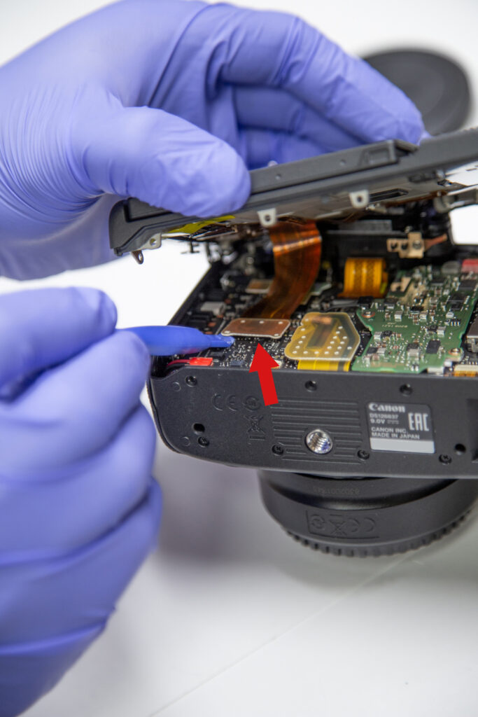
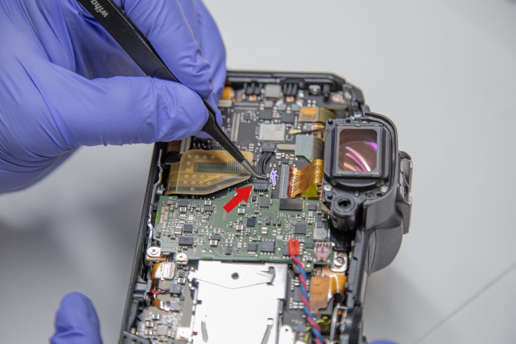
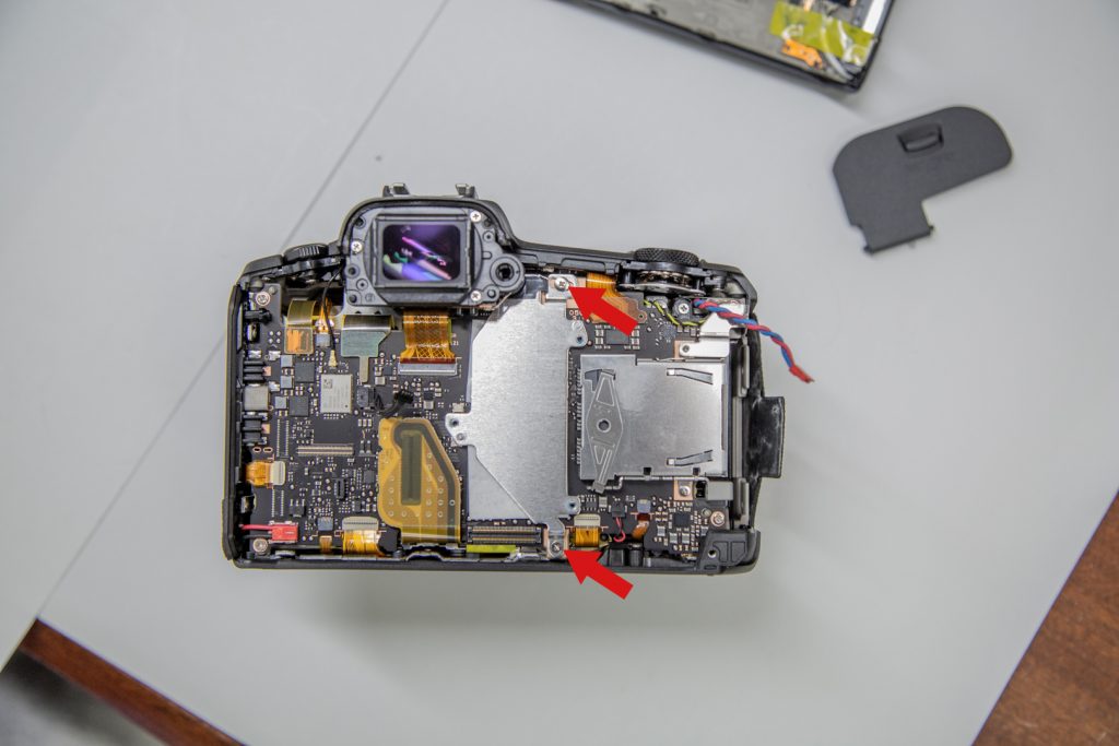
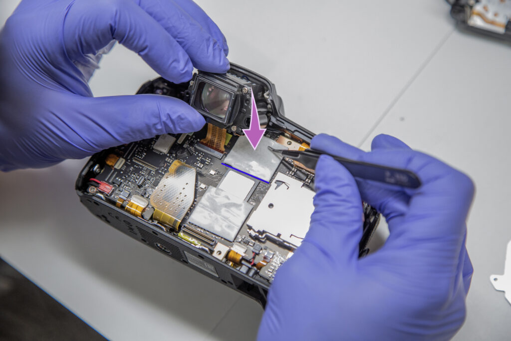
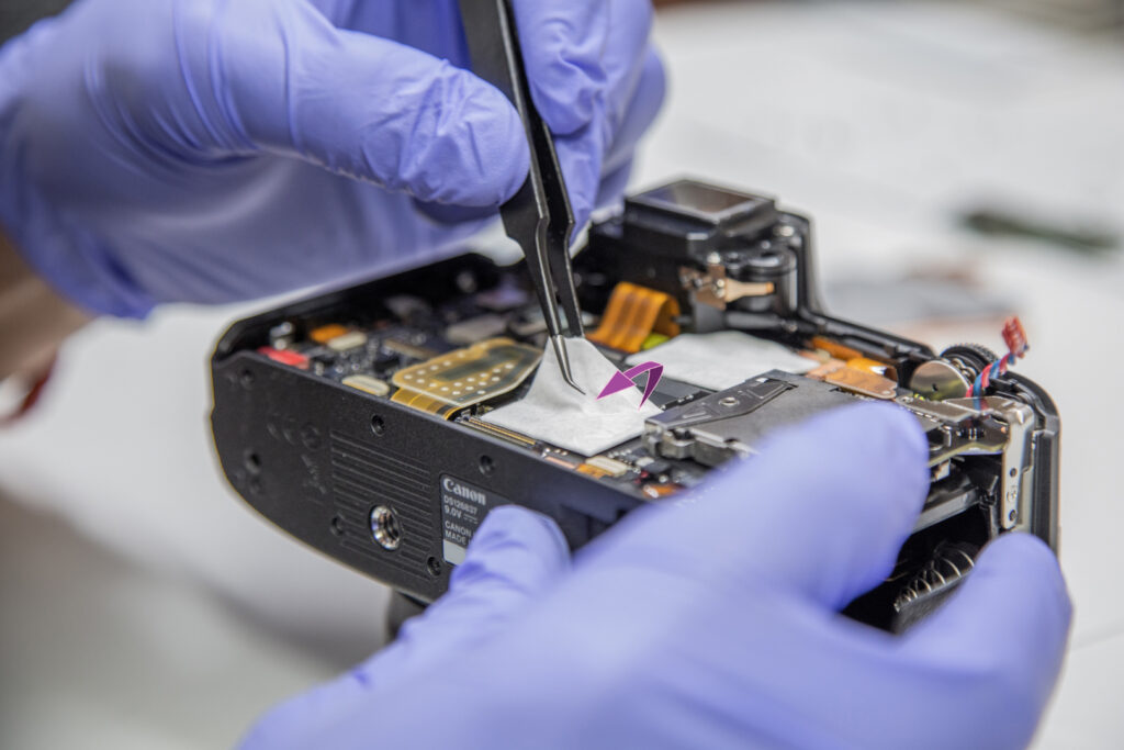
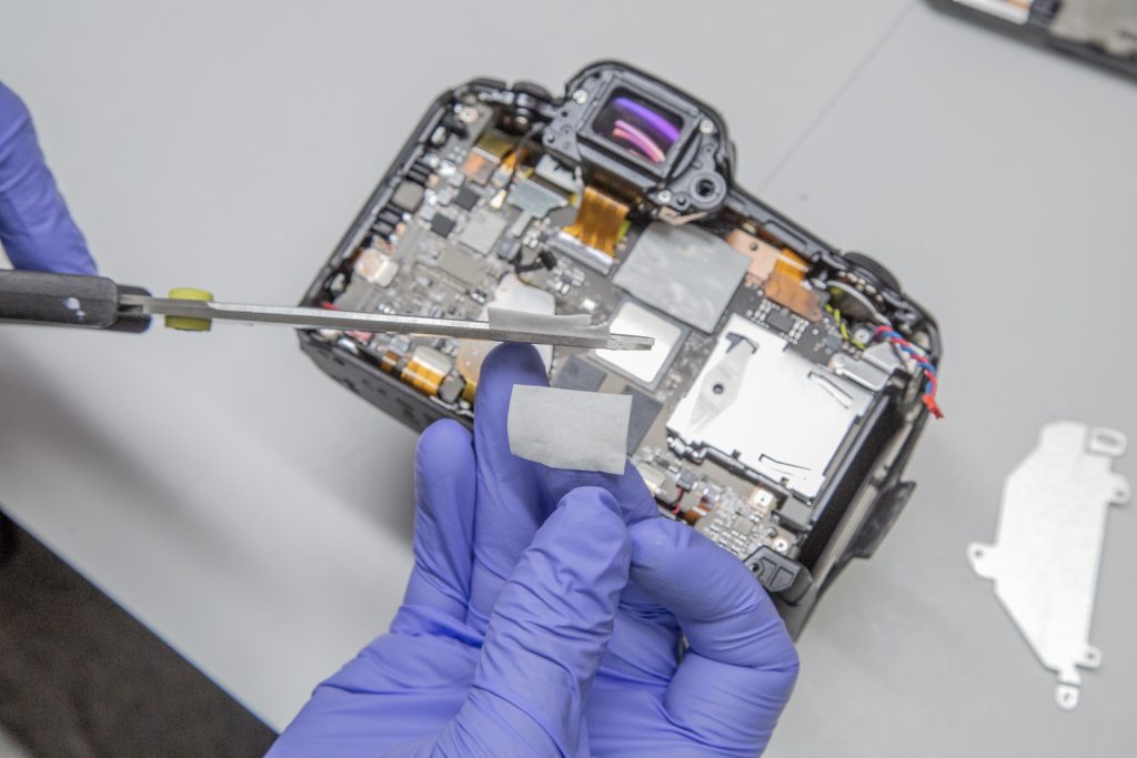
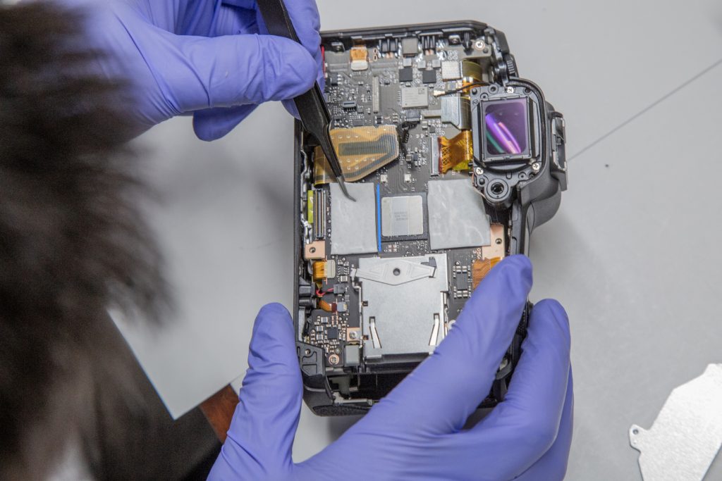
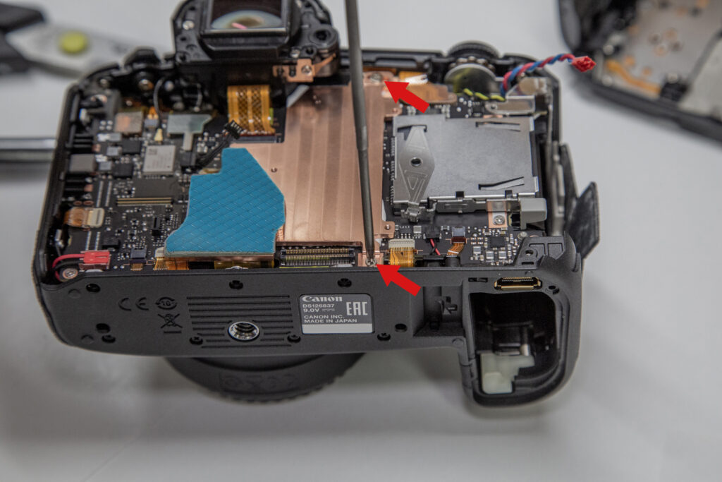
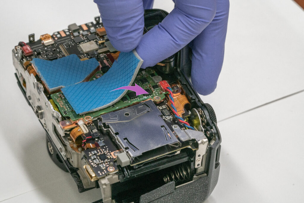
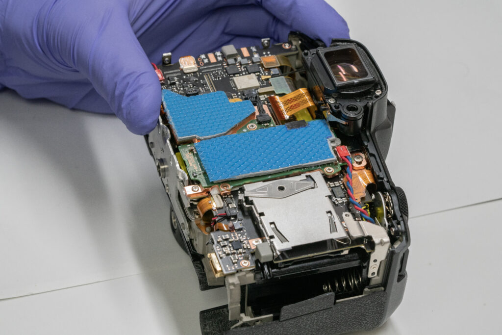
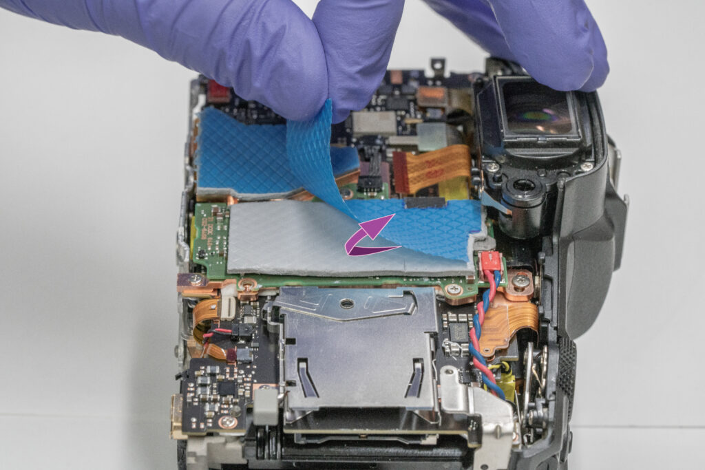
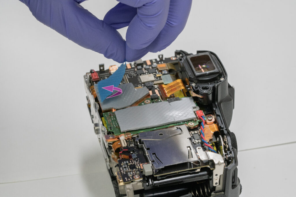
In several thermal analyses of the camera, the processor on the motherboard seemed to generate most of the heat. In the stock design, Canon places two thermal pads partially over the processor and pumps the heat into a small heatsink. That heatsink however sits under another board and does not vent heat anywhere further.

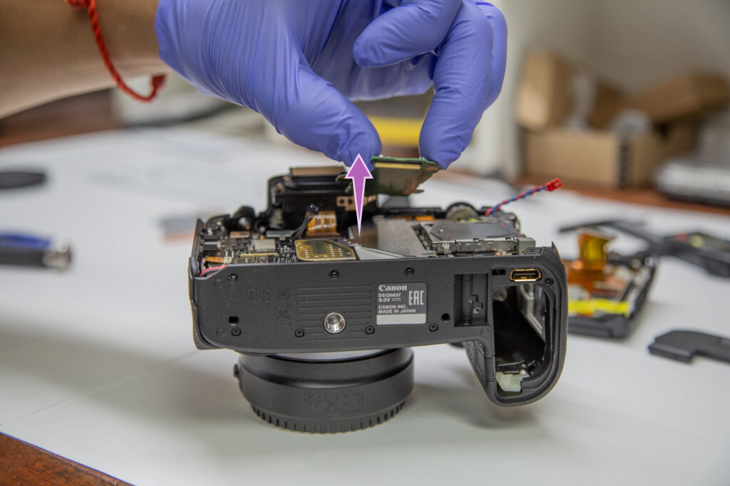
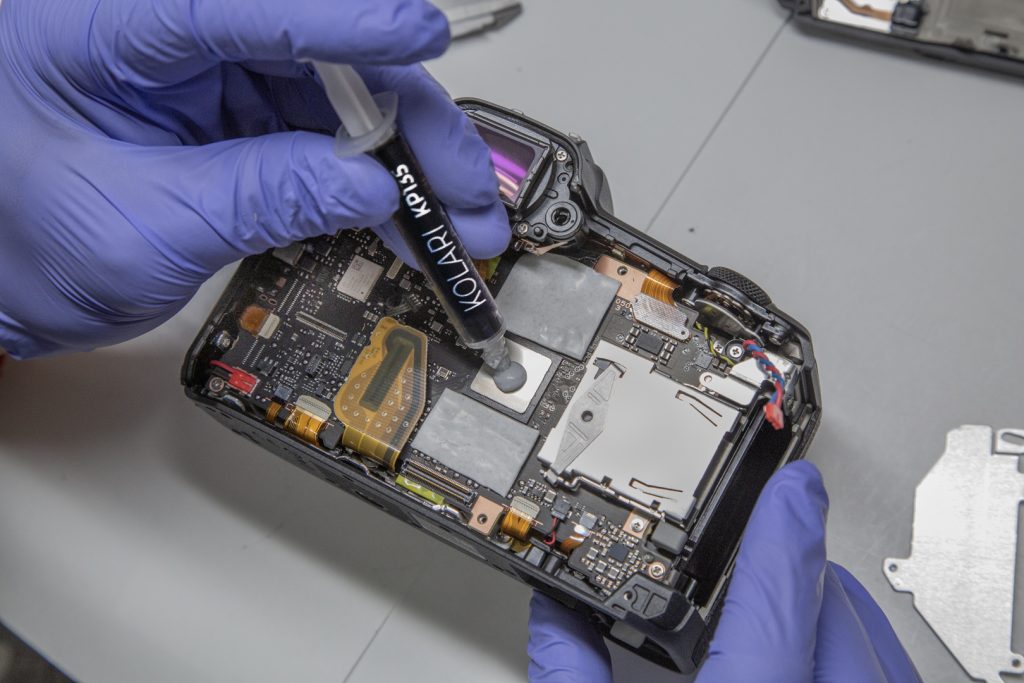
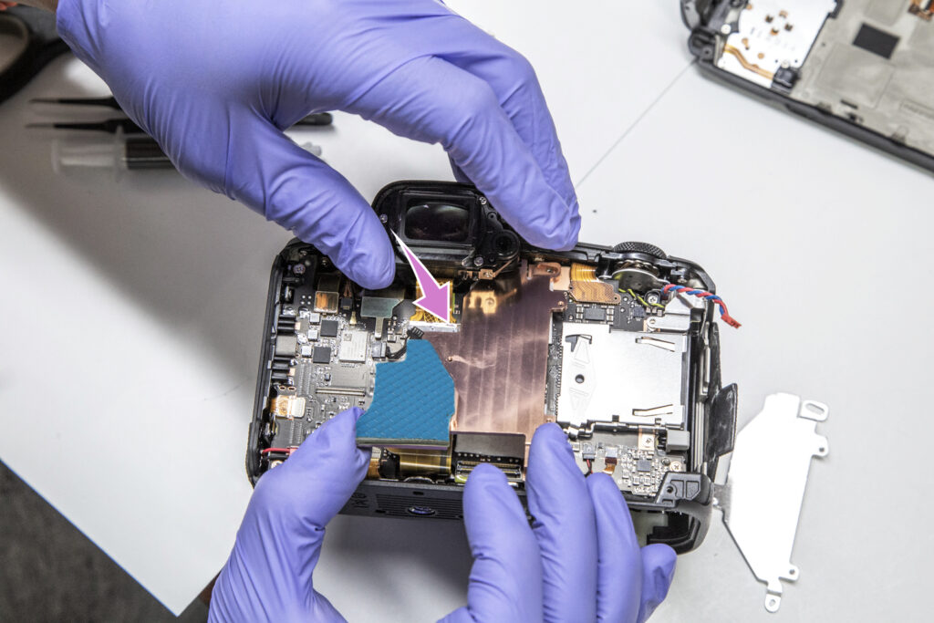
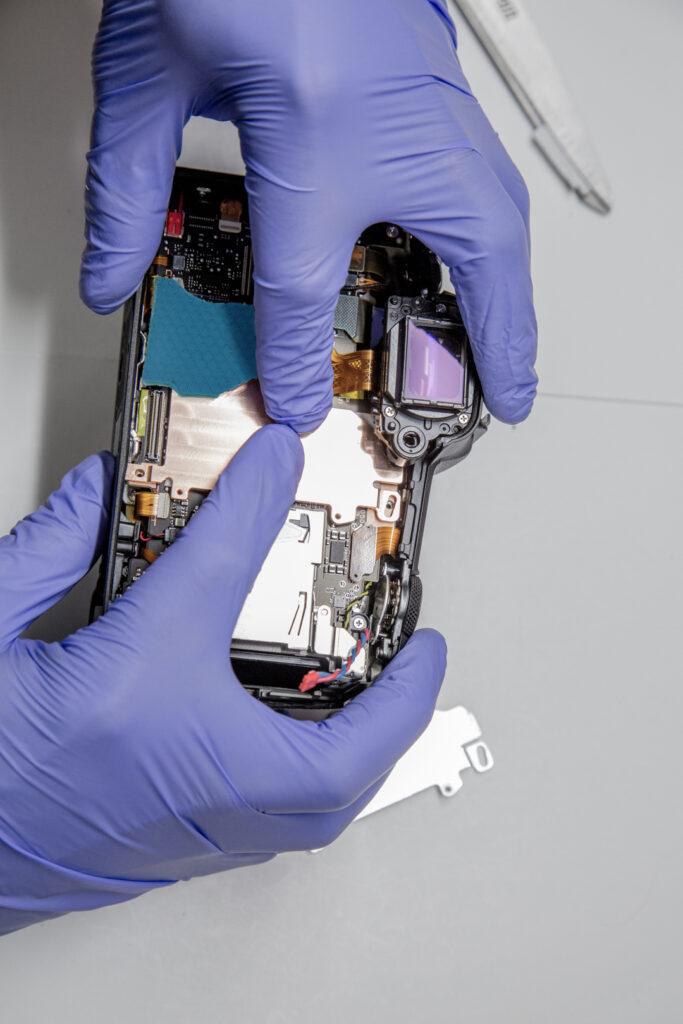
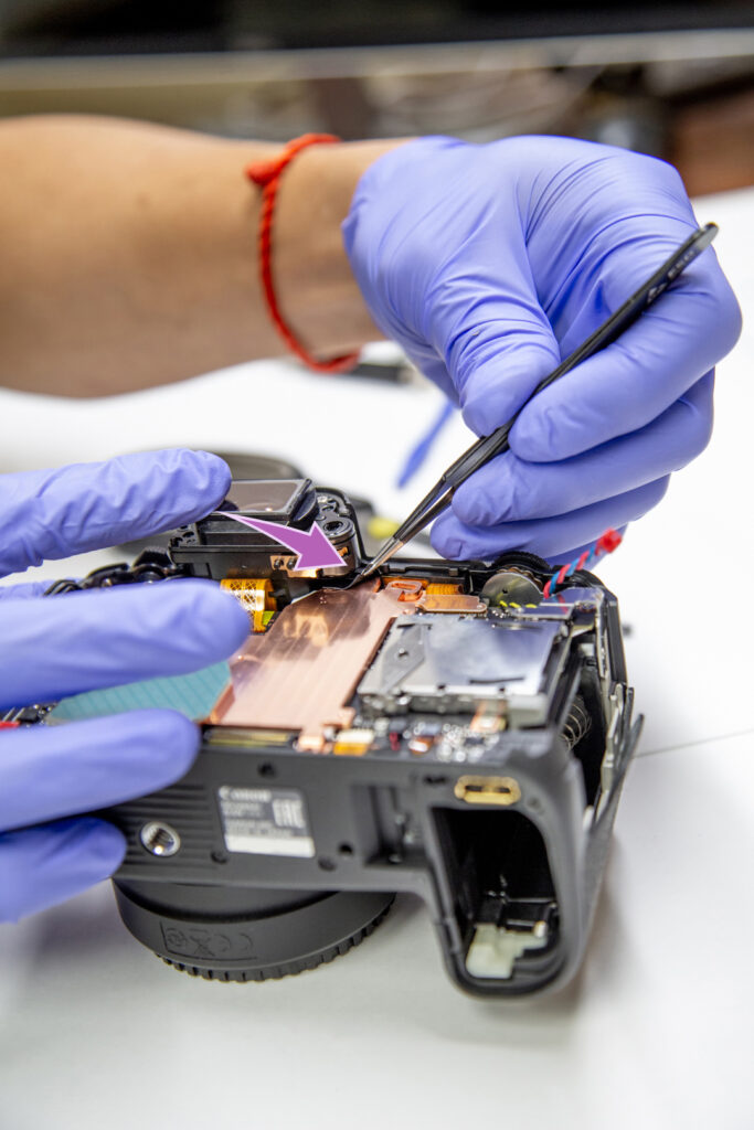
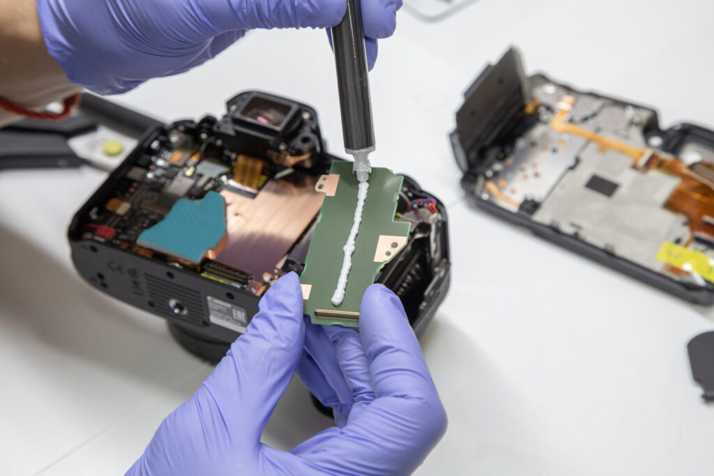
To remedy this problem, we took an R5 apart and designed a new heatsink to vent the heat from the processor to the camera case where it could dissipate faster. We tested aluminum initially, but eventually settled on a thick copper heatsink to transfer heat more efficiently. This design draws heat out of the processor and brings it around the motherboard and out to the rear case where it transfers heat through a custom high-efficiency thermal pad.

Disclaimer: Opening your camera will void the manufacturer’s warranty. This procedure will expose your camera to the risk of static shock and may leave your camera non-operational. Cameras contain high voltages even when turned off, by attempting this conversion you can get hurt or killed from the high voltage present – you do so at your own risk. We are not responsible for any damage to your camera, any harm you may suffer, or any consequential or special damages.

Required tools:


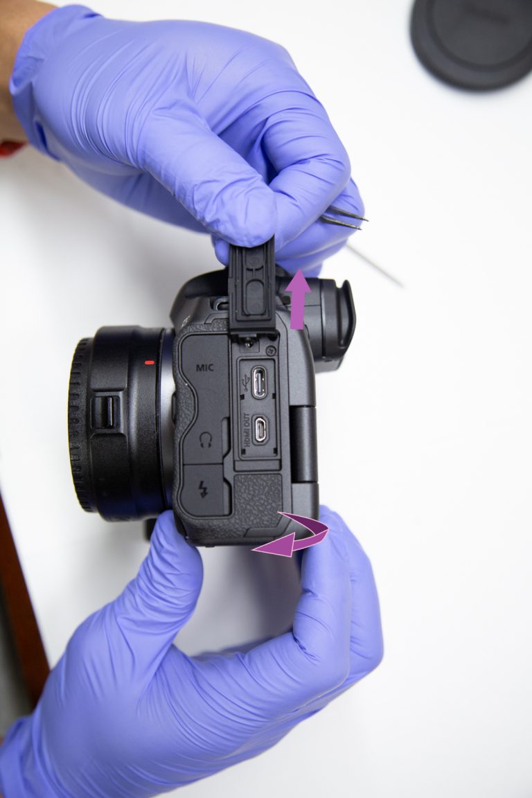
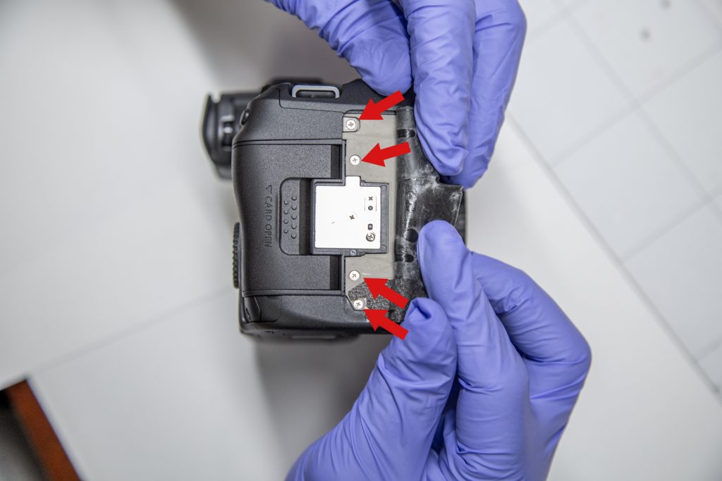
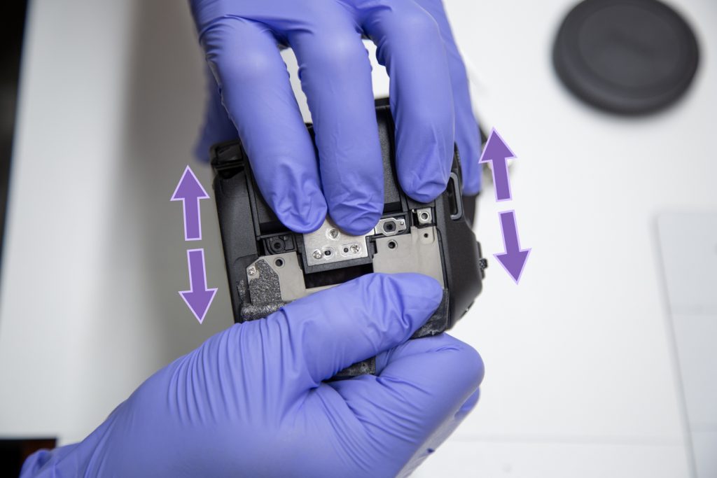
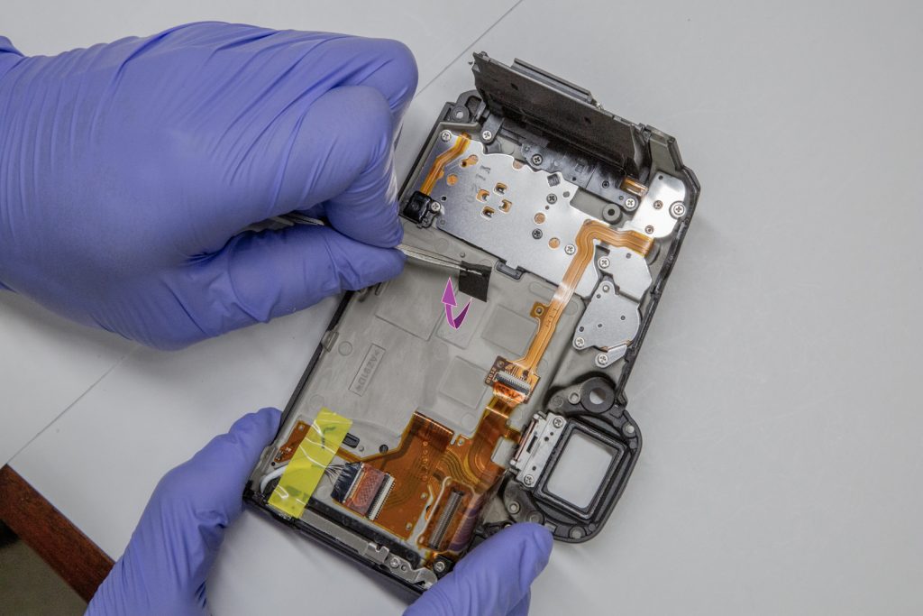
For the sake of clarity, left and right will be from the perspective of facing the back of the camera.

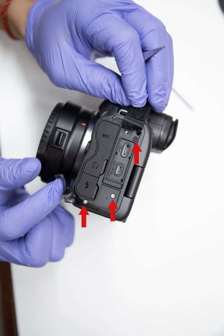
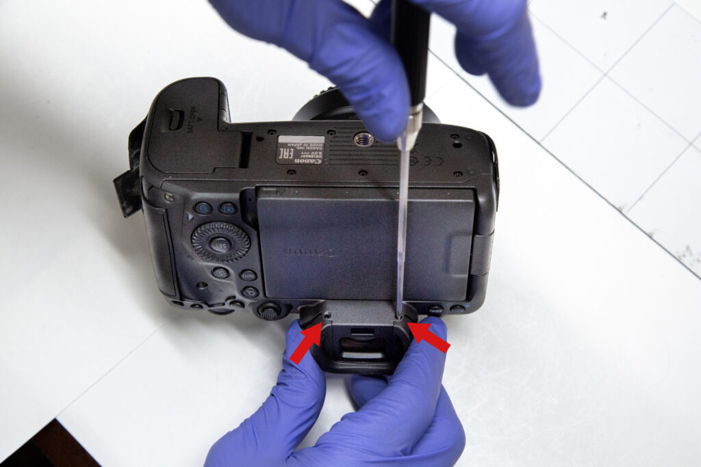
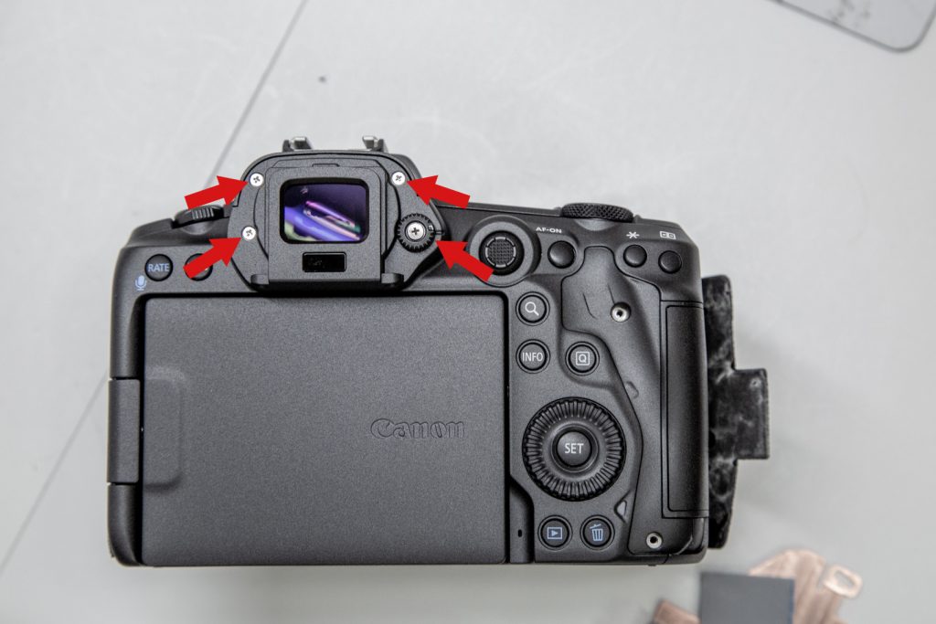
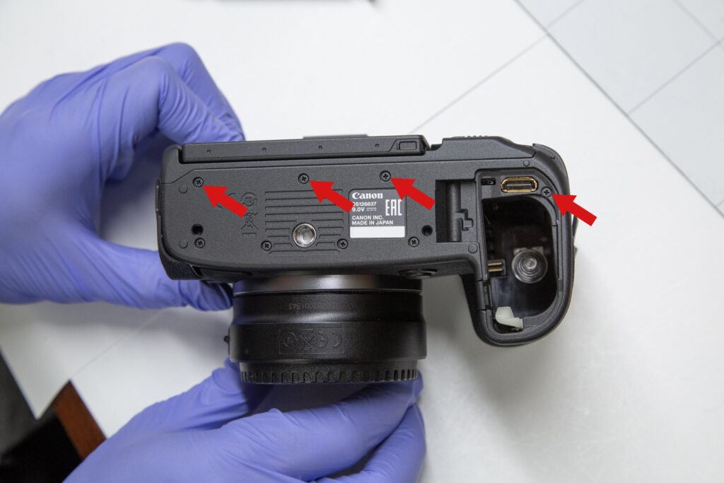
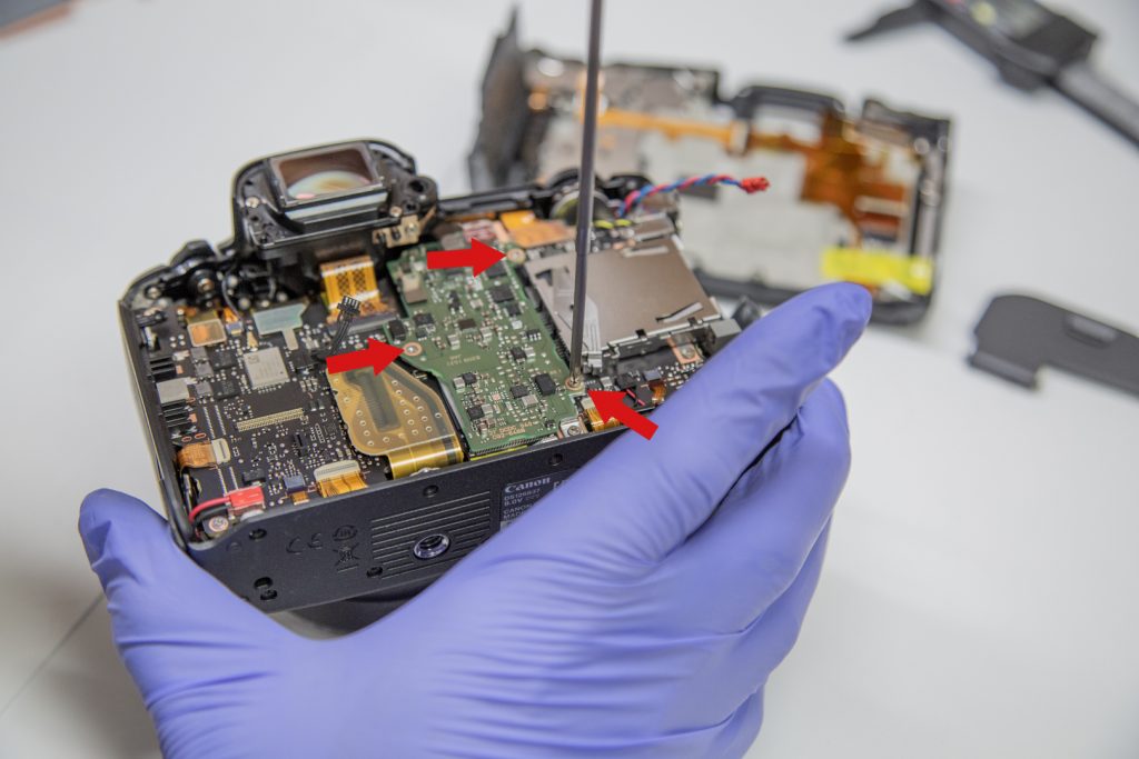
We recommend keeping all screws separated by section for each step and marking them. For example, ‘bottom side’, ‘left side’, ‘circuit board’, ‘viewfinder exterior’, ‘viewfinder interior’, etc.

We also advise arranging the screws in the same position they were in, in the camera, relative to each other. Screws coming from the same section can be different. 

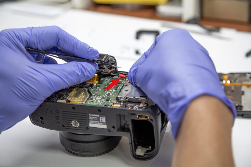
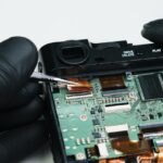
Be sure to remove the battery, lens and memory card before starting. This is also a good time to put on your anti-static wrist strap.


3U7A2414 2

Lift up the cover of the USB-C/HDMI ports on the left side. Use the tweezers to carefully peel back the leathers. Start at the corner, by inserting the point of the tweezers into and under the seam. alternate between pulling it back and pushing the blunt edge of the tweezers to wedge between them. Pull it back until the 2 screws are uncovered.

3U7A2419 3

Remove the 3 screws marked in the photo. 

3U7A2423 5 copy

On the rear-side, pull back the leathers like in the previous step, revealing 2 screws on the top and bottom right-hand side. 

3U7A2431 8

Remove the screws as indicated. 

3U7A2444 11

On the right-side of the camera, peel back the leathers starting with the tab near the SD card slot. Pull it back until you see a row of screws. Remove the top 2 and bottom 2 screws in the matte grey part, as indicated in the photo. (You do not need to remove the 3
middle screw in the metal section)

3U7A2458 15 copy

Flip the camera over and remove the 2 screws on the underside of the viewfinder, and then you’ll be able to pull off the eyepiece, revealing 4 screws.

3U7A2459 16

Remove the 4 screws as indicated. Be careful when removing the diopter dial (focusing dial), as it is composed of multiple parts which may separate.

3U7A2479 17 copy

Turn the camera upside down and open or remove the battery door. Remove the 4 screws as marked. (You do not need to remove the other screws)

3U7A2485 20

Start pulling the back panel separate from the rest of the camera, but do not completely pull it off yet. To separate, gently tug each side one at a time, along the seam.

3U7A2490 21 copy
3U7A2502 23 copy
3U7A2512 24 copy

Once the back panel is disconnected, place the camera on its face and lift the back panel slightly off the camera. Underneath the back panel, you’ll see a ribbon still connecting it to the camera’s motherboard. Using tweezers or a flathead screwdriver, carefully pry the plastic ribbon connection off, disconnecting it from the motherboard. (Be careful not to scratch or damage the board) Place the back panel to the side.

3U7A2534 27 copy

On the top right corner of the board, there is a pair of twisted red and blue wires going to a red connector attached to the motherboard. Using the tweezers, lift the red connector upwards to unclip it.

3U7A2538 28

Using the tweezers, pull back the black wire-ribbon connection from the circuit board.

3U7A2552 30

Unscrew the 3 screws indicated, on the top-right, left-middle, and bottom-right of the circuit board.

3U7A2563 32 copy

Remove the circuit board.

3U7A2568 33

Unscrew the 2 screws holding the OEM heatsink.

3U7A2573 35 copy

Beneath the viewfinder there is a black heat absorption film. Use the tweezers to peel it back, off of the metal heatsink and remove the OEM heatsink.

3U7A2580 37 copy
3U7A2587 38 copy

Peel off the upper thermal pad and move it back to the edge of the processor.

3U7A2596 40 copy
3U7A2603 42 copy

Peel off the lower thermal pad and cut off approx. ¼inches (7mm). Place it at the lower edge of the processor.

3U7A2622 45
3U7A2625 46
3U7A2630 47

Take Kolari thermal paste and put a pea-sized drop on the processor.

3U7A2641 50 copy

Take the Kolari copper replacement heat-sink included in your kit and line it up in place of the old one.

3U7A2657 53 copy

Gently press it down

3U7A2660 54 copy 2

Set the black heat-absorption film back into place over the copper.

3U7A2675 57 copy 2

Screw in the copper heatsink plate as indicated, using the screws from the OEM plate.

3U7A2690 59 copy 2

On the underside of the circuit board, pour a thin line of Kolari thermal paste along the center.

3U7A2692 60 copy 2
3U7A2697 61 copy

Press the circuit board back into place and screw it in.

DSC099w24
DSC09930 1

Take the rectangular heat-pad from your kit, peel off the clear plastic film and lay it over the circuit board. Place it so that the L-shaped cut out is in top-right corner.

DSC09939 copy
DSC09948 copy

Peel off the blue plastic.

3U7A2731 67

On the back panel of the camera, remove the black heat absorption film in the center.

  Close the camera by repeating the previous steps in reverse order. Do not over-tighten the screws on the underside of the
camera. 


Disclaimer: Opening your camera will void the manufacturer’s warranty. This procedure will expose your camera to the risk of static shock and may leave your camera non-operational. Cameras contain high voltages even when turned off, by attempting this conversion you can get hurt or killed from the high voltage present â€“ you do so at your own risk. We are not responsible for any damage to your camera, any harm you may suffer, or any consequential or special damages.


PLEASE NOTE:

While we have seen these improvements with most camera setups, we have noticed that this modification’s performance can be negatively impacted by certain external devices and CF Express memory cards. Our tests were conducted and our results recorded using Sony Tough CF Express cards, unfortunately, we have found that ProGrade CF Express cards can cause greatly decreased heat dissipation performance. We have not tested other cards yet but be cautious if using card brands other than Sony. Additionally, while we have tested a number of camera setups we have found some variation in the performance based on the use of certain external devices and other parameters.

Skip to content