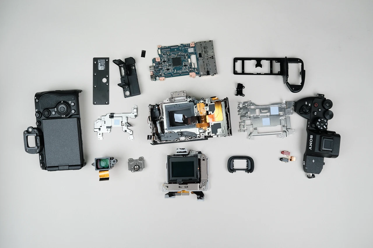
Fujifilm GFX100RF Teardown and Disassembly
Written by Phillip Andrew Iglesias
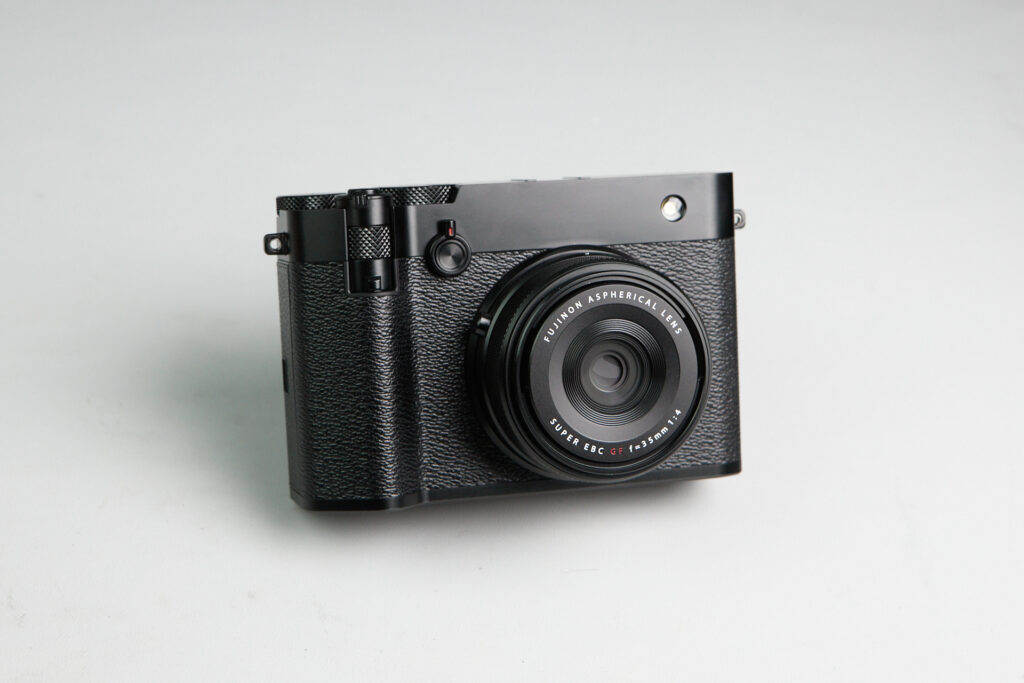
The Fujifilm GFX100RF was a surprising release coming from Fujifilm released on March 2025. The camera itself differs from the typical GFX line being that it draws heavy design inspiration from their XE-series of cameras.
The Fujifilm GFX100RF is a fixed lens medium format rangefinder mirrorless camera, so it doesn’t have a bayonet mount for swapping lenses. With that in mind, this camera is not compatible with our Magnetic Clip-in Filters for Fujifilm GFX-mount cameras. However, it can still be converted to full-spectrum through our medium format conversion service!
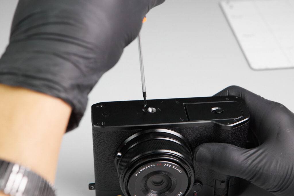
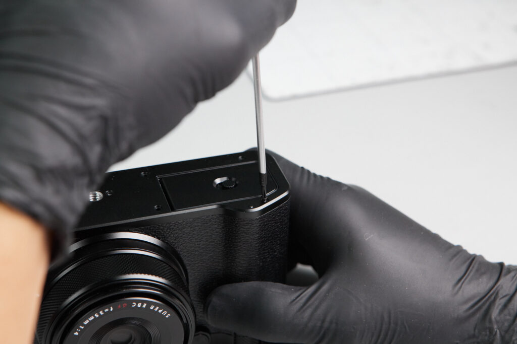
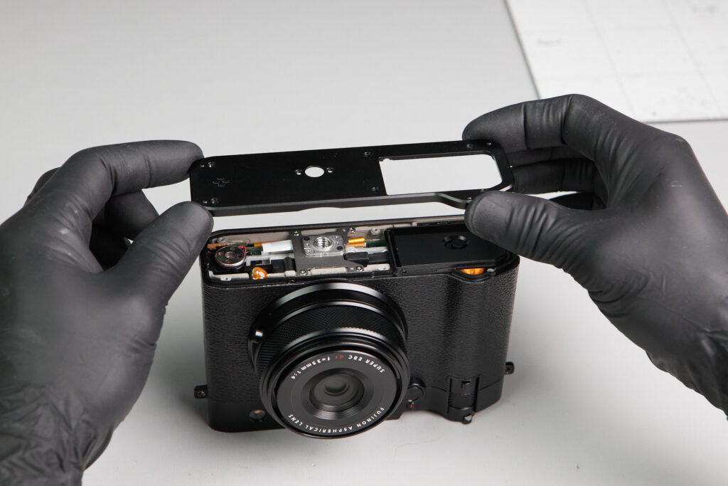
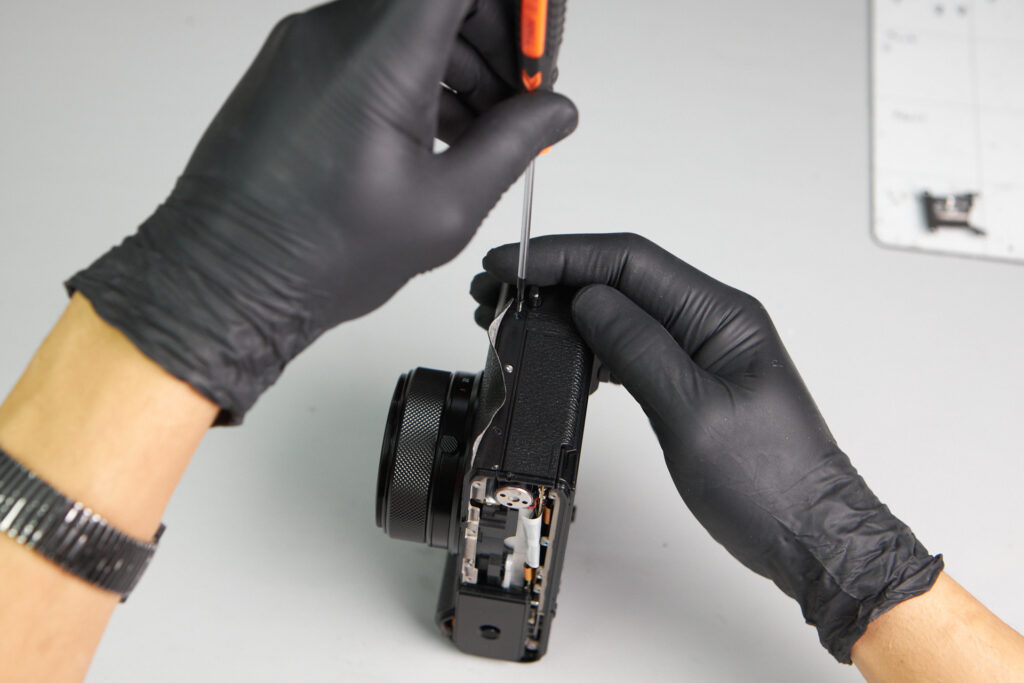
We started with removing the baseplate of the camera. In total, there were eight screws to remove to detach the baseplate. No surprises here.
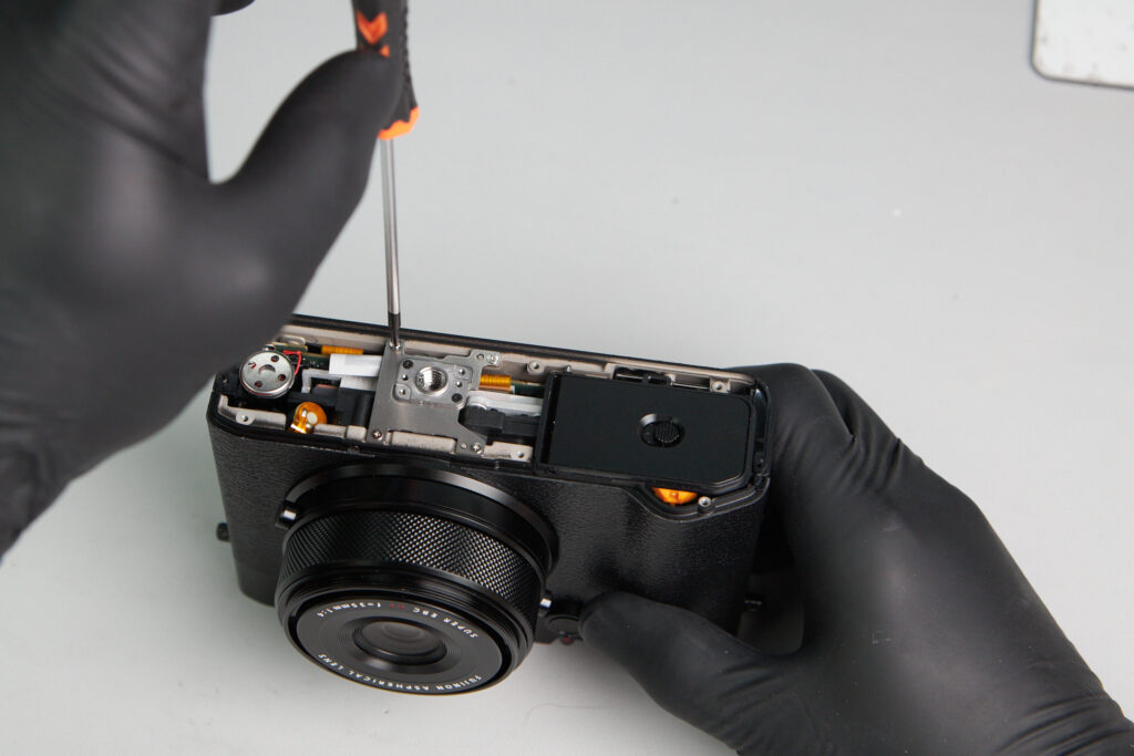
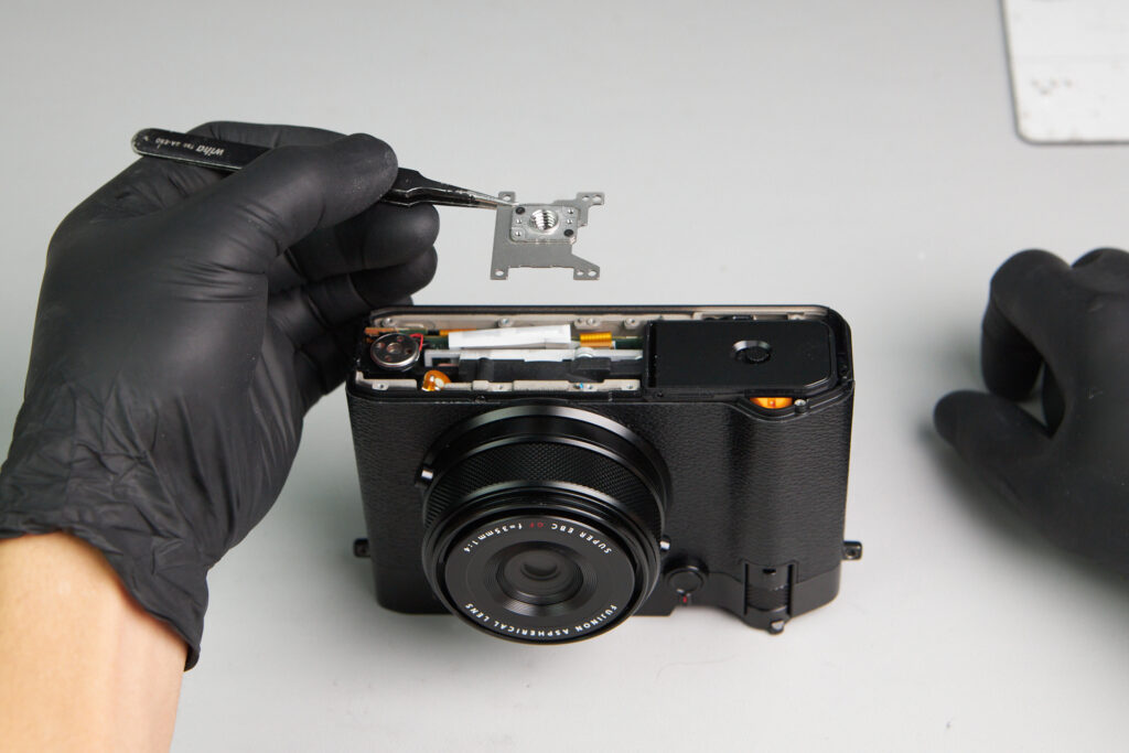
The tripod mount was out in the open, so it was an easy part to remove. Four screws held it down.
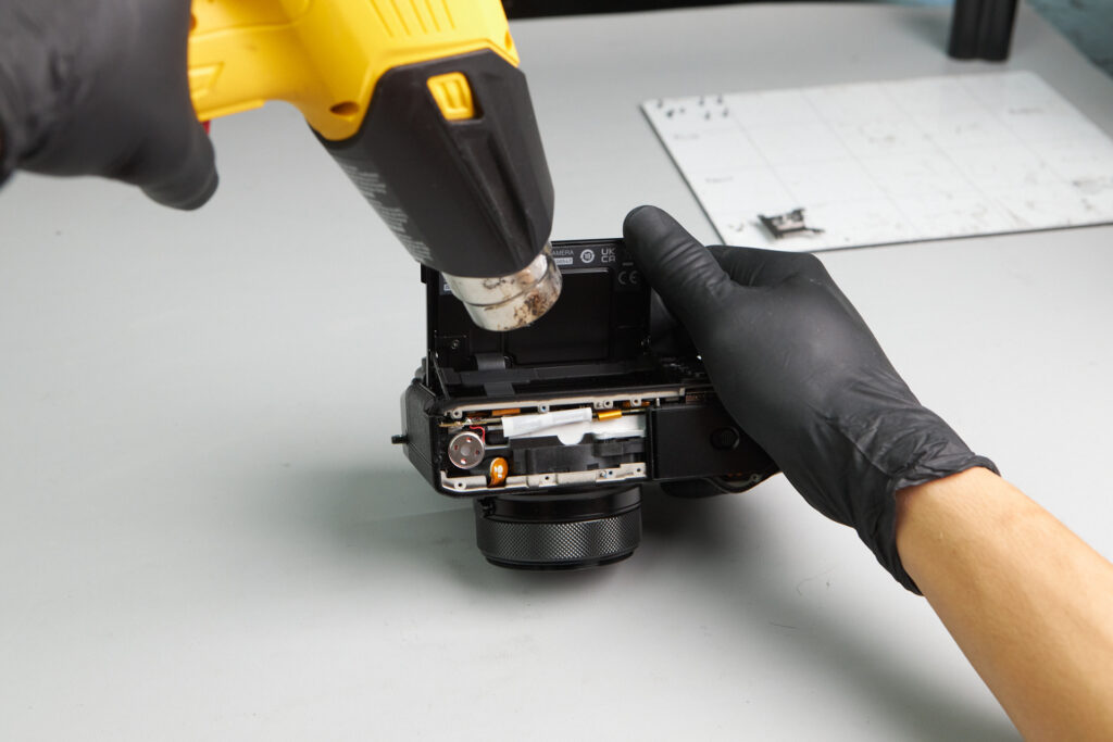
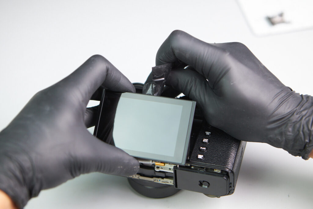
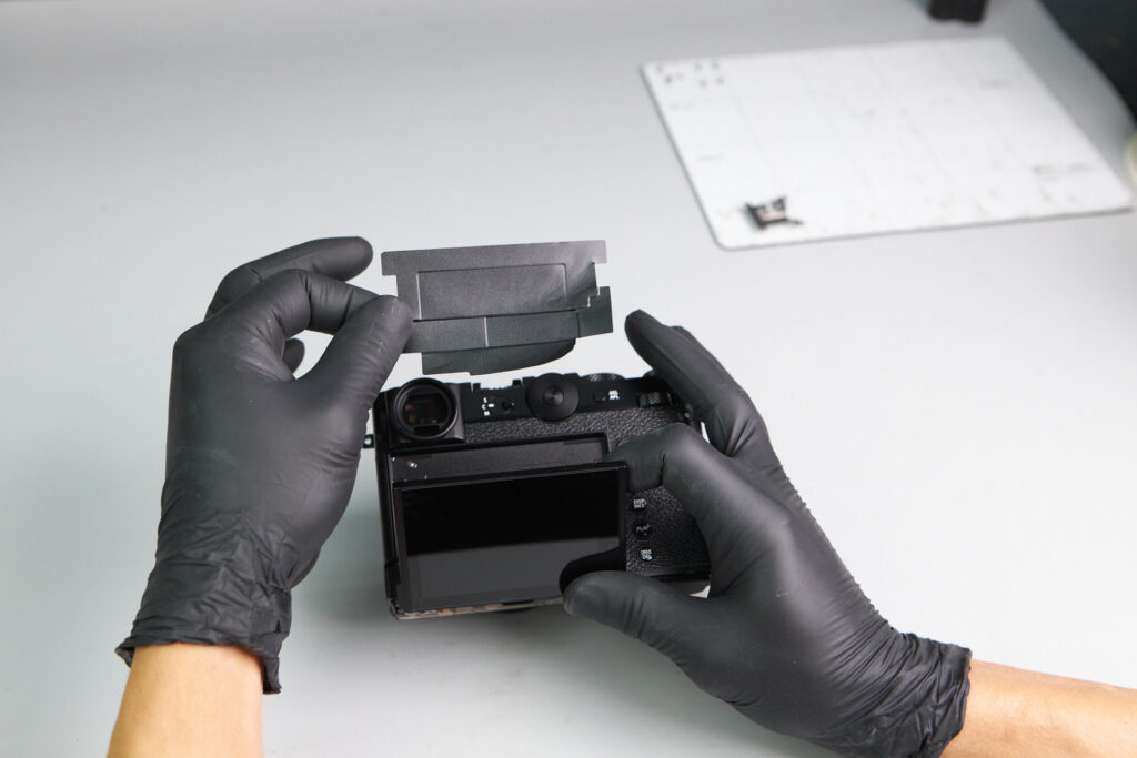
Screws are commonly found behind the LCD screen; sometimes they will be located underneath the back sticker cover. Typically, we’re able to carefully peel it off to expose screws, but in the case with the GFX100RF, it was so tightly grafted to the camera that we needed assistance from a heat gun. The warm air from the heat gun softens the adhesive and makes it easier to peel.
Of course, we needed to use a light hand and be extra careful in using the heat gun, since prolong use of it on the camera could potentially damage or warp parts of it.
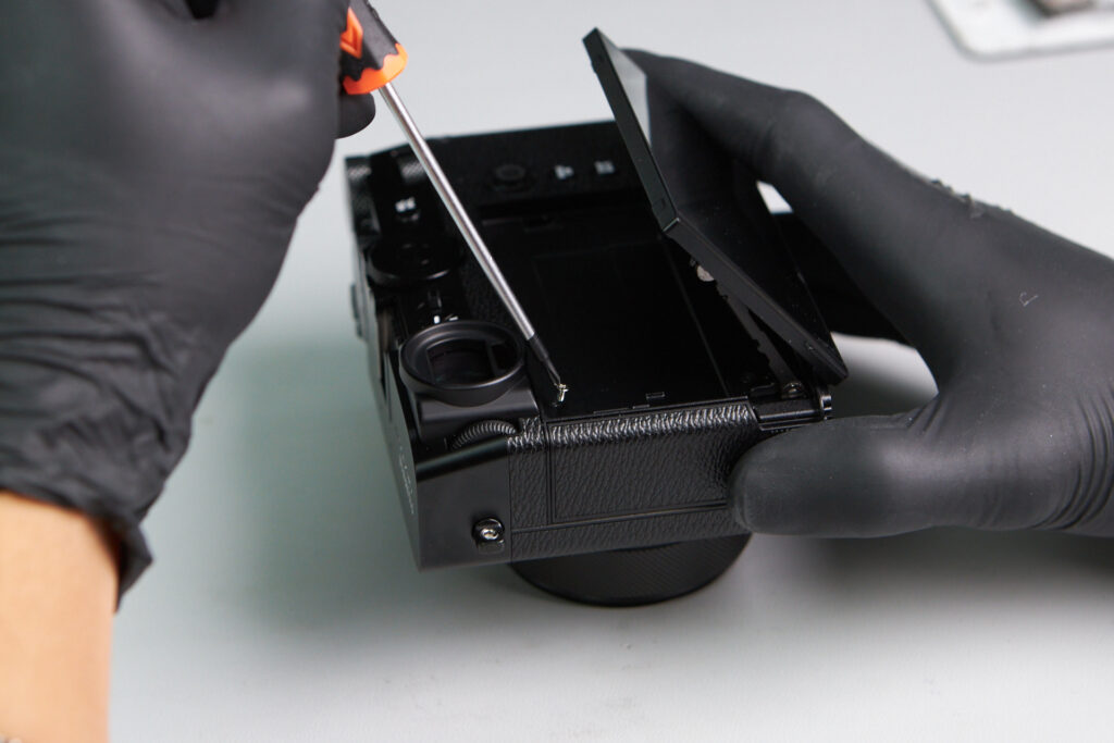
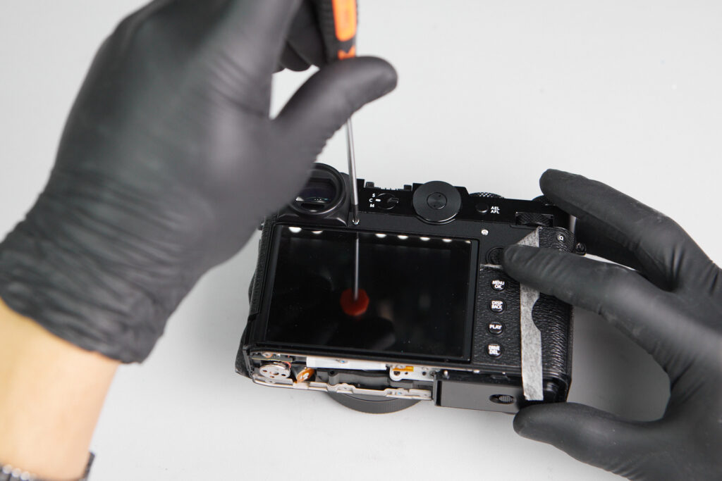
After a careful and tedious process of removing the back adhesive, we found one tiny screw in the upper corner.
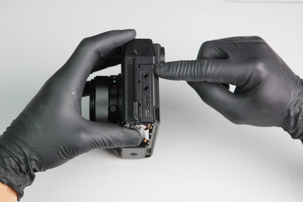
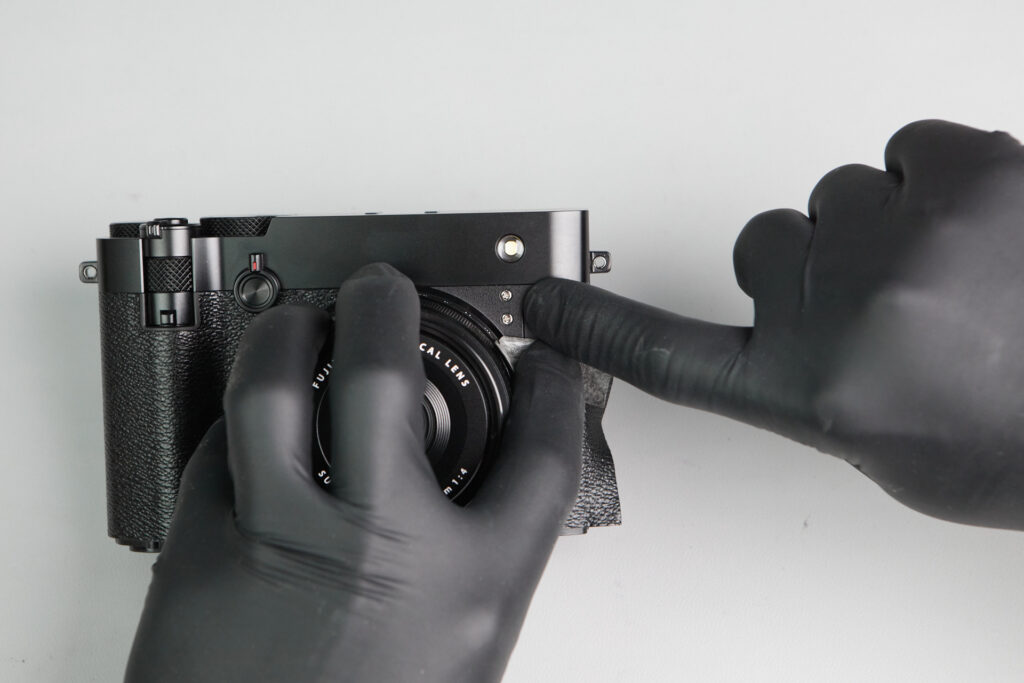
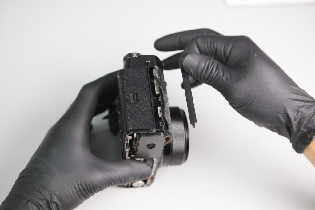
Interestingly, there were no screws underneath the port side cover of the camera, which is common for many cameras we’ve seen. There were screws located underneath the leather covering, counting four altogether.
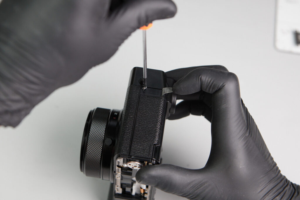
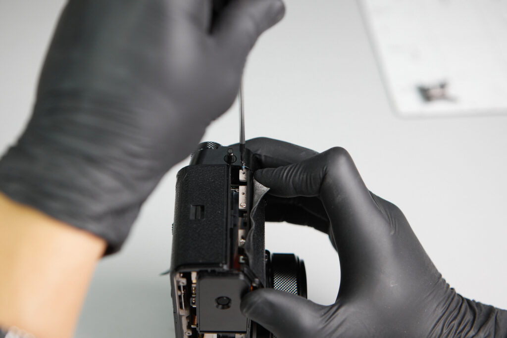
There are two screws below the left side of the faux leather covering. We also noticed a separate cover here, but since it’s a cover, it was irrelevant to remove it since it doesn’t relate to the entire camera body chassis.
Two screws were found underneath the leather on backside of camera.
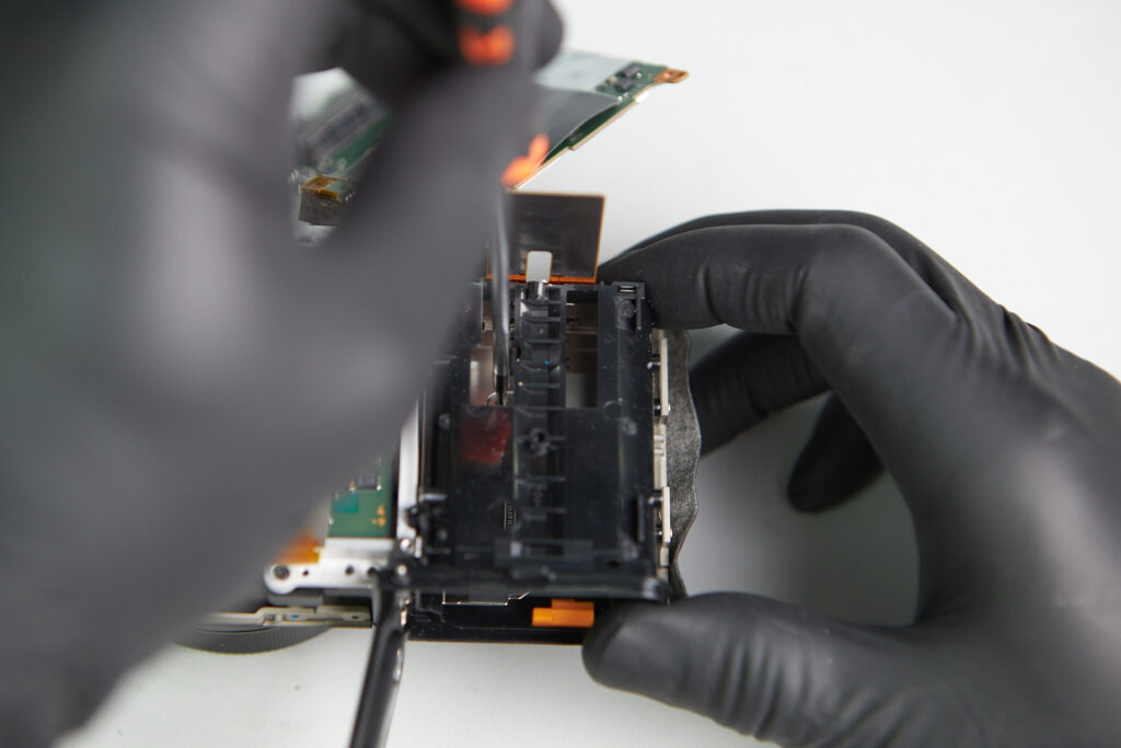
There are three screws underneath the SD card slot cover.
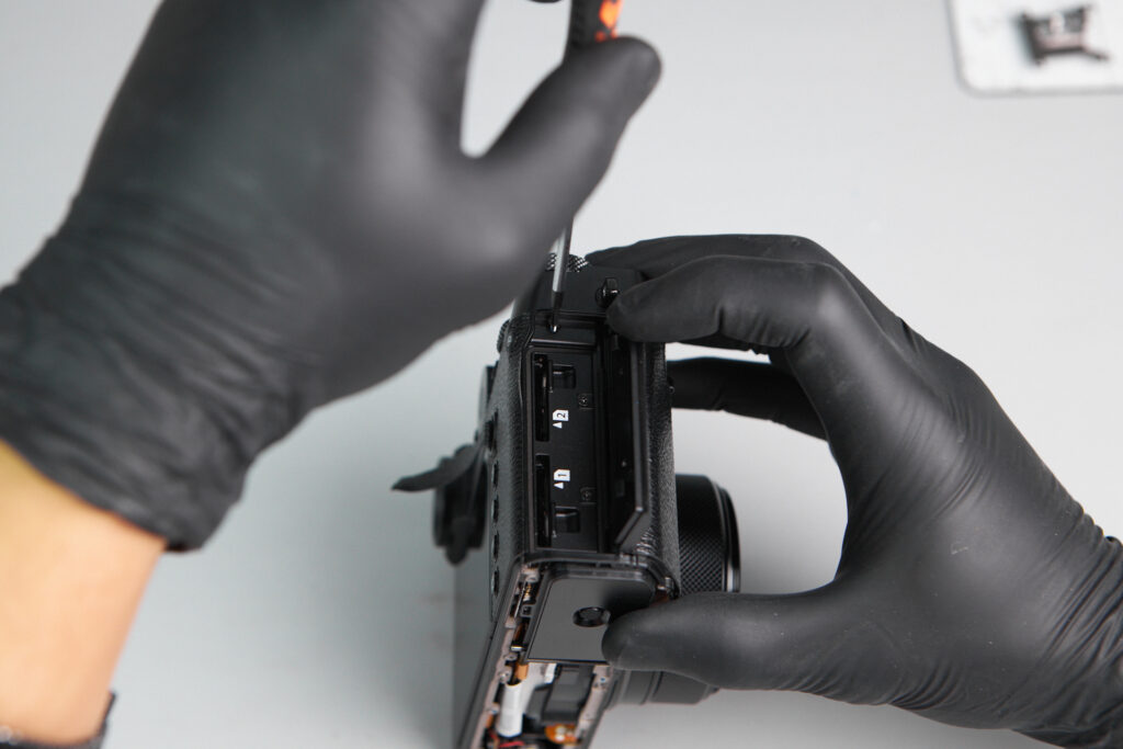
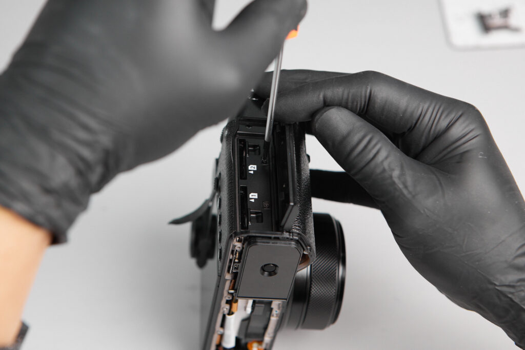
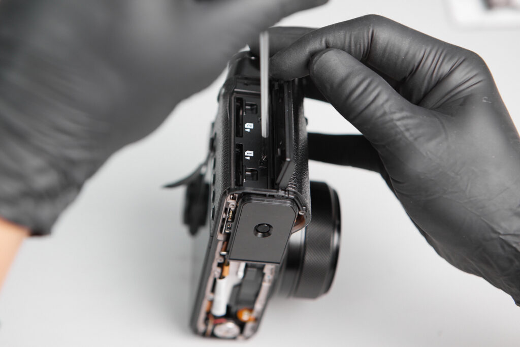
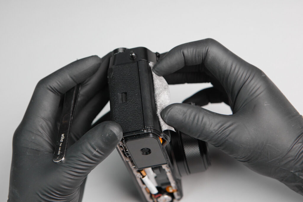
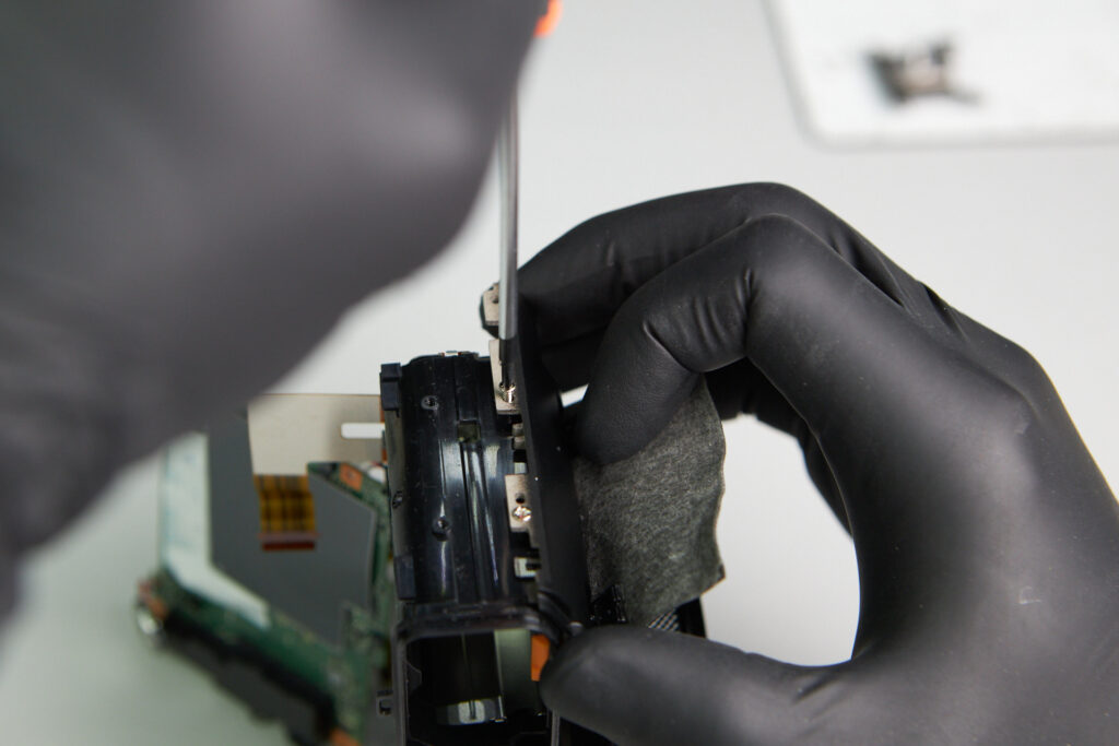
Still on the card slot side of the camera, peeling part of the faux leather covering exposed a thin cover. This is quite uncommon in camera design, so it was a surprise to see it here as we were searching for more screws to remove. Only one screw was removed here.
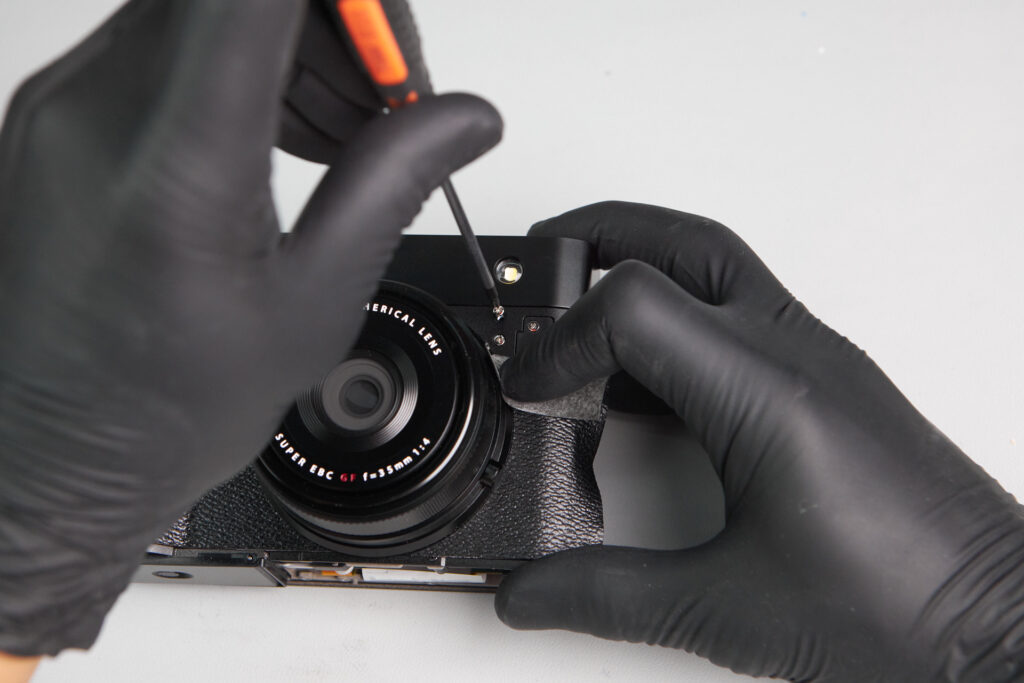
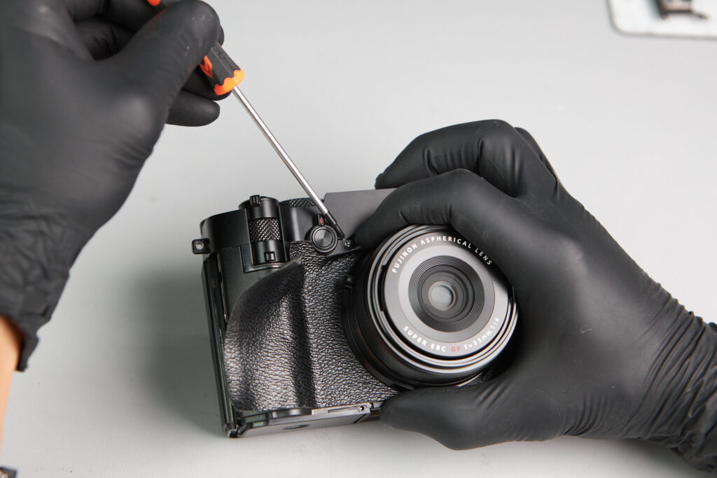
Looking further beneath the leather covering revealed one screw on the front exterior of the camera. From this point on, we were able to start entering the interior of the camera.
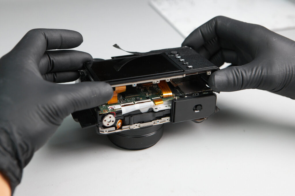
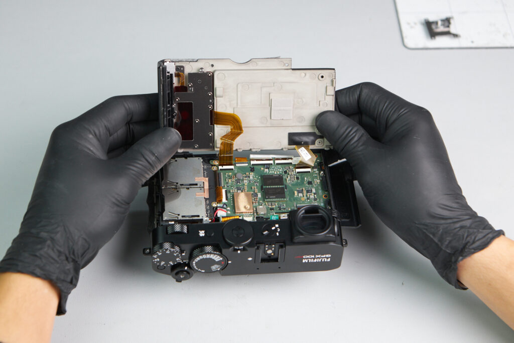
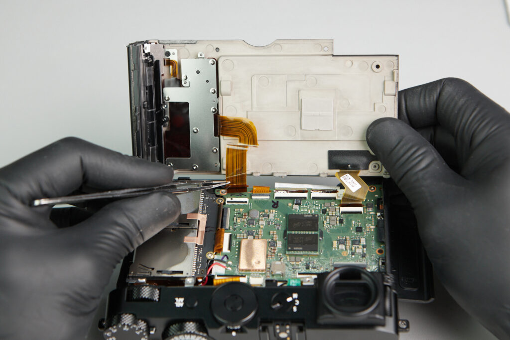
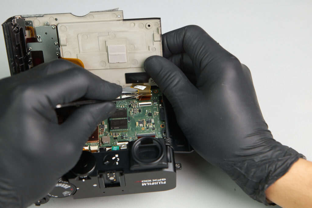
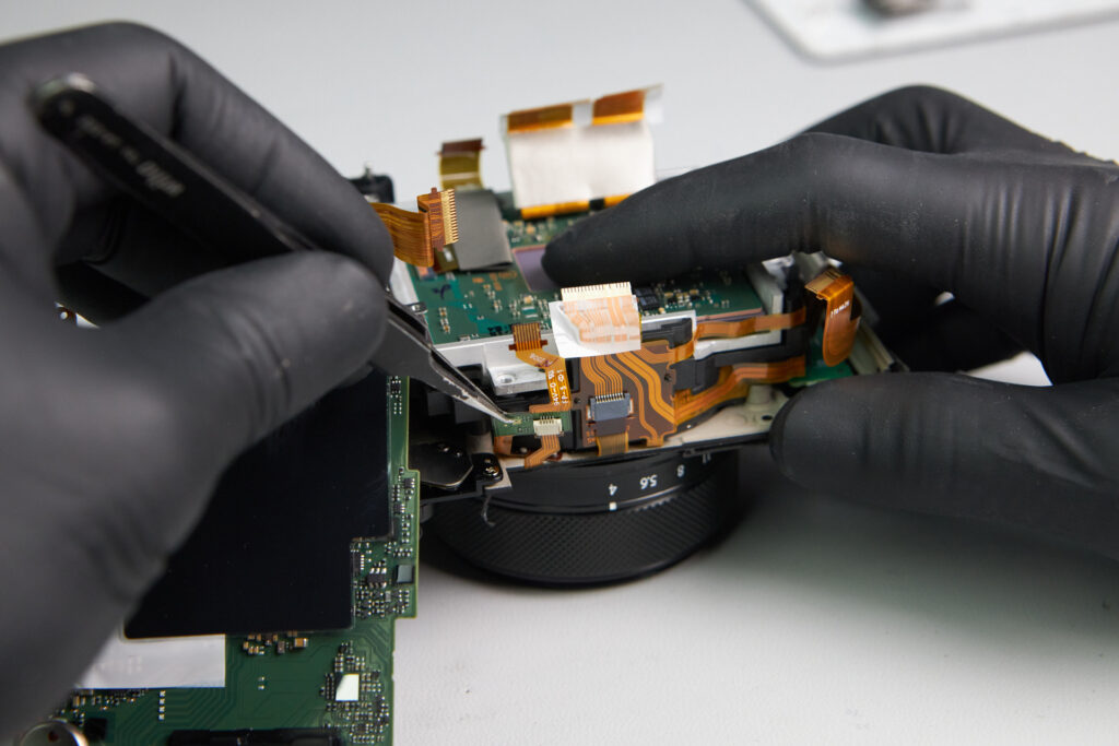
Reaching the interior required us to lift the backside of the camera. The panel was attached with two ribbon cables and needed to be detached before the back panel could be fully removed.
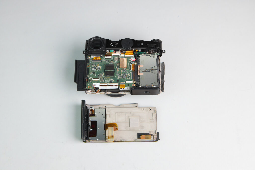
The circuitboard and back panel.
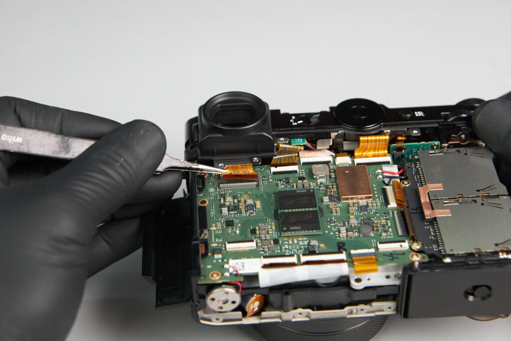
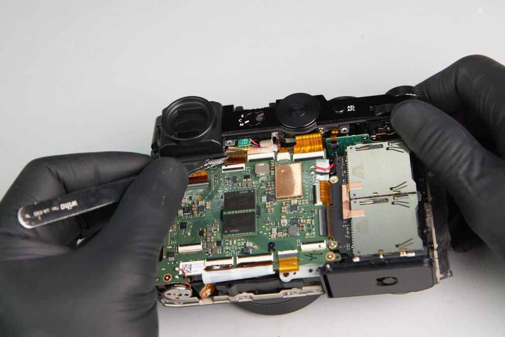
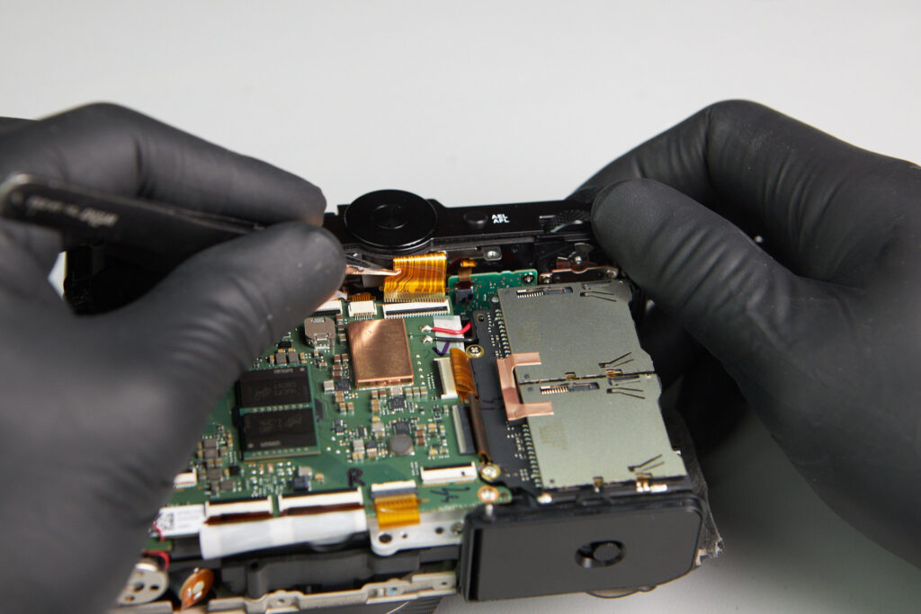
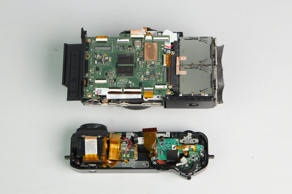
The top panel needed to be removed before we can further remove the circuitboard. Removing three ribbon cables allowed us to detach the top panel.
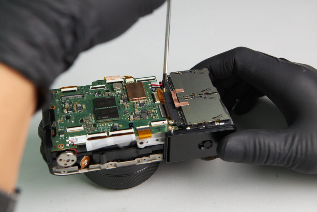
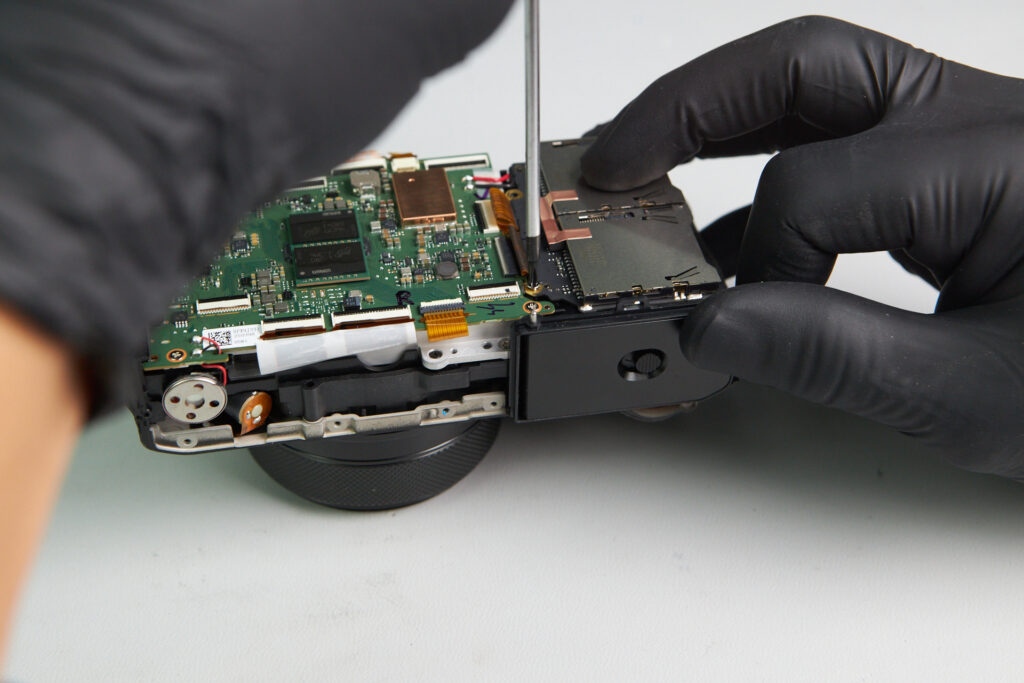
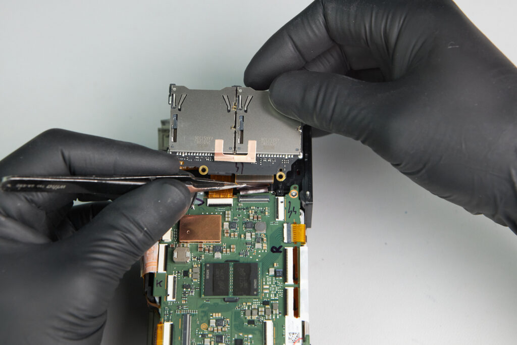
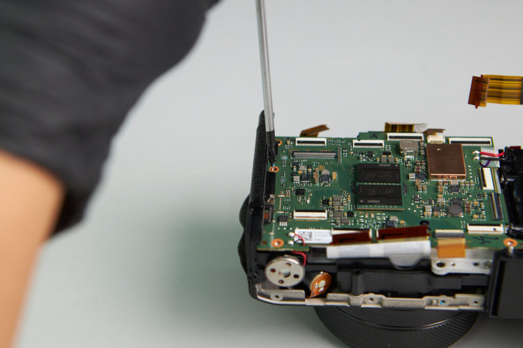
The circuitboard didn’t have clearance for us to start removing it because of the SD card slots. This part was only held down by two screws and two ribbon cable. Removing it gave us space for accessing more of the circuitboard.
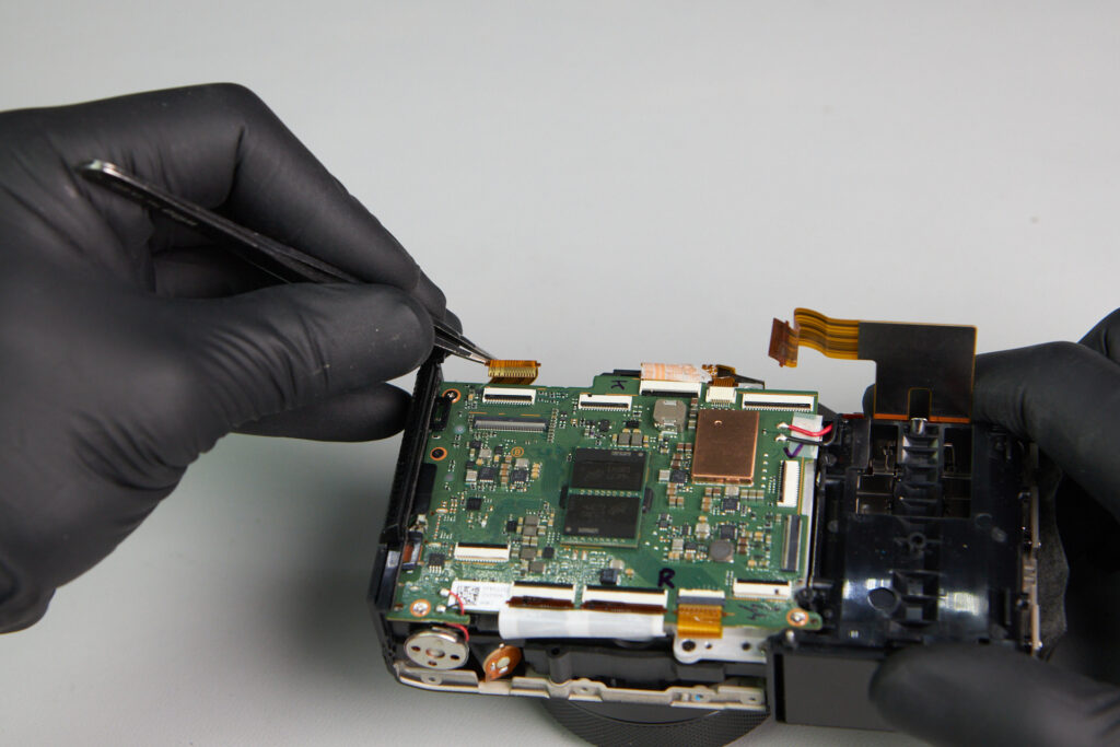
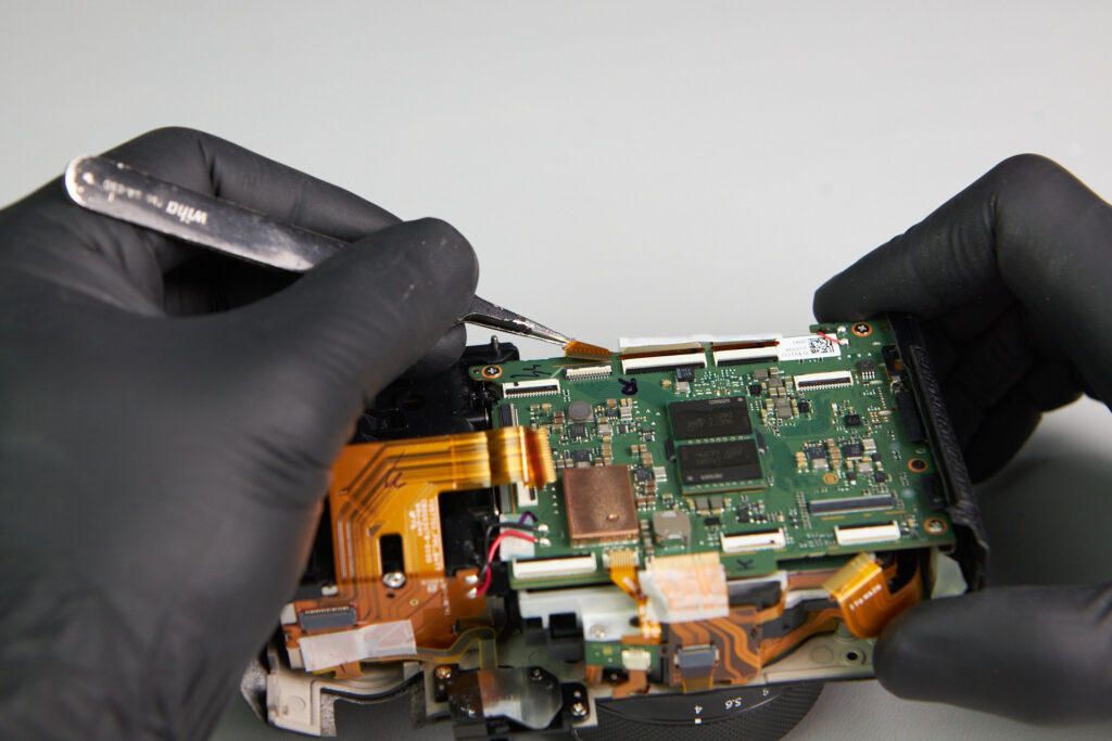
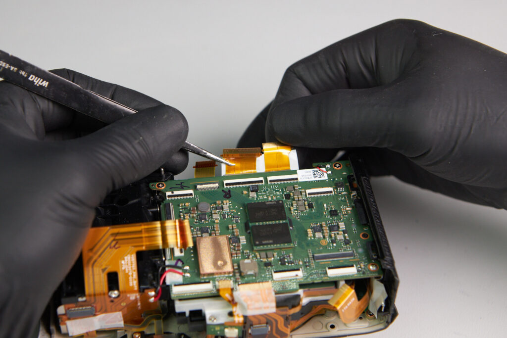
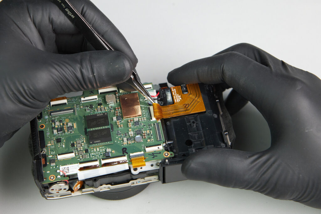
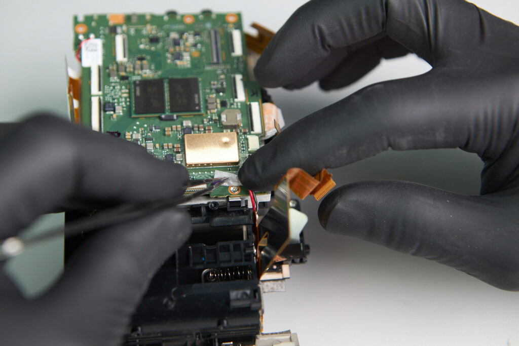
Now with the SD Card slot removed, we can begin extracting the circuitboard. Several ribbon cables surrounded the perimeter of the circuitboard: three on the top and another four on the bottom, as well as one closer to the center.
Four screws were around the perimeter of the circuitboard as well. One of them is hidden underneath tape that holds soldered wiring.
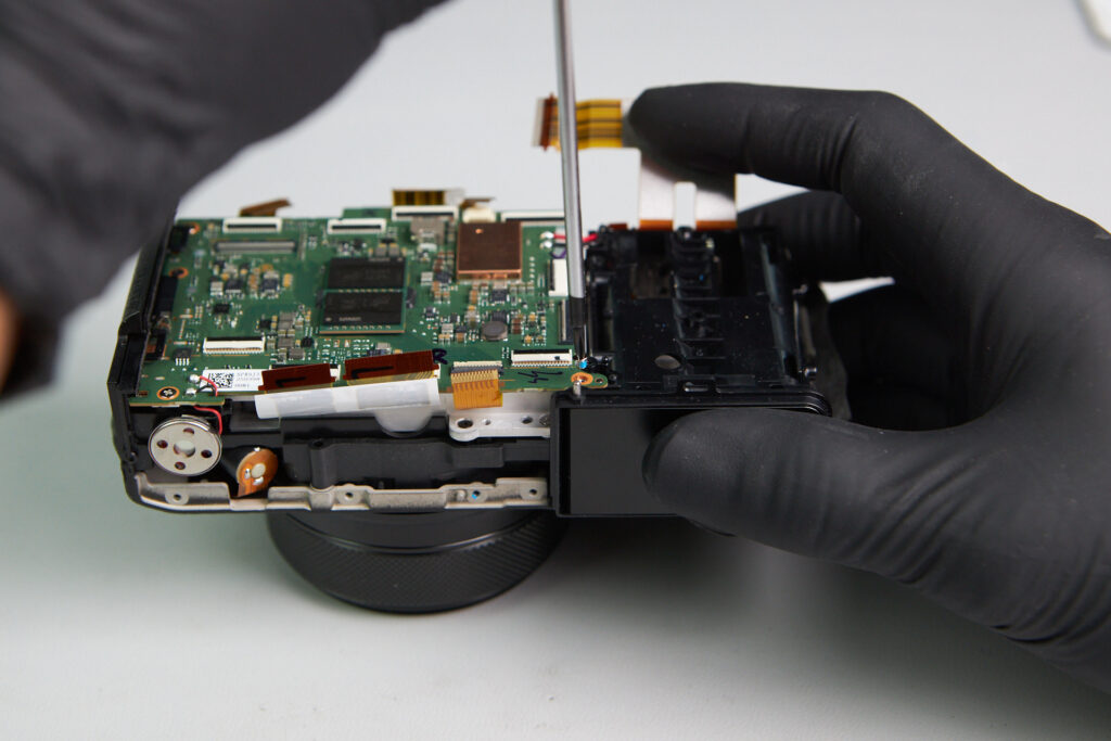
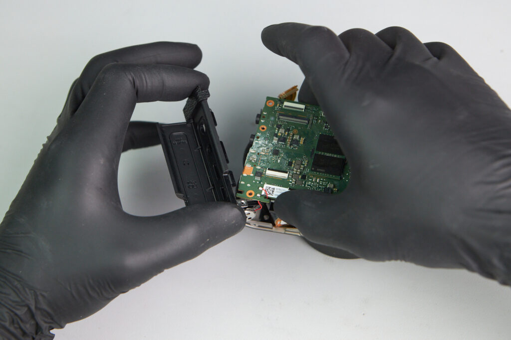
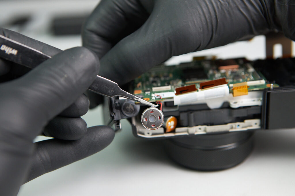
The speaker needed to be removed to disconnect the port cover from the body frame. At this point, we were able to remove the circuitboard.
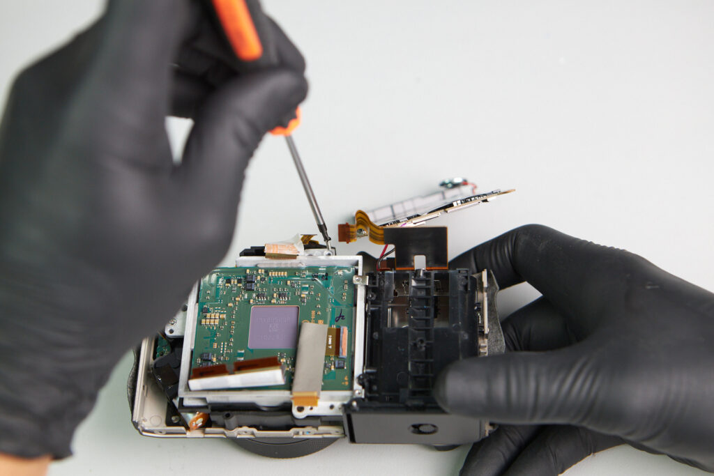
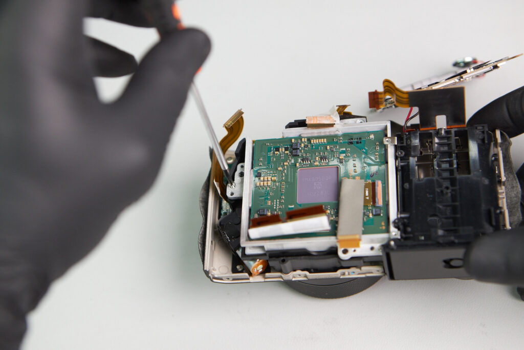
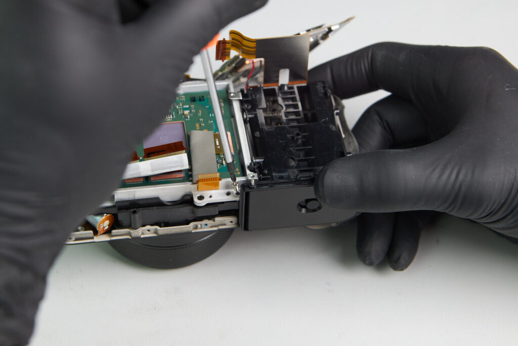
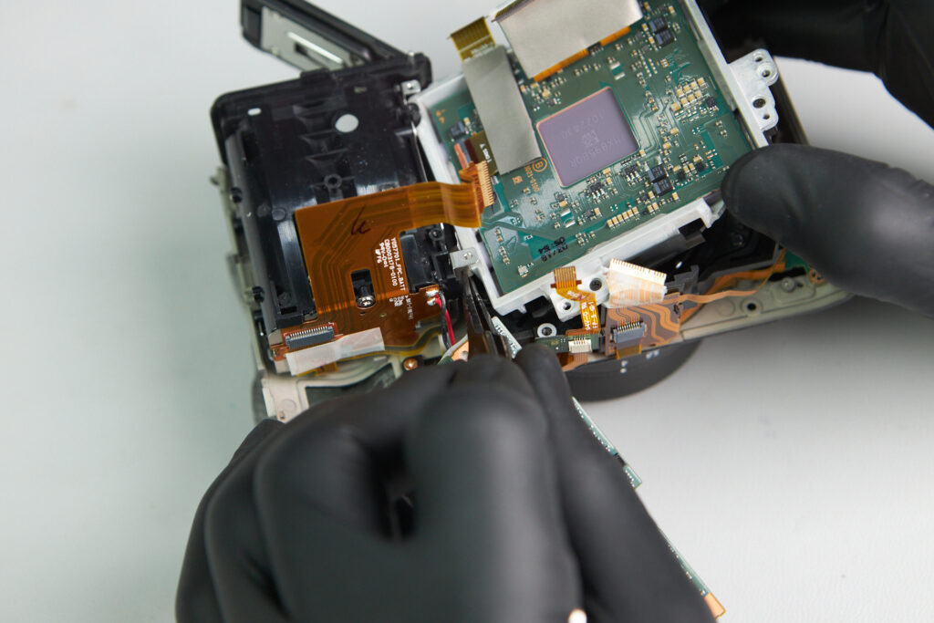
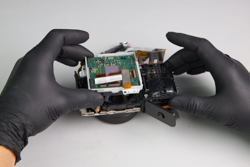
With the circuitboard removed, we could begin removing the sensor apparatus. Three screws held this part in place.
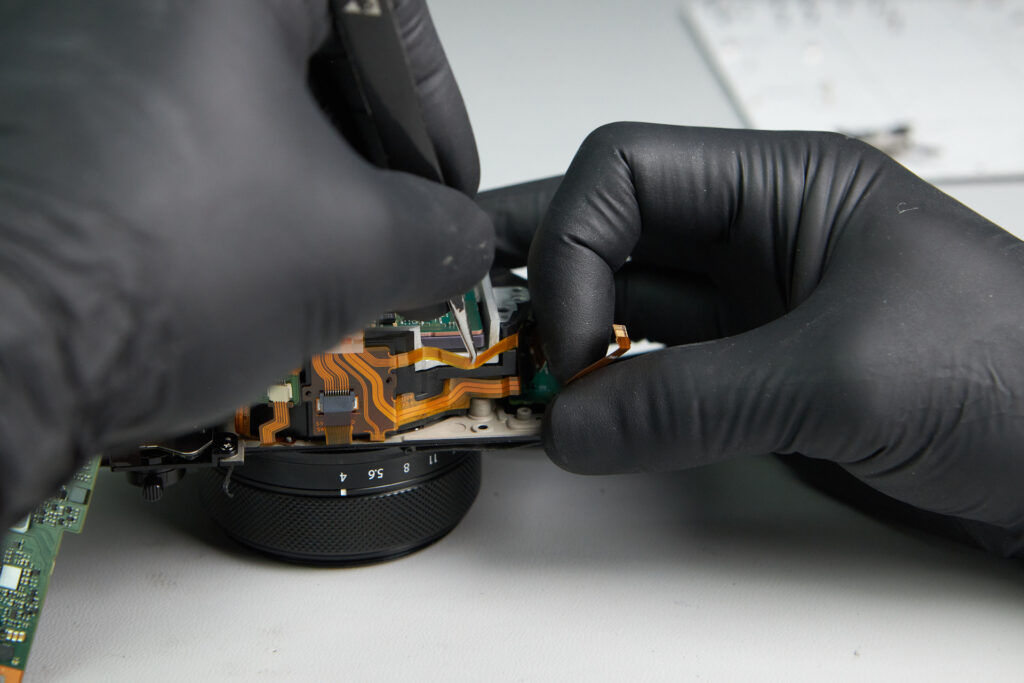
A few other obstacles were in the way of us fully removing the sensor apparatus. One ribbon cable adhered to the edge of the frame
A few hidden screws near the battery compartment needed to be removed to give clearance for the sensor’s removal.
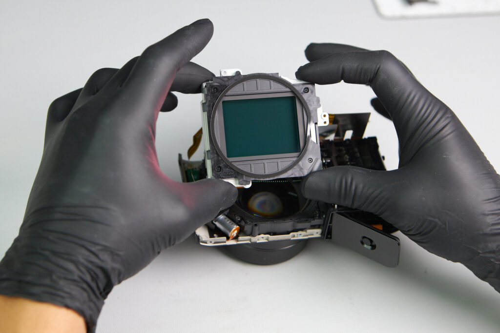
The sensor of the camera.
Thanks for reading.