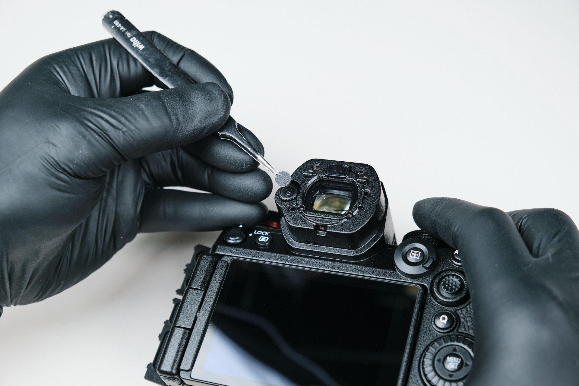
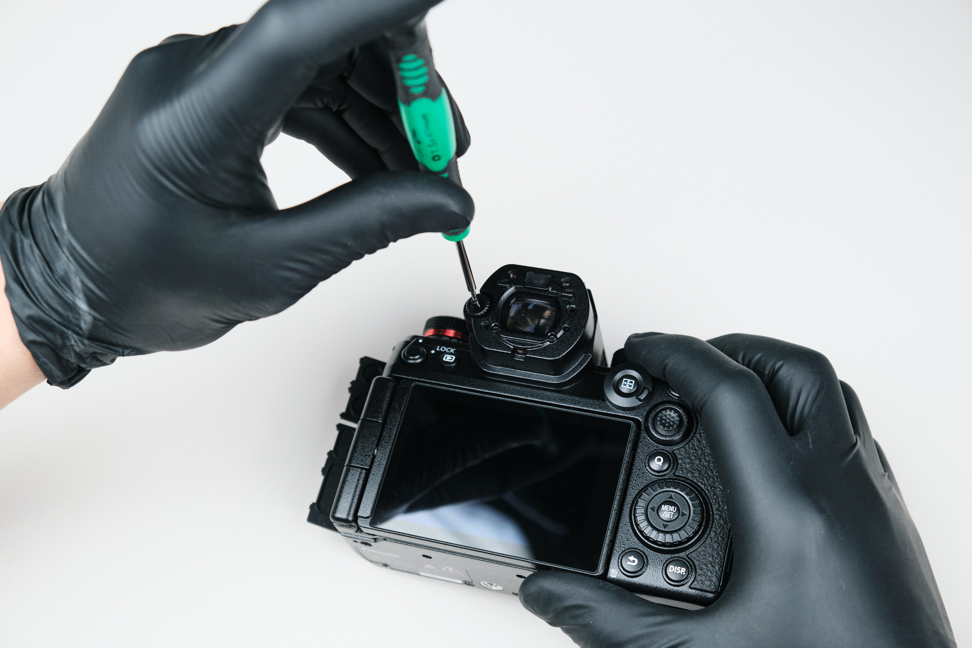
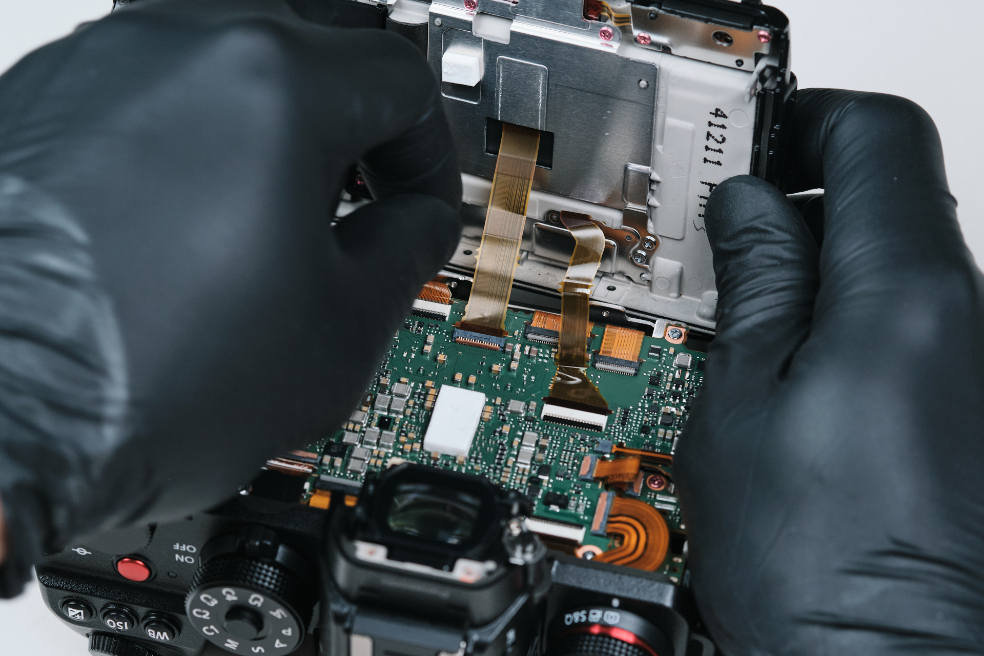
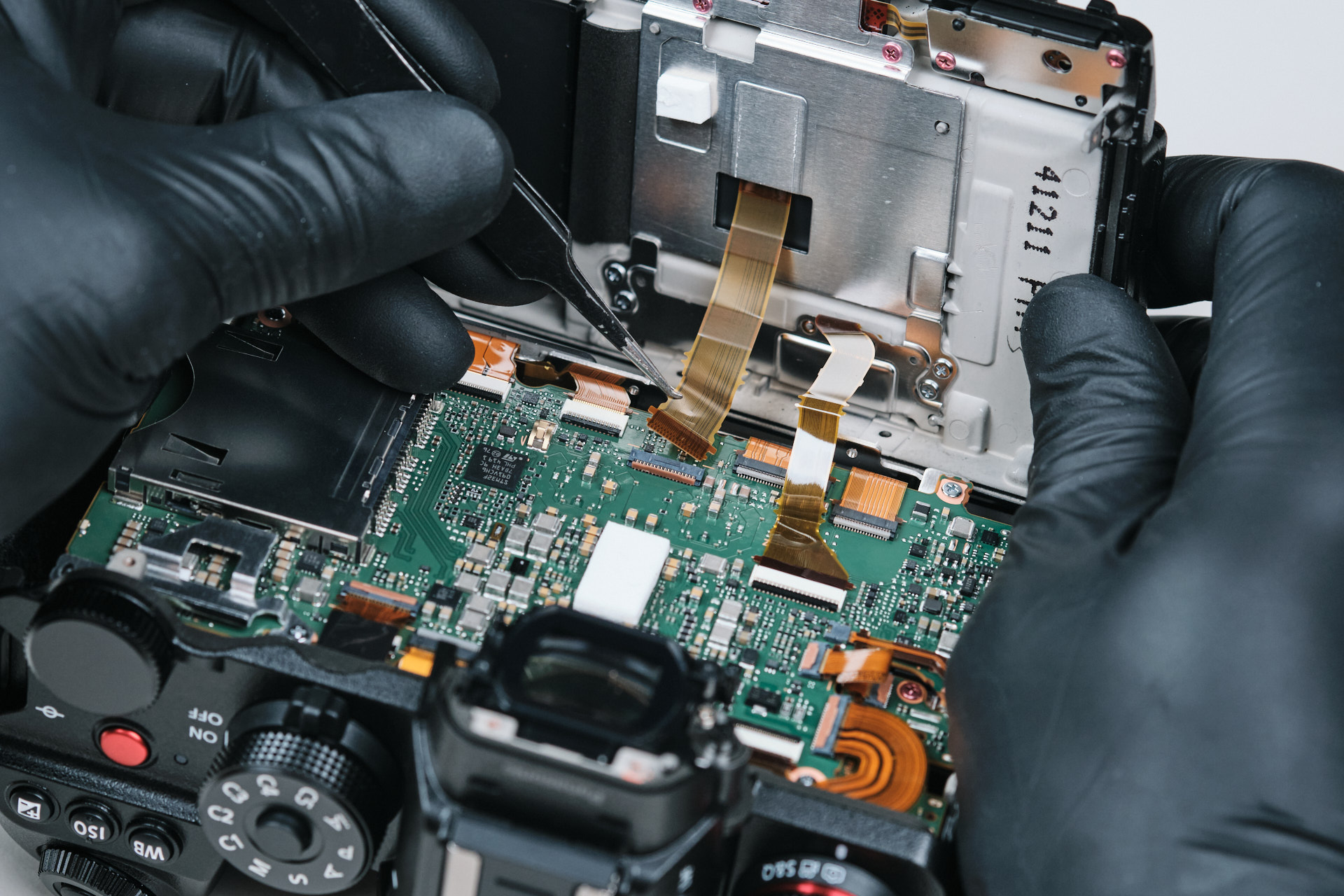
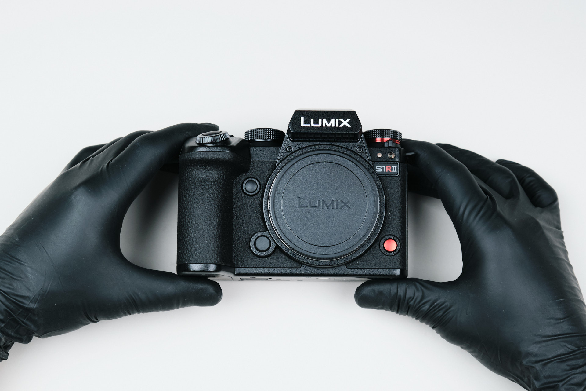
The Panasonic Lumix S1R II was released earlier this year back in February and promises a lot of upgrades from its predecessor, namely a newly developed 44.3 megapixel BSI CMOS image sensor for exponentially better color rendering and overall faster performance, as well as a new image processing engine for improved photo and video capture performance.Â
Panasonic Lumix OLPF/AA Filter Upgrade Compatibility
Although not yet available for the Lumix S1R II, we currently offer an OLPF/AA filter upgrade for select Panasonic Lumix mirrorless cameras. This includes the Panasonic Lumix S1, S1H, S5, S5II, S5IIx, S9, GH6, and BS1H (this service is also offered for the Sigma FP, Nikon Z6 III, and Sony A7IV). This service improves camera performance by dramatically reducing moire.
Starting the Panasonic Lumix S1R II Disassembly
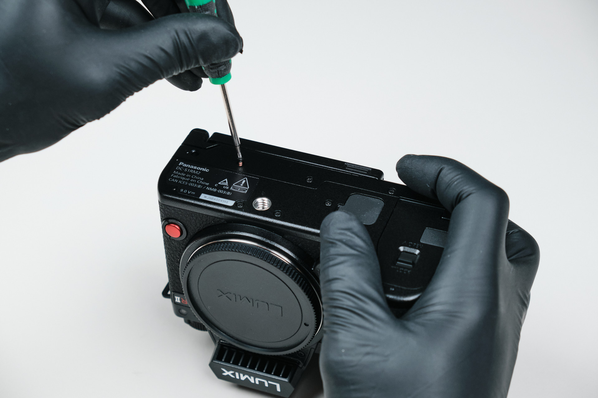
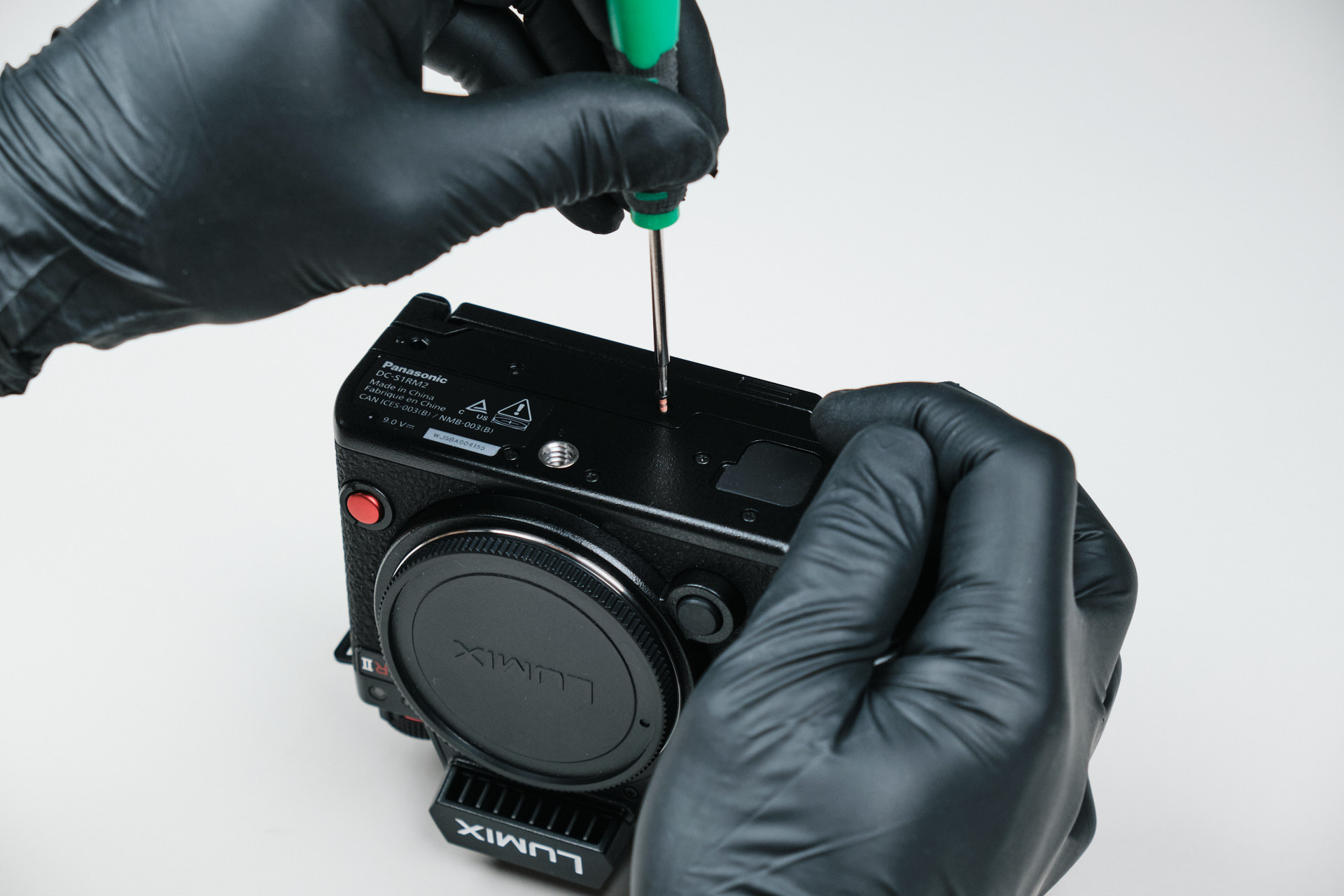
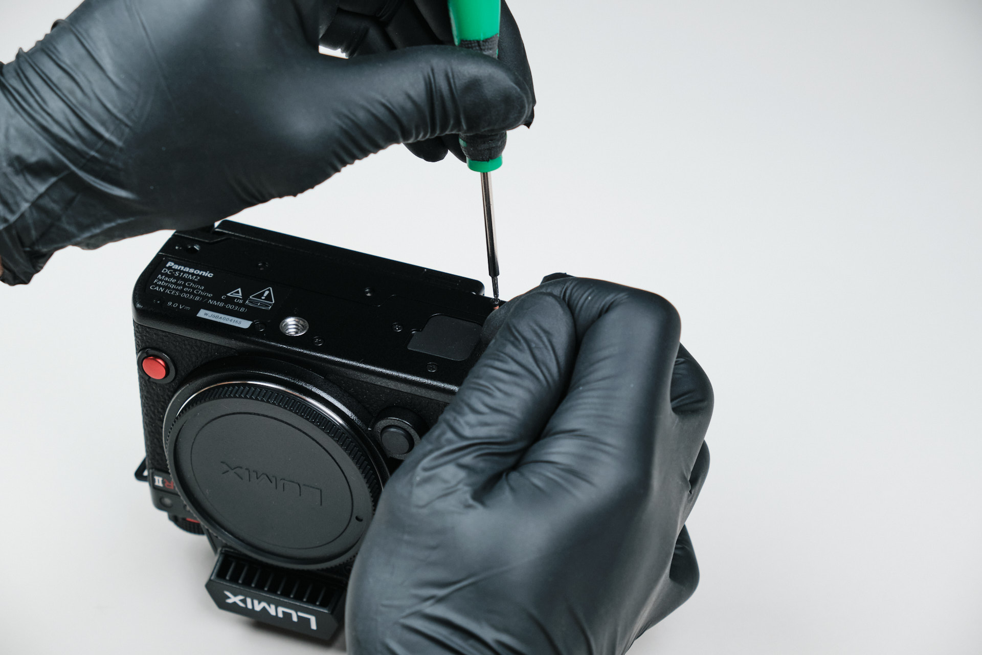
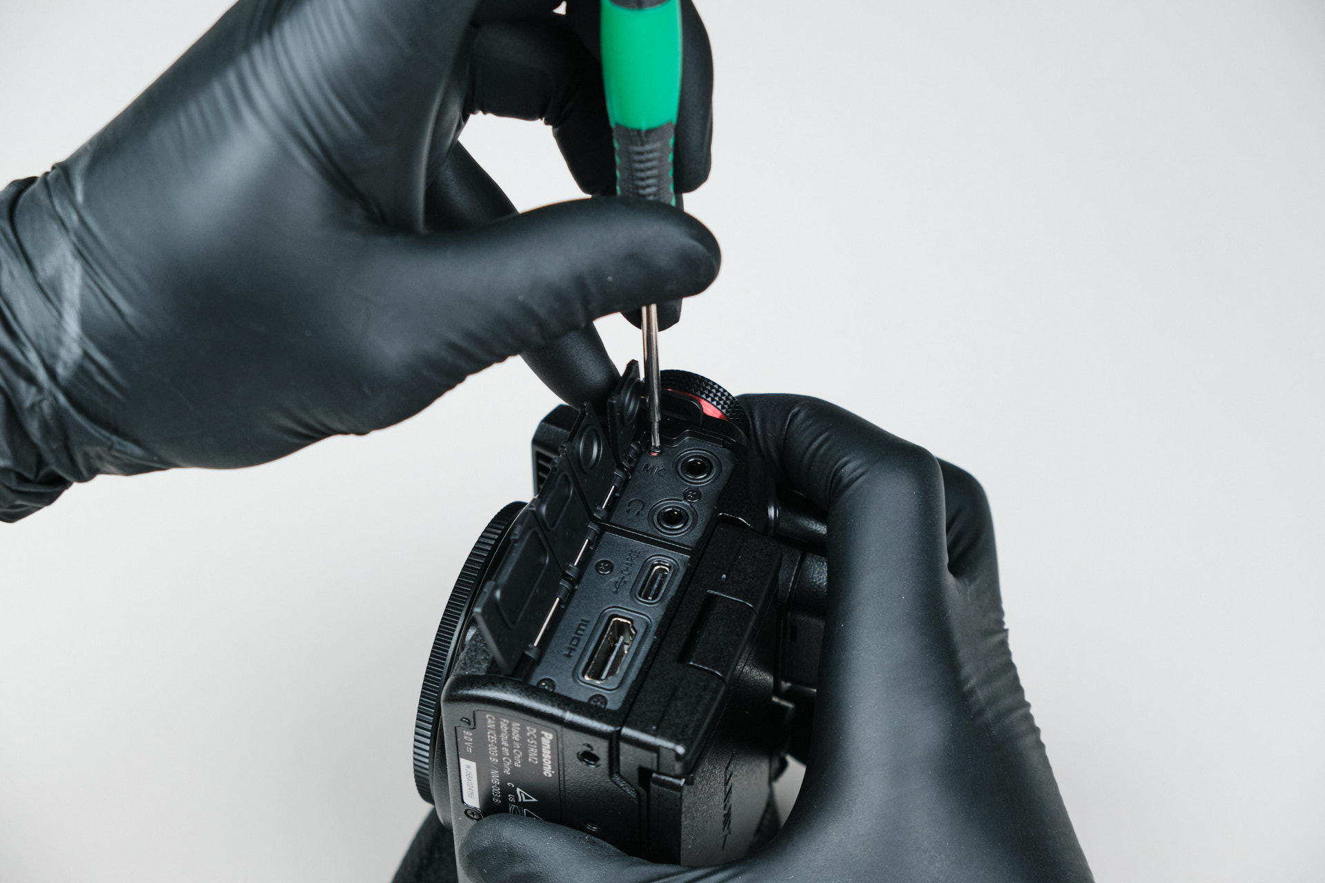
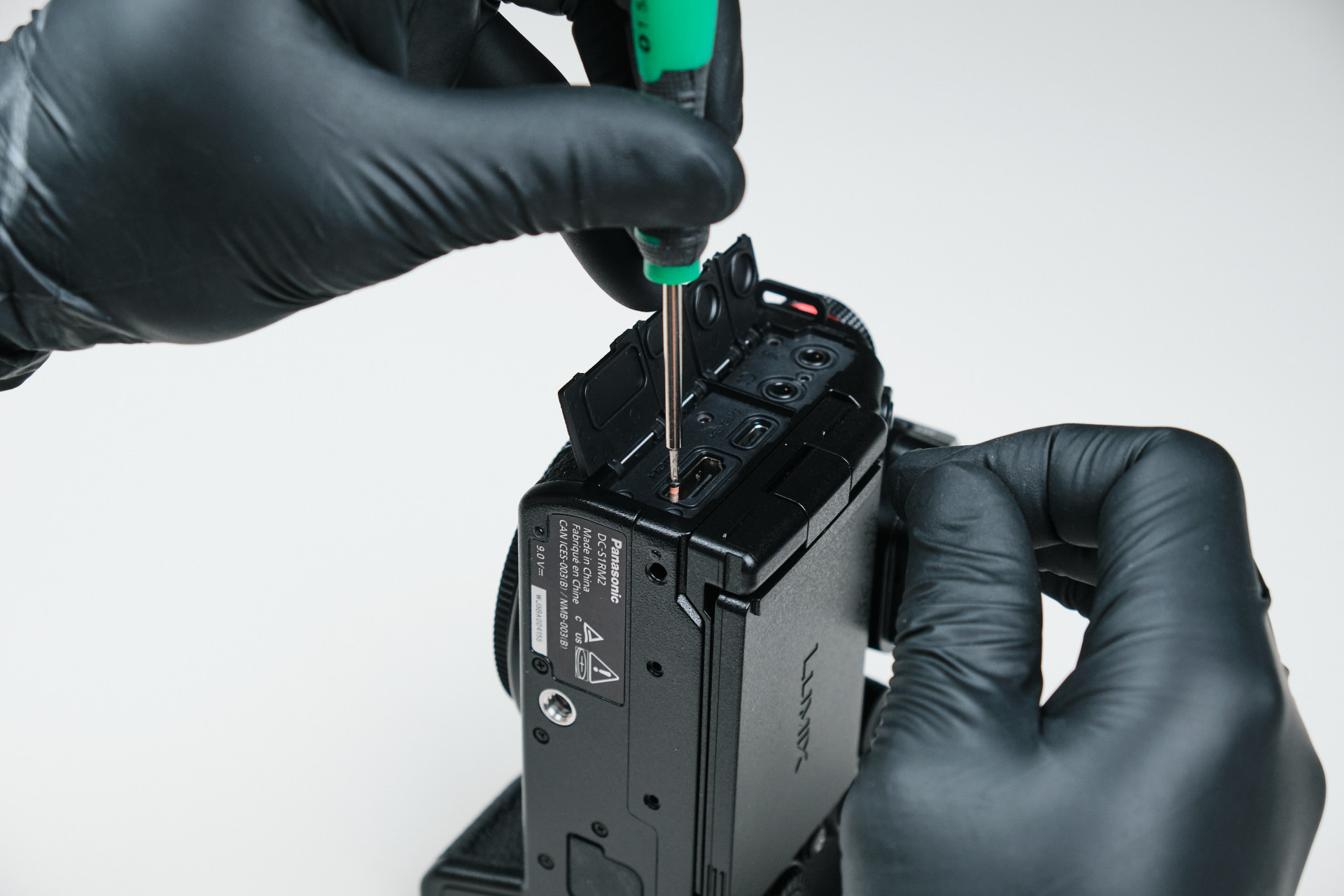
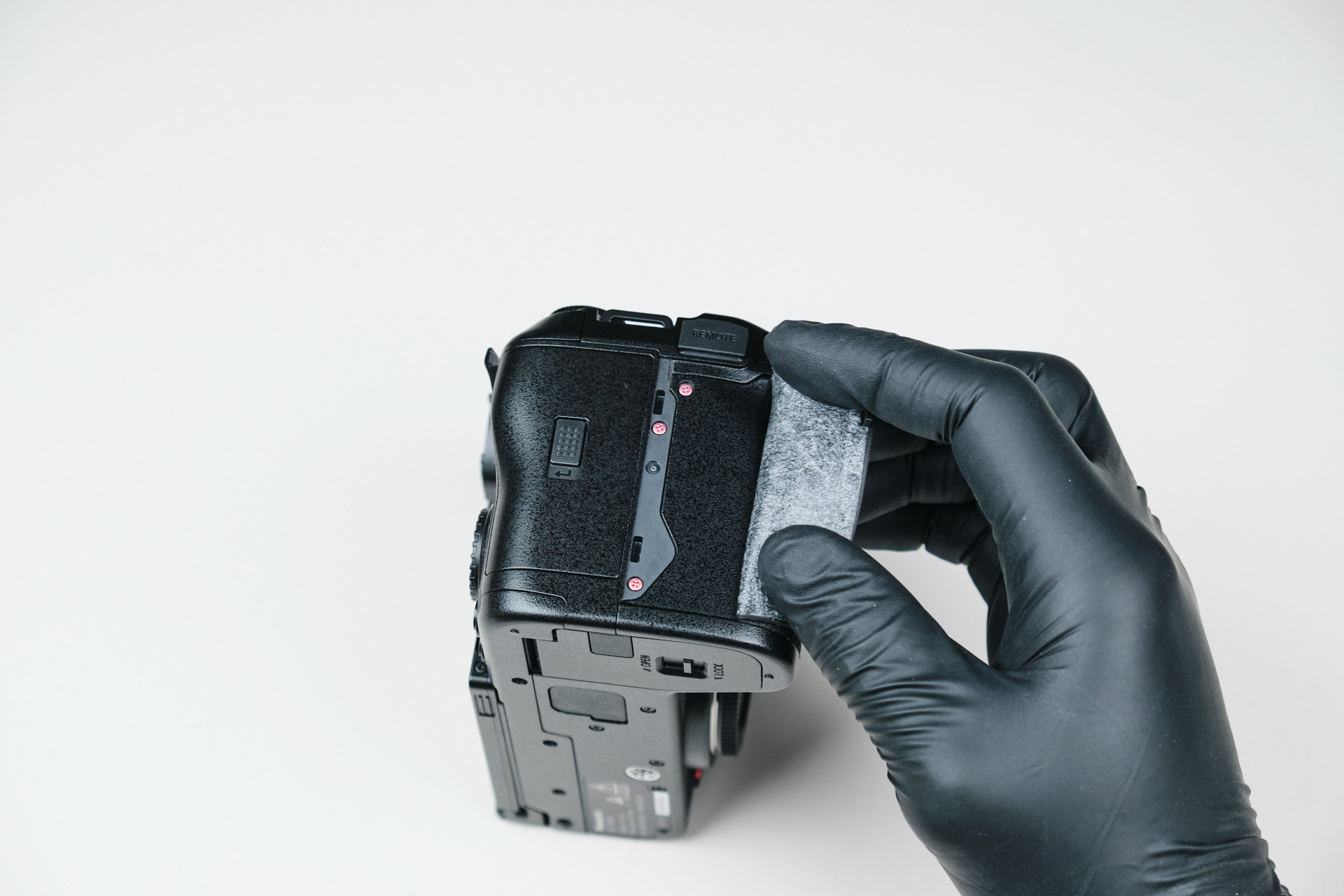
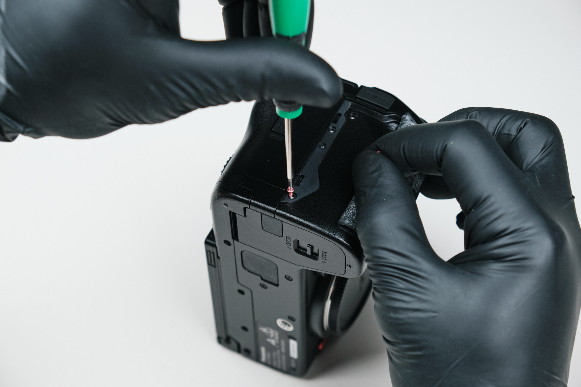
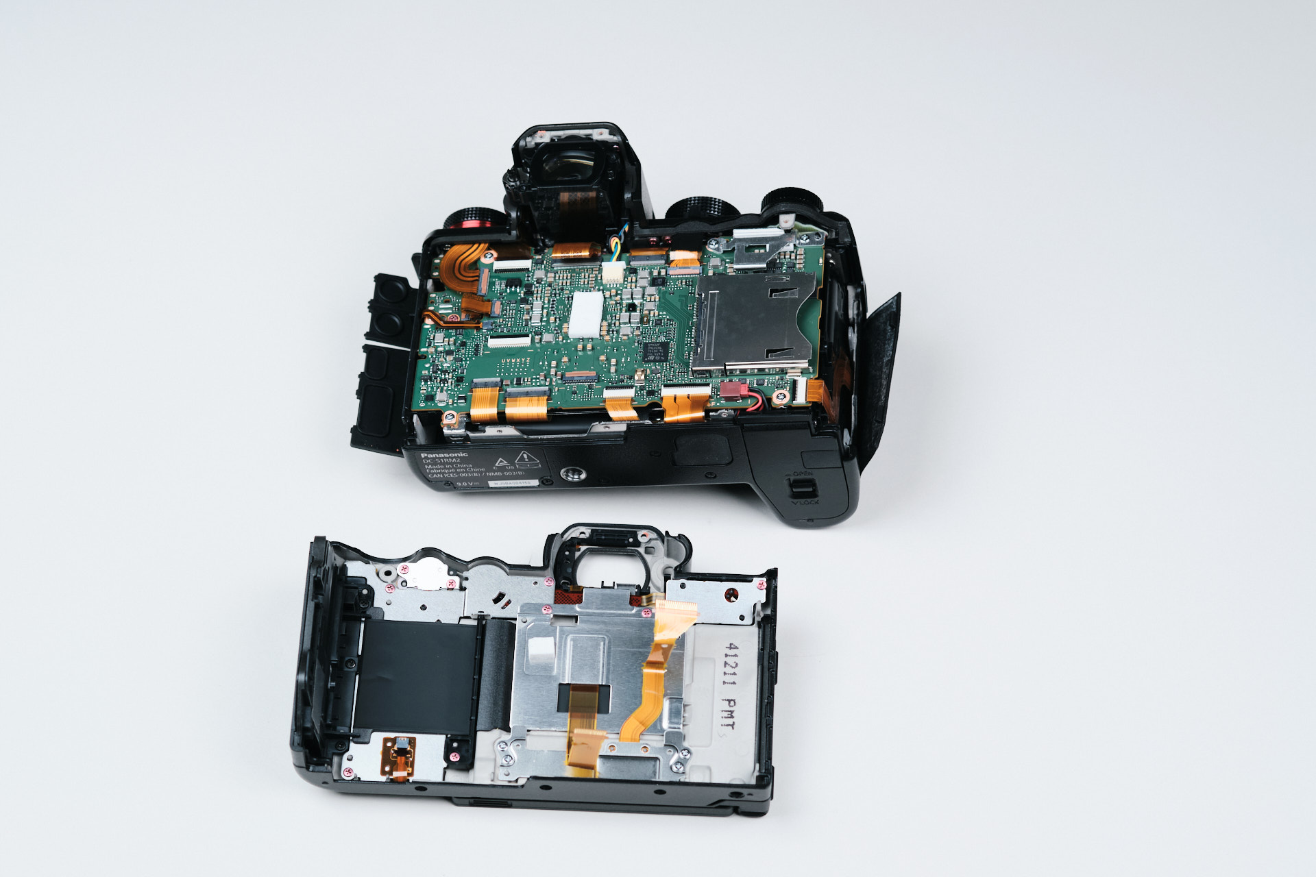
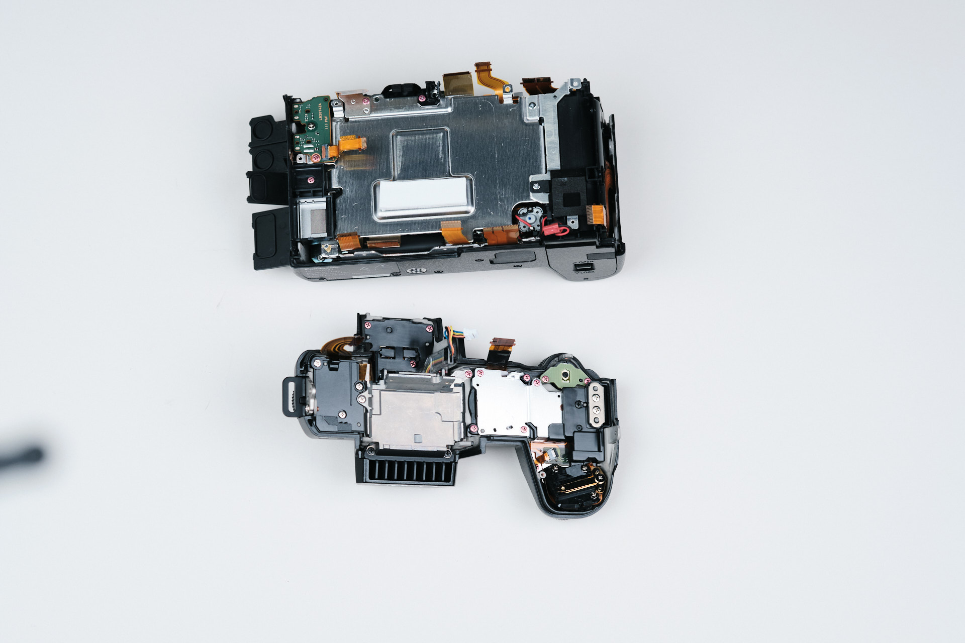
The disassembly and teardown process begins at removing the baseplate for nearly all cameras. However, we noticed that the S1R II doesn’t have a dedicated baseplate piece. If you look closely at the images, you can see that there is a long gap running across the bottom of the camera. This is actually the split between the front and rear panels of the camera. With that in mind, we removed three screws from the bottom of the rear backplate, then moved on to the next part.
Removing the Viewfinder Eyecup
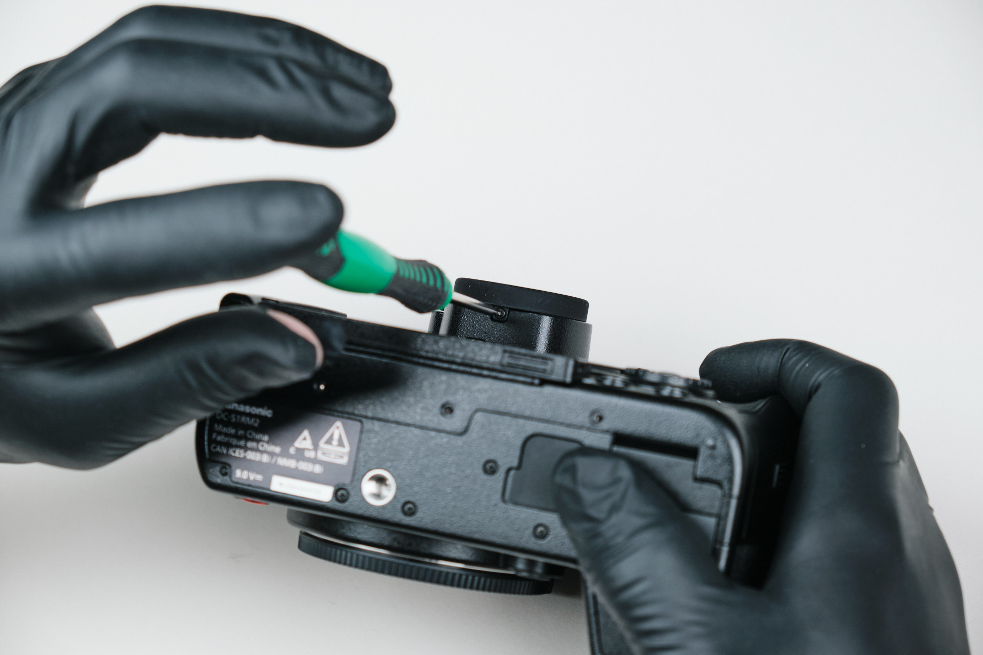
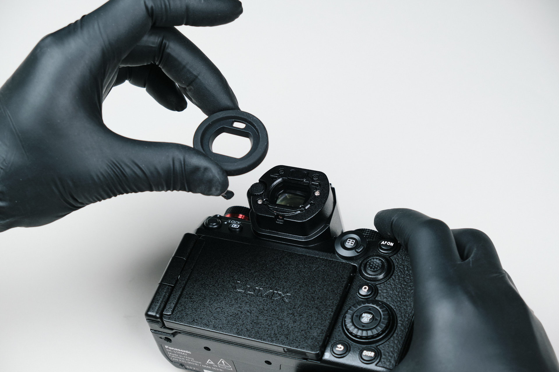
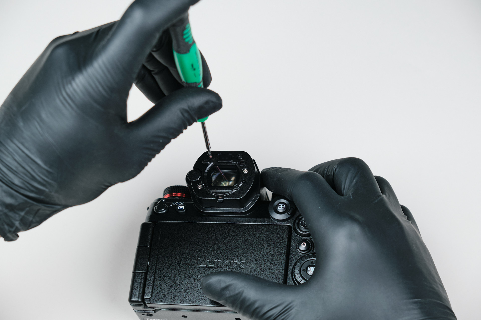
Next, we removed the eyecup of the viewfinder. Unlike most cameras where the eyecup is a squeeze-and-slide removal, the eyecup here is fastened from the underside of the viewfinder with one screw.
Removing the Rear Backplate Screws
Removing the eyecup revealed four screws by the viewfinder. The camera’s viewfinder seemed to be a part of the camera’s rear backplate, revealing that the entire backplate frame is one piece. We removed these four screws and moved on.
Removing Port Side Screws and Body Frame Screws
On the camera’s left, the port side, there were five screws underneath the port covers. Removing these screws did not allow us to remove a “port side panel,” meaning that this side of the camera was also a part of the camera’s one piece of frame. We had yet to find out if it would be a part of the front plate or rear backplate.
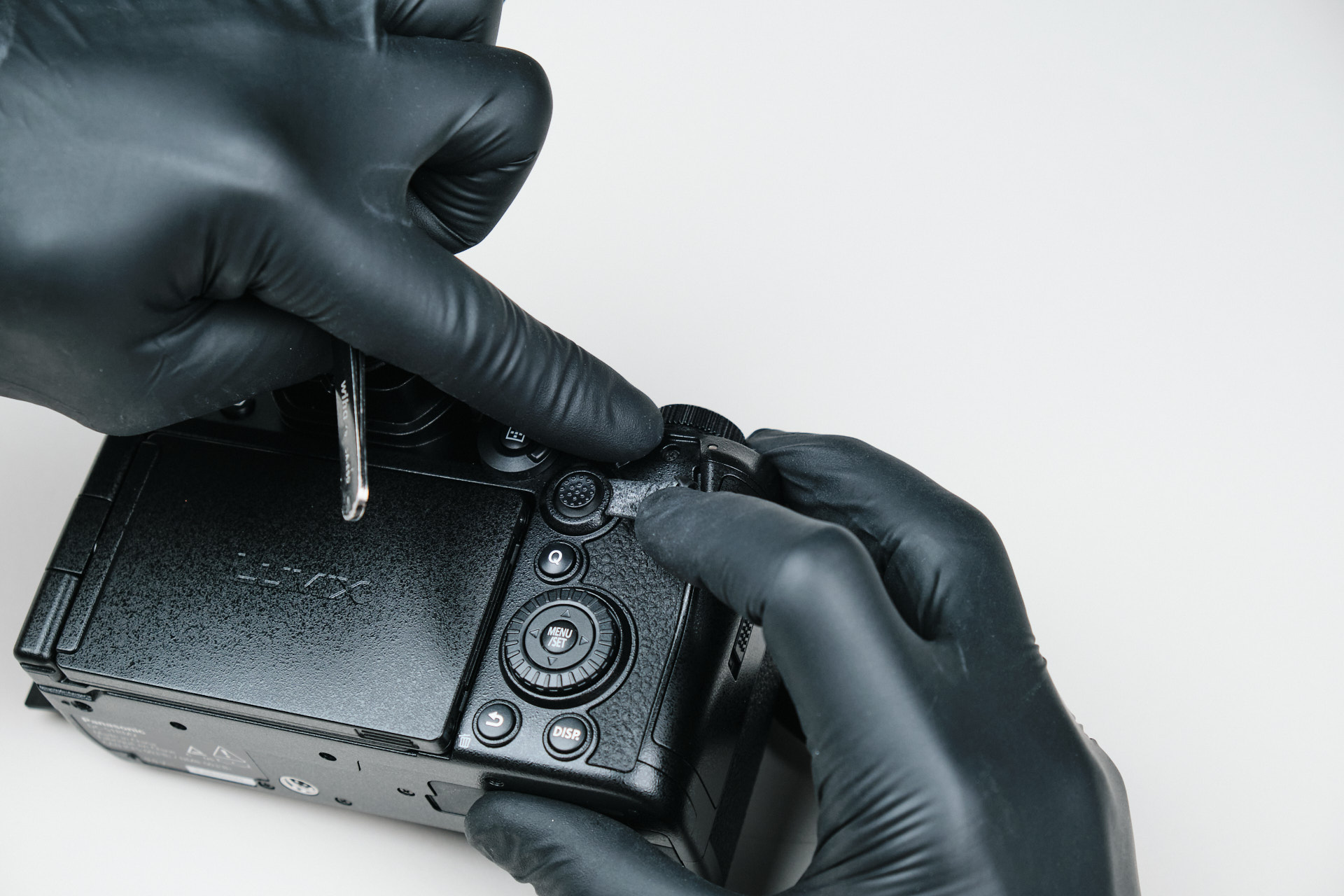
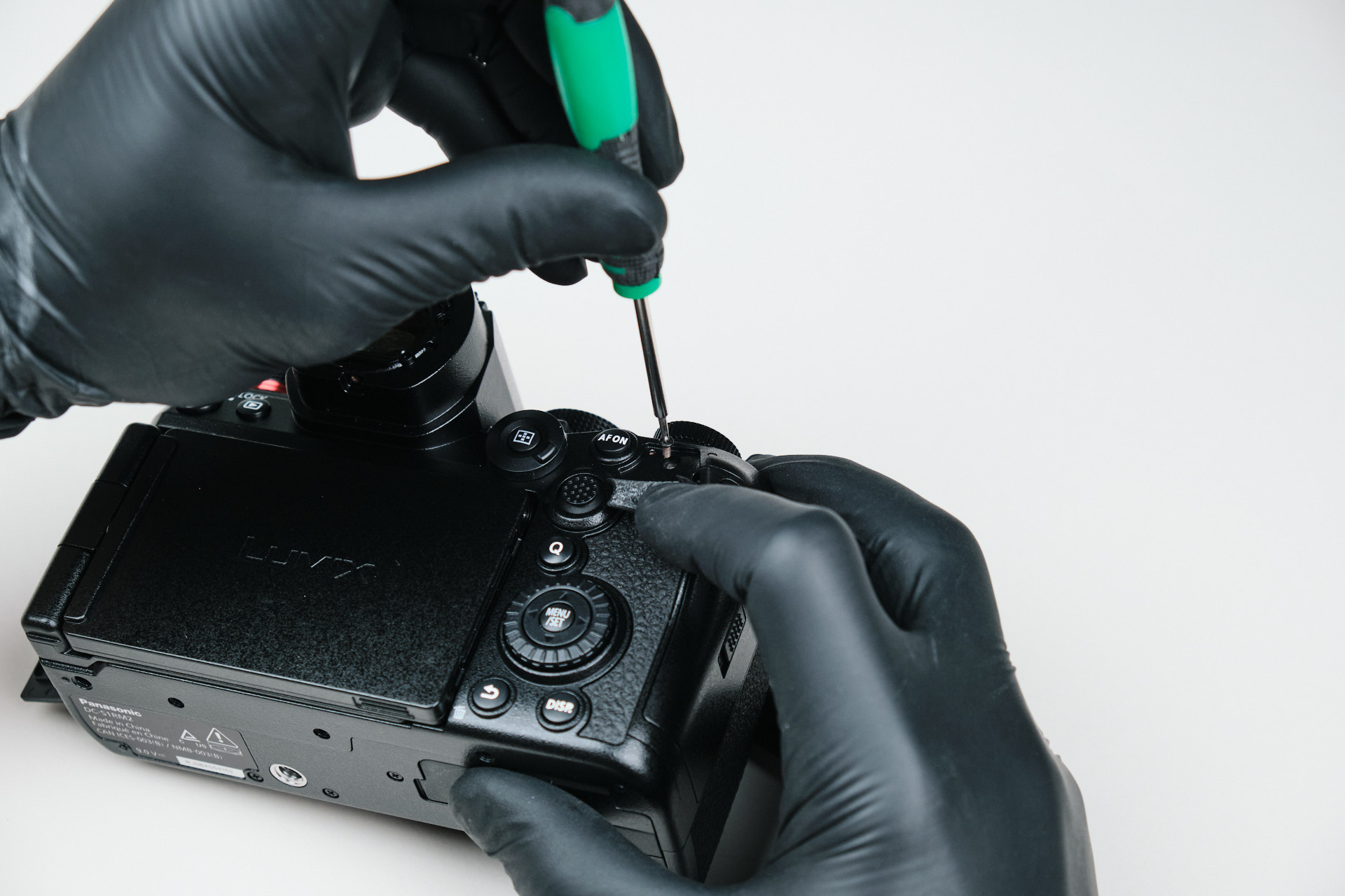
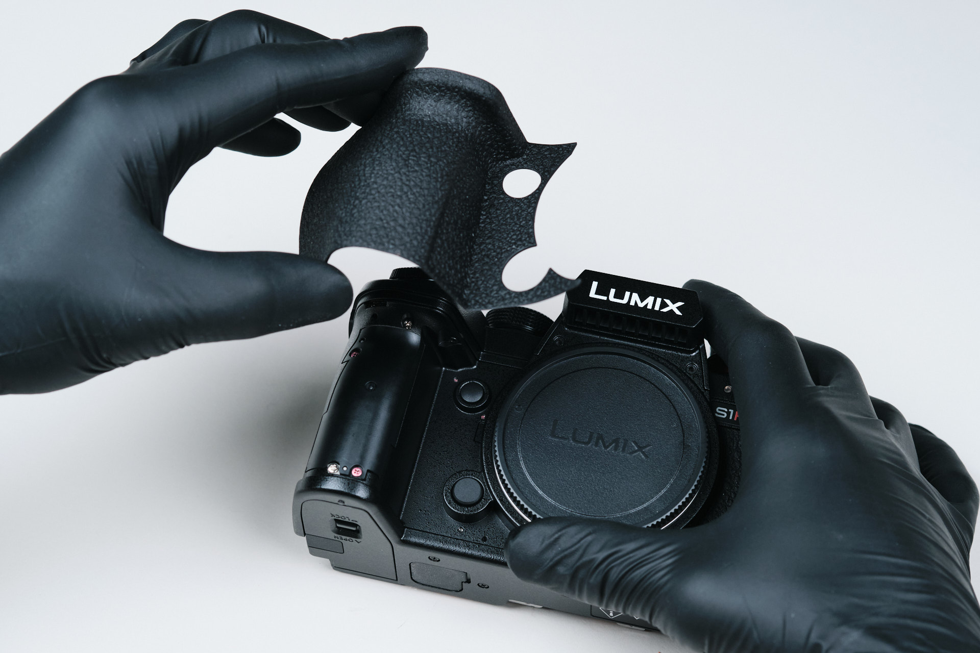
Finding Hidden Screws Under the Leather Skin
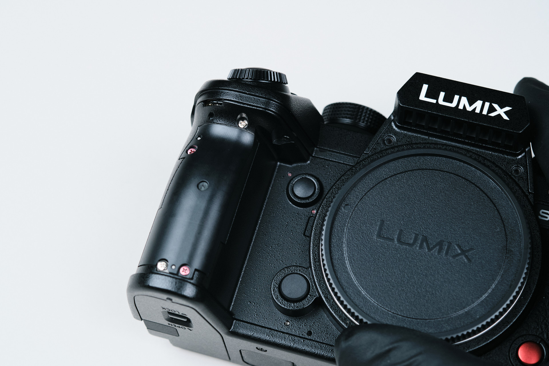
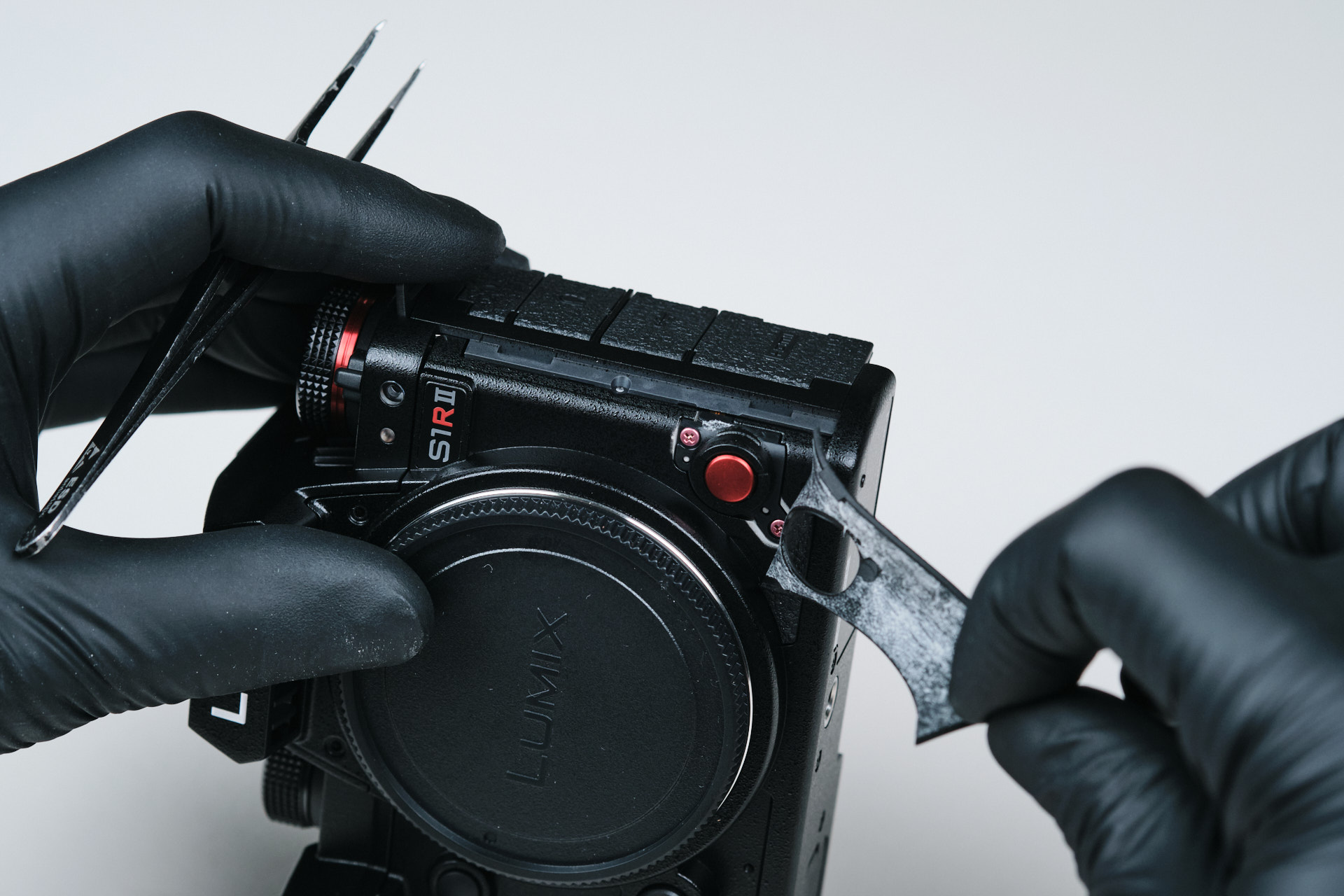
At this point, we removed most of the exterior screws that were readily exposed, and so, we went to search for the hidden screws. Typically, screws that keep the camera’s body frame together can be found underneath the exterior leather skin. The first screw we found were on the righthand side of the camera beneath the leather right by the joystick. As we’ll find out later in this article, there are more hidden screws to be found beneath the leather-skin exterior.
On the memory card side of the camera, there were three screws underneath the leather skin.
Removing the Hidden Diopter Screw
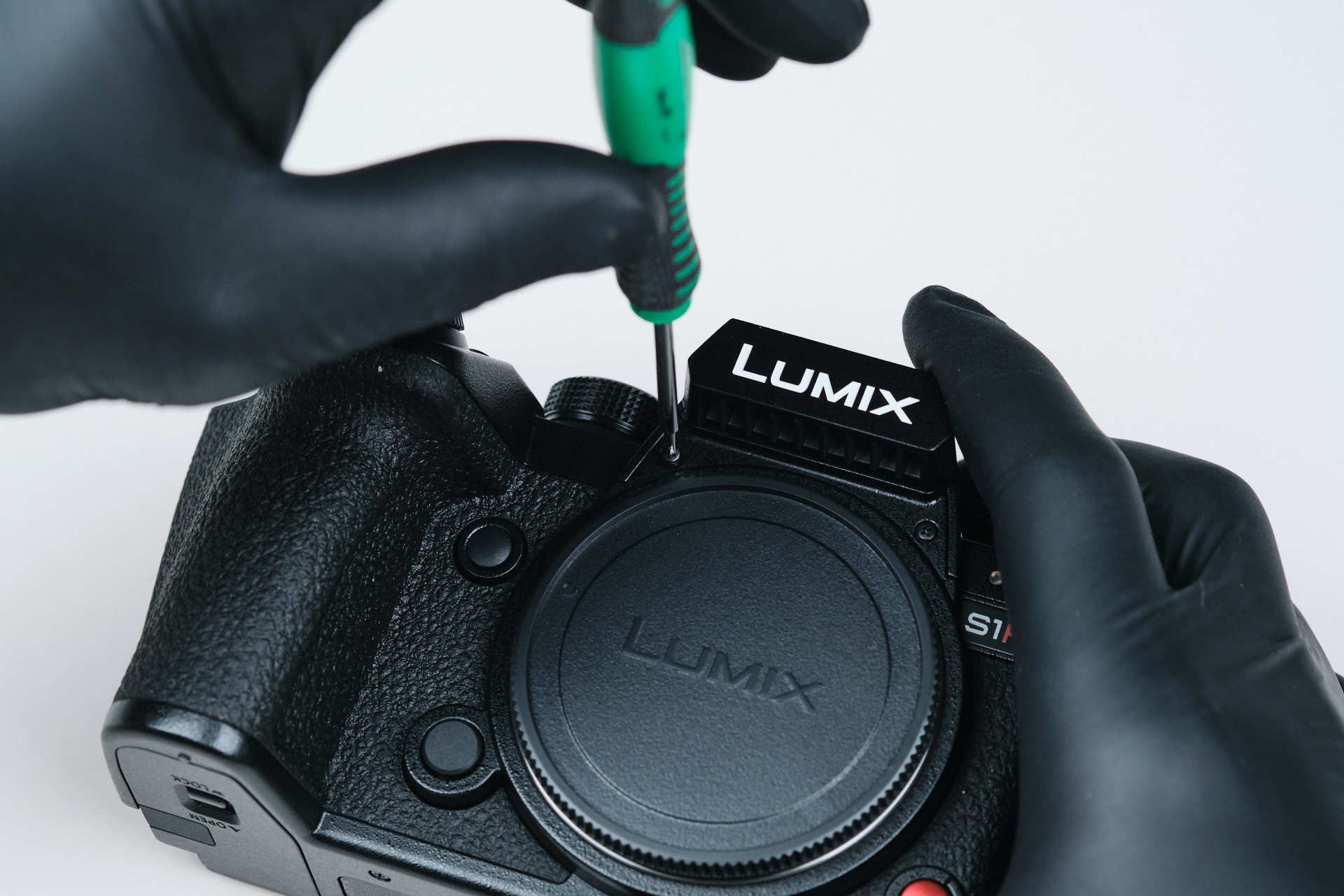
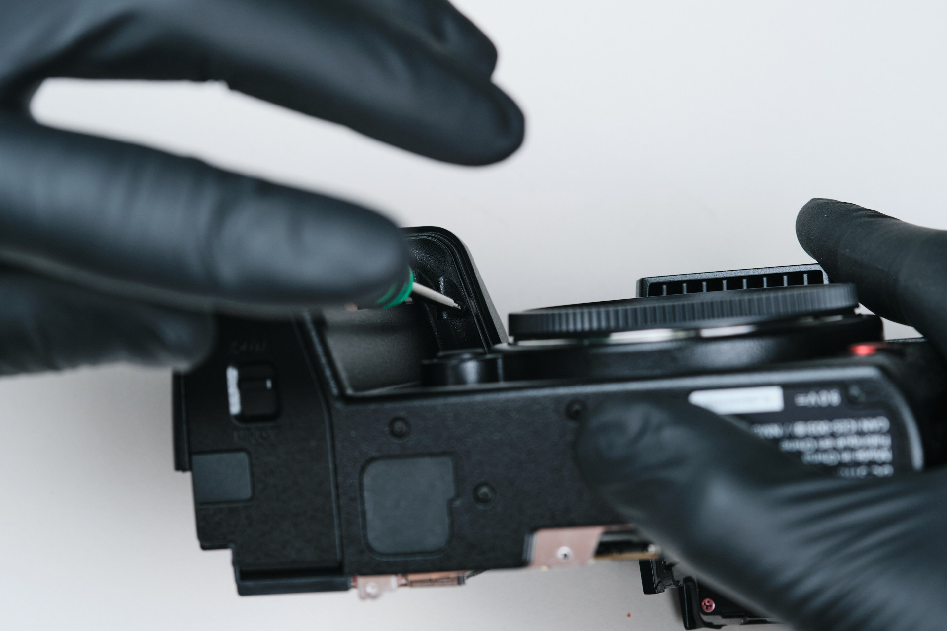
We weren’t able to open up the camera even after removing the aforementioned screws, but it turned out that we were missing one more screw hidden within the diopter screw. This was the last screw we needed to remove to reach the internal space of the camera.
Opening the Rear Backplate and Ribbon Cables
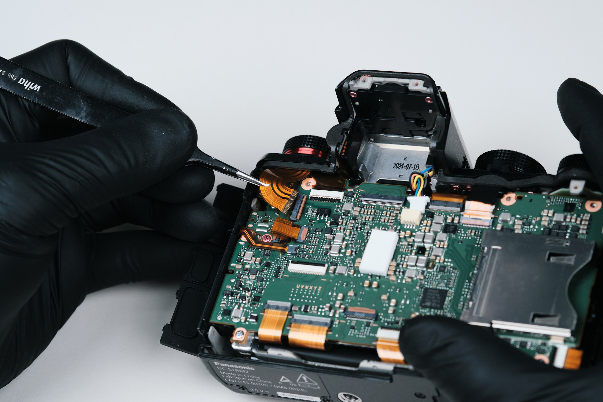
Two ribbon cables within the interior of the rear backplate connected it to the circuitboard. In the third image, you can see that the camera body is comprised of two frame plates, front and back, as opposed to having a dedicated front, back, and baseplate.
Removing the Viewfinder and Internal Connections
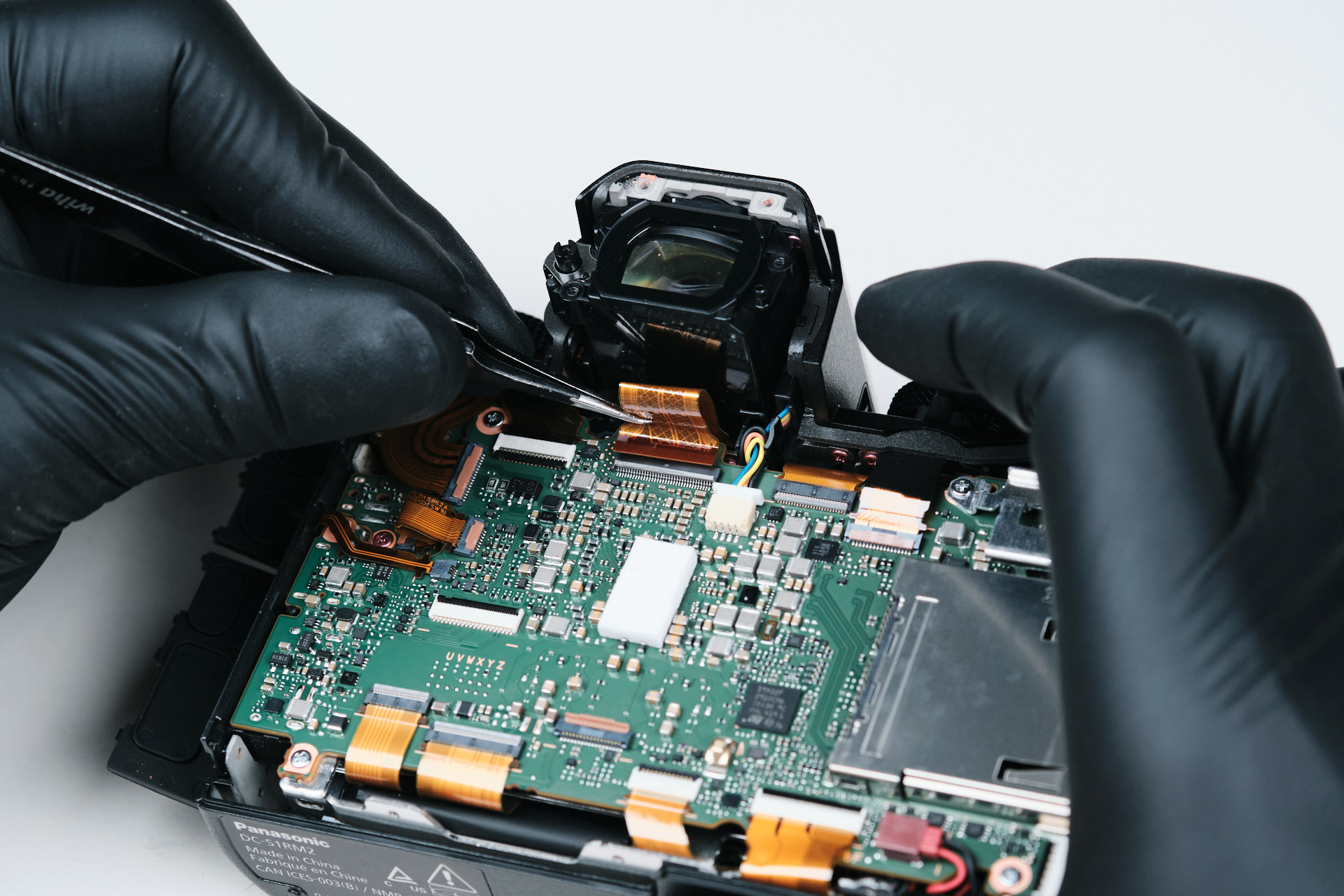
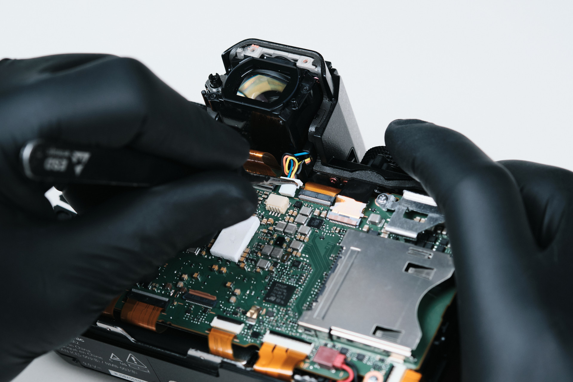
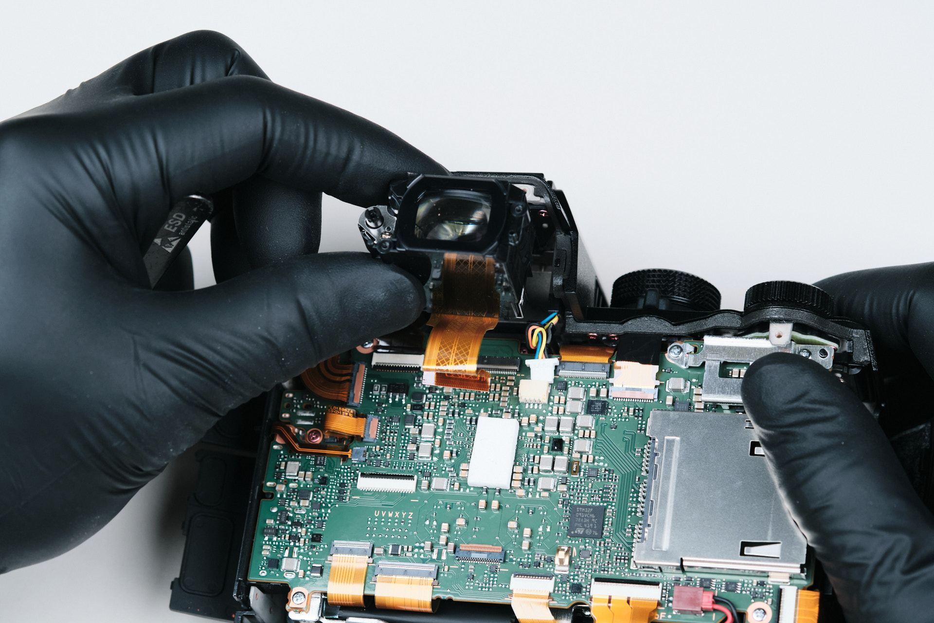
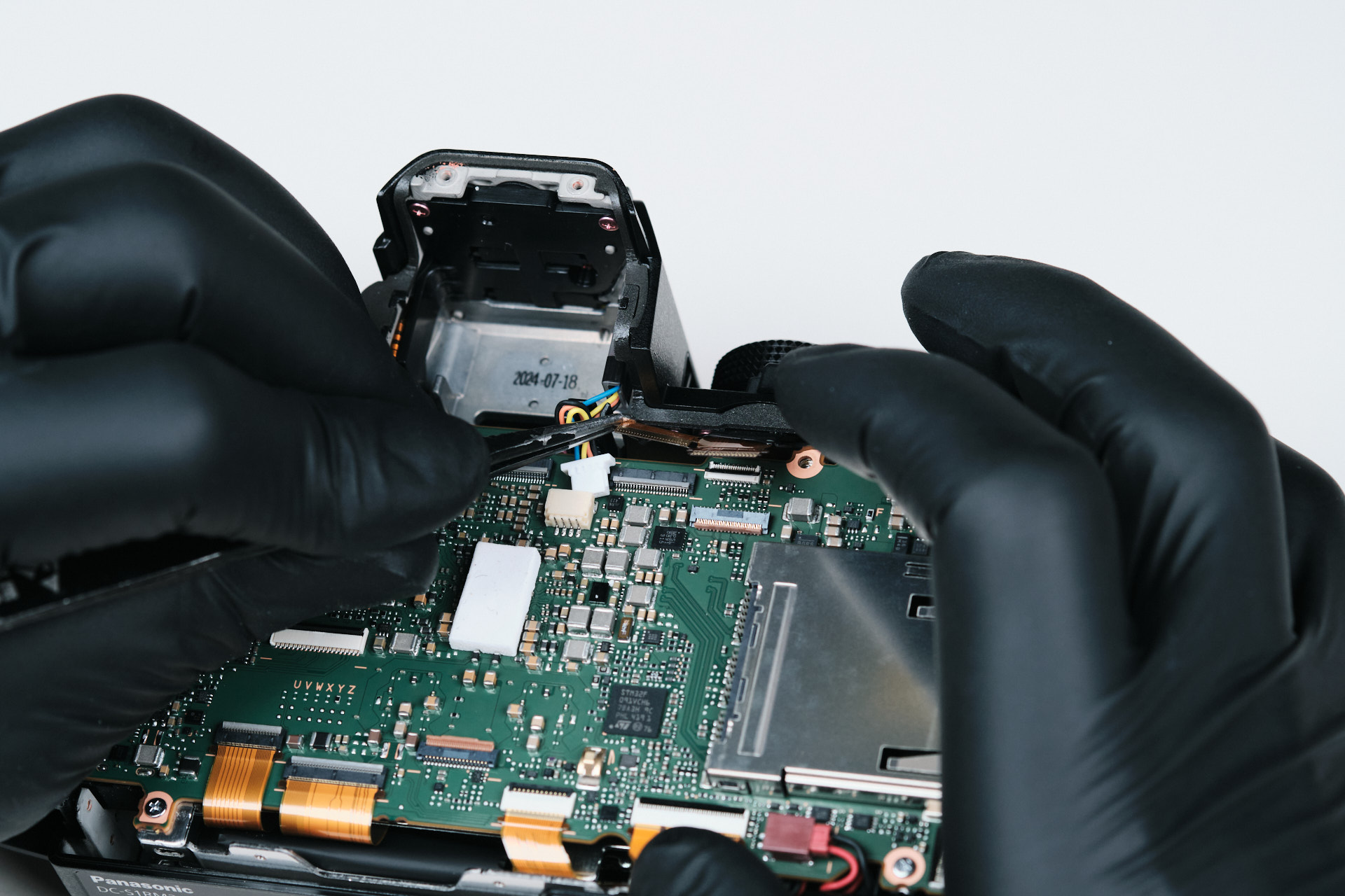
Moving on to the camera’s interior, we opted to remove the viewfinder. This piece was connected to the circuitboard via one ribbon cable. There’s also a wire that connects to the circuitboard—however, this wasn’t fastening the viewfinder to the circuitboard. Presumably, it is a wired connection that serves as supplemental data transfer between the camera dials and circuitboard.
The viewfinder itself.Â
Some camera teardowns become a matter of meandering around to get familiar with the design, and the S1R II is no exception to this. For the following few steps, we went back and forth between the circuitboard and front plate of the camera as we were trying to figure out how to remove parts.
Removing the Panasonic Lumix S1R II Circuit Board
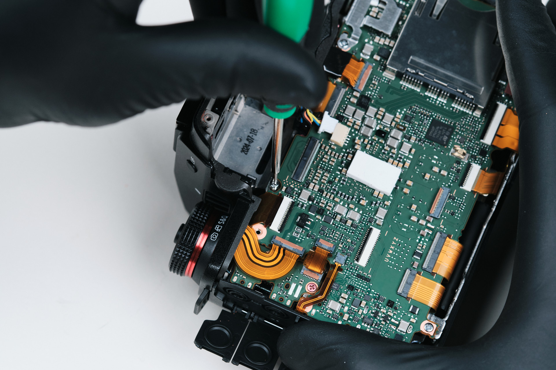
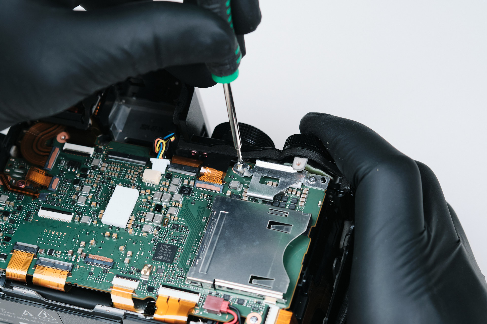
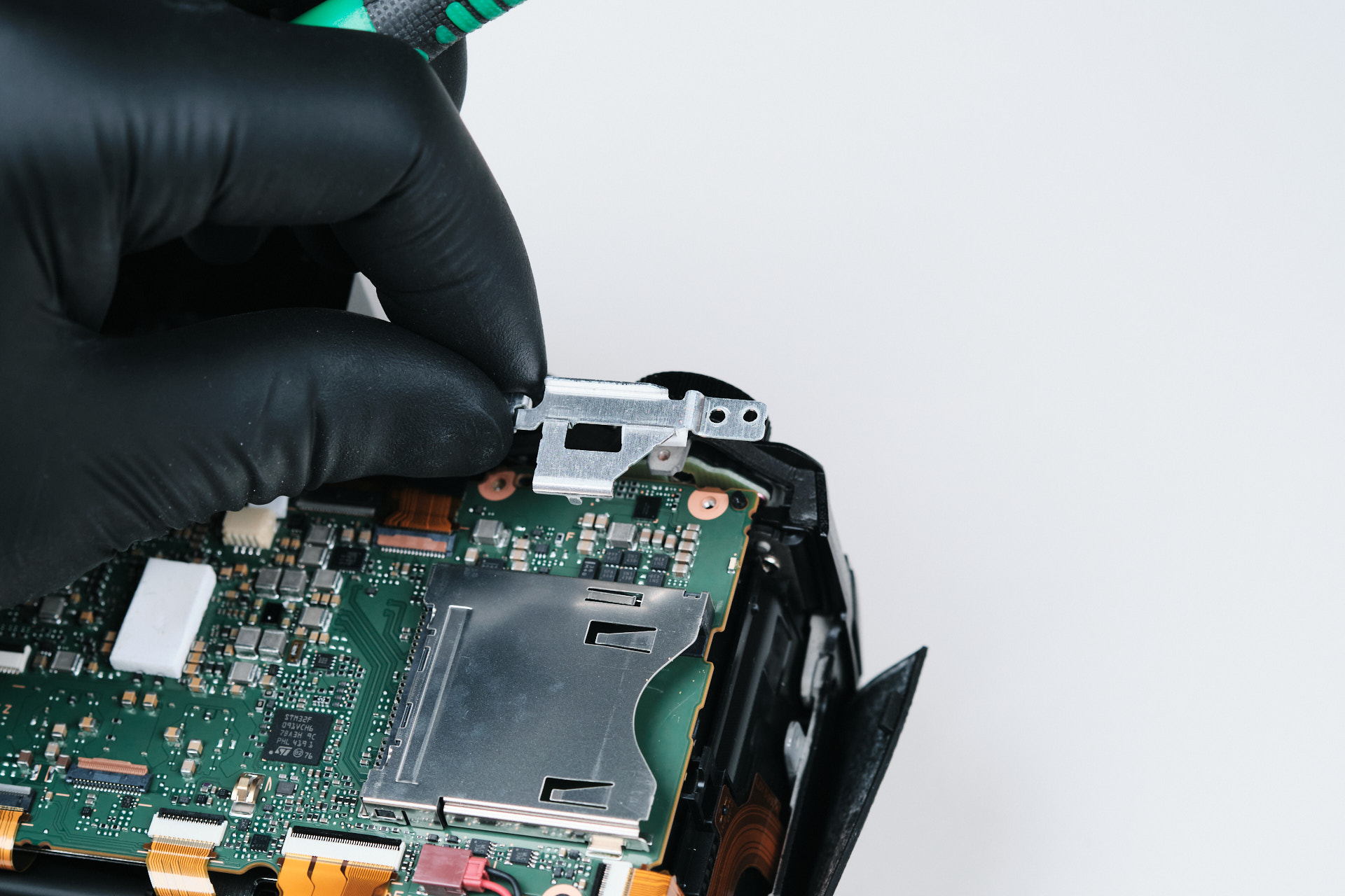
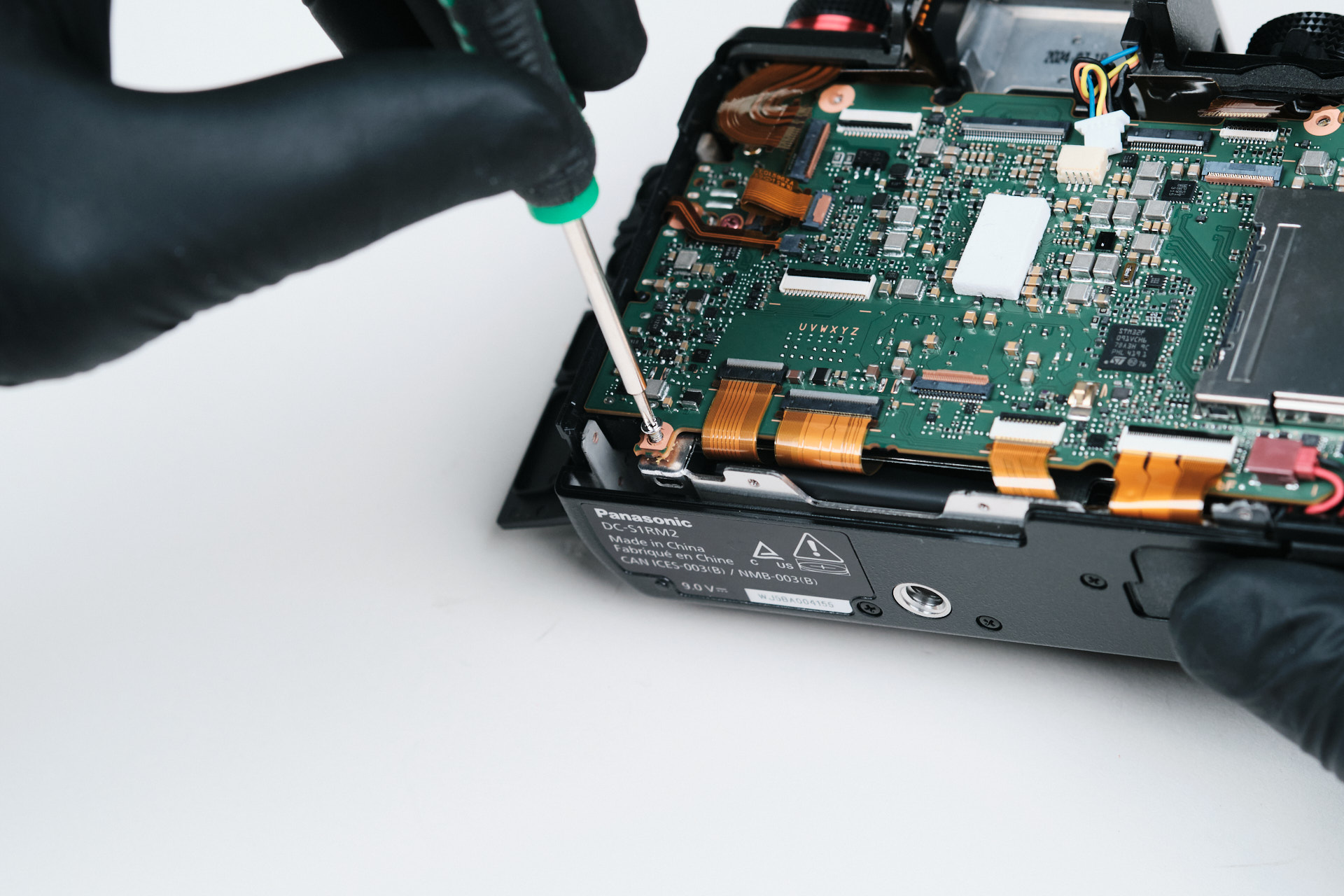
To start, this camera’s circuitboard didn’t come off as easily as we thought it would, which was due to the unorthodox design and layers of the camera. On the top right of the circuitboard, there was a mini bracket that we nearly missed while trying to removing the circuitboard. We also removed one screw form the circuitboard during this step, but we’ll be removing more screws later on.
Removing Additional Hidden Screws and PCB Connections
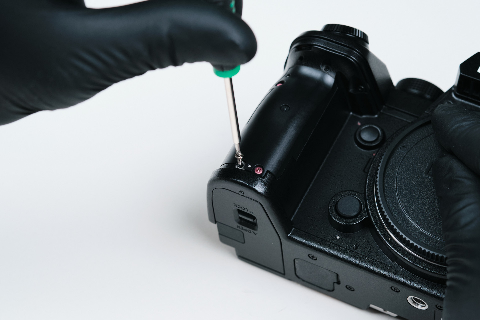
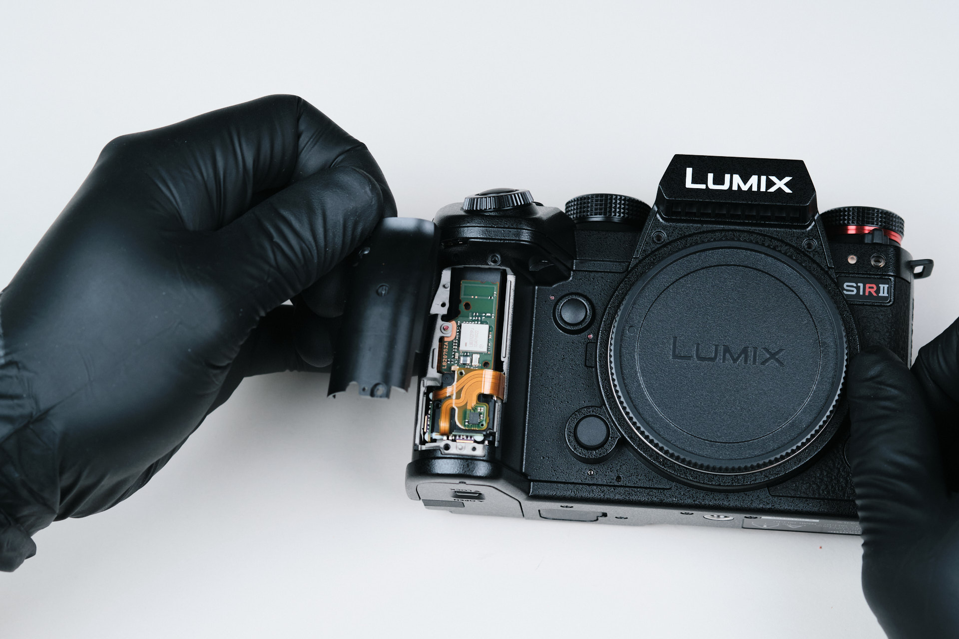
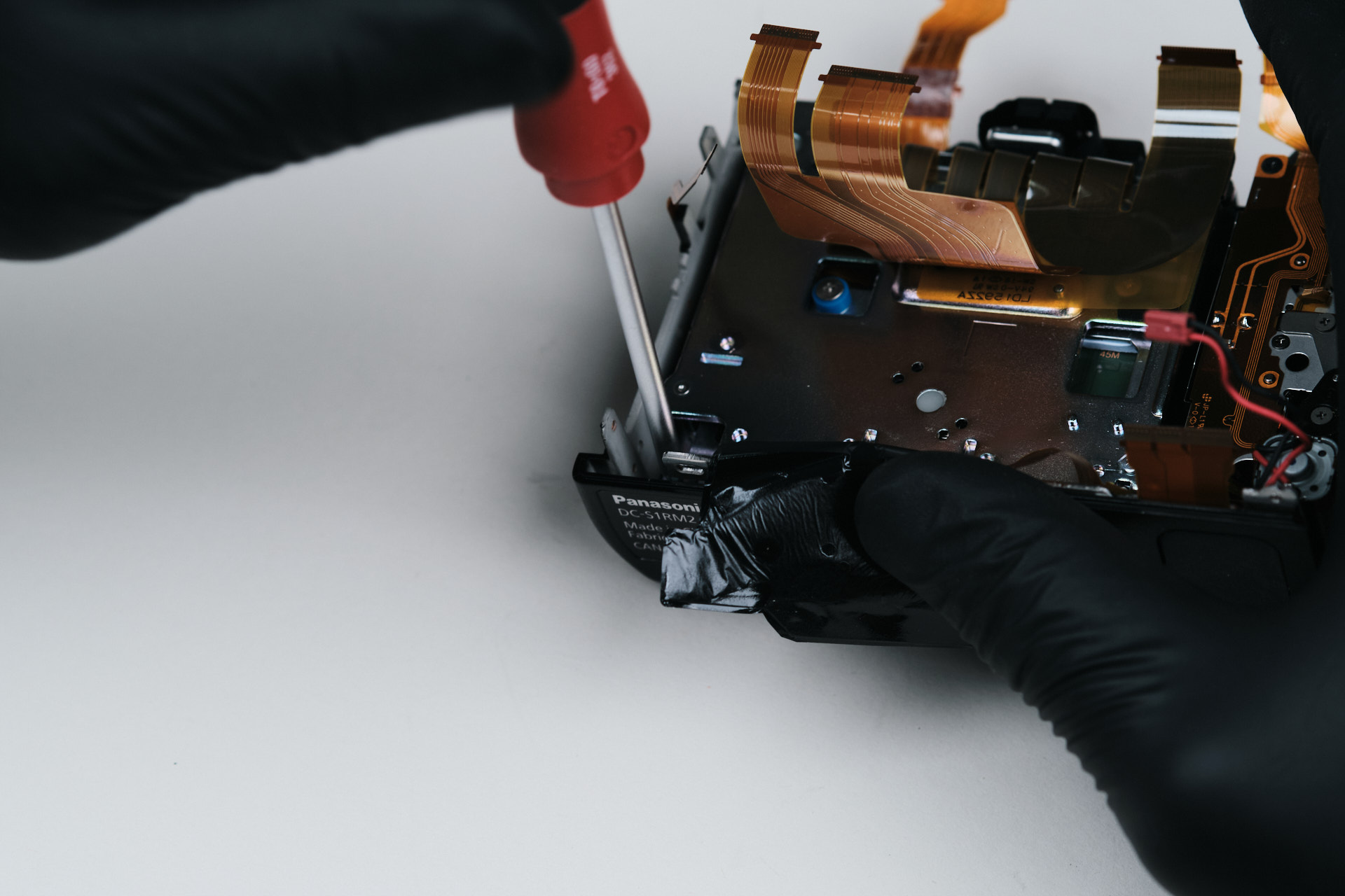
Moving on to the front of the camera, we removed more of the leather skin exterior to find more hidden screws. The handgrip side of the camera actually had an opening in the frame that housed a mini circuitboard. There was also a hidden screw on the underside of the handgrip.
The left side of the camera revealed a few more hidden screws.
Removing the Main Circuit Board
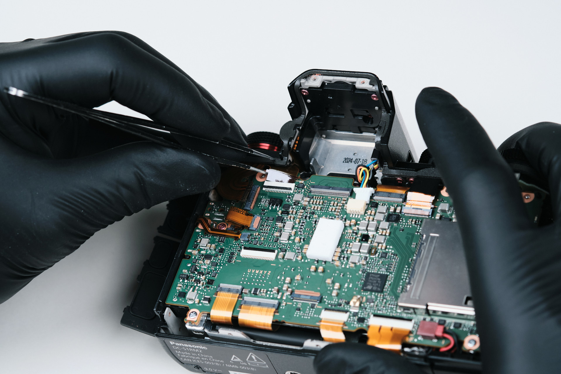
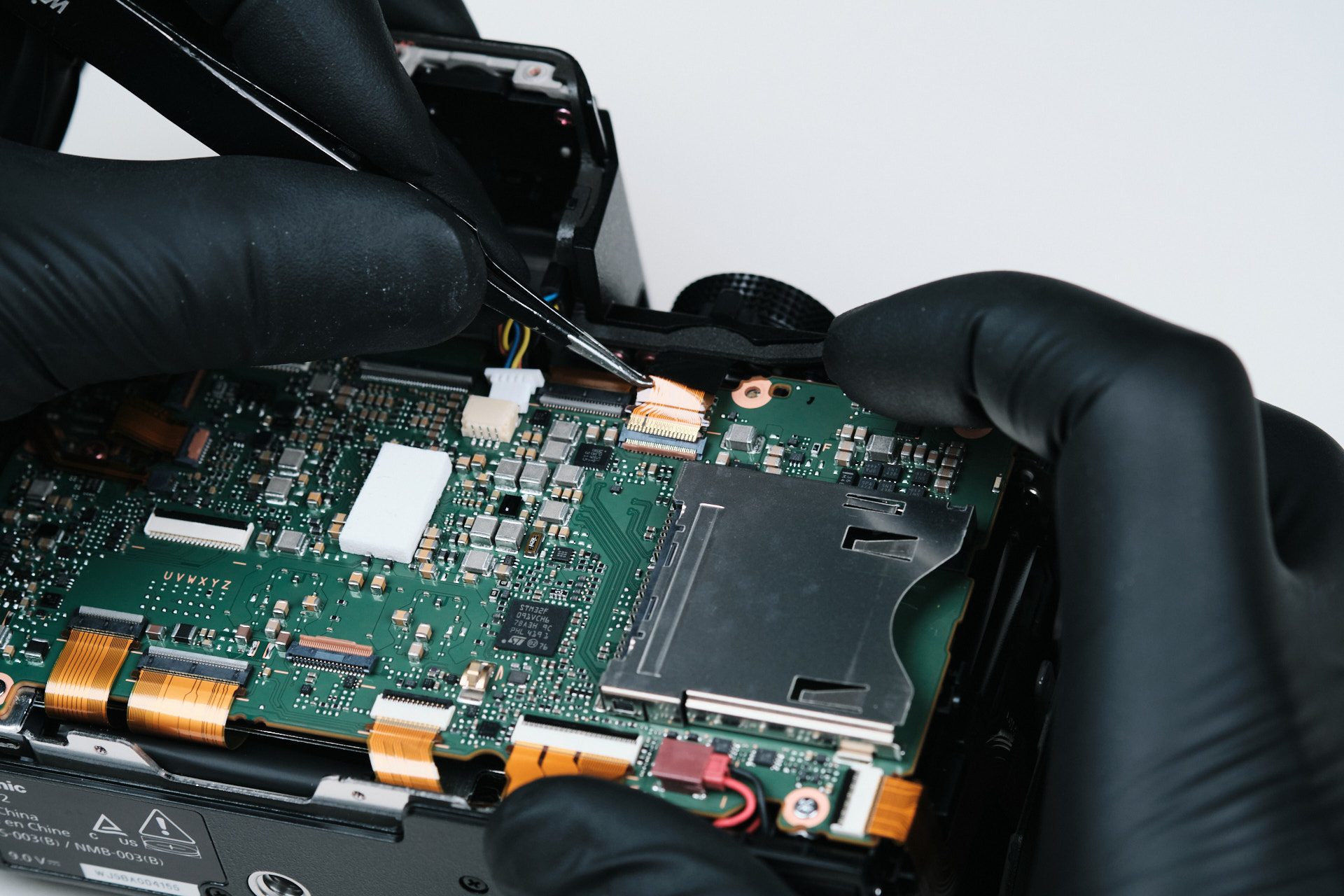
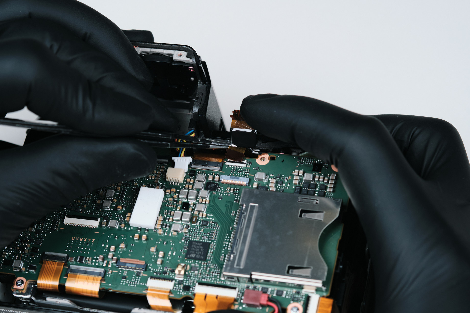
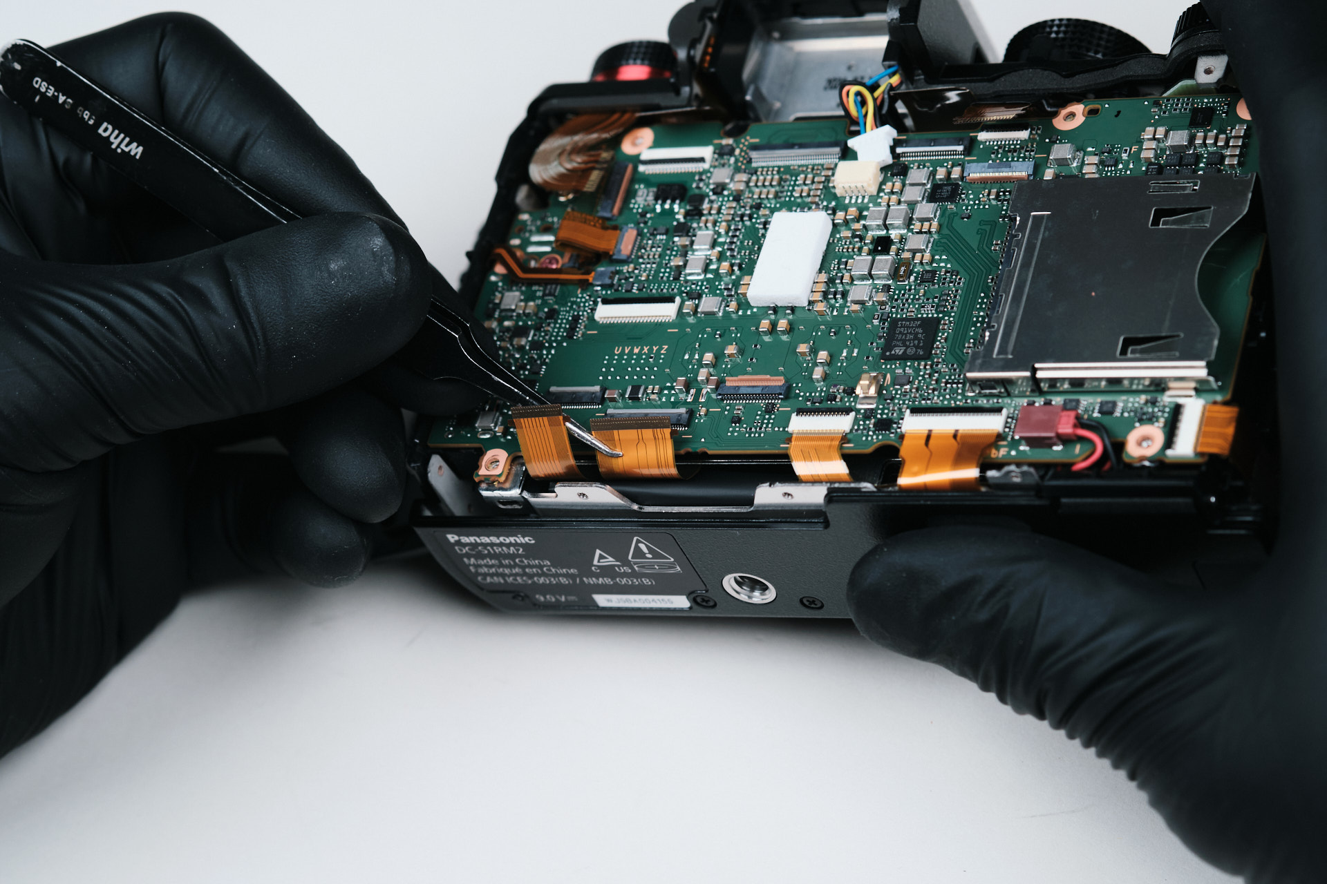
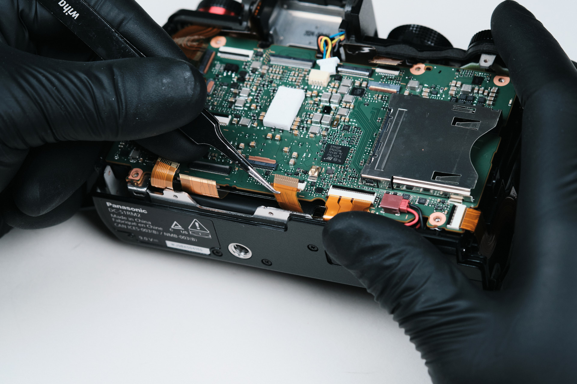
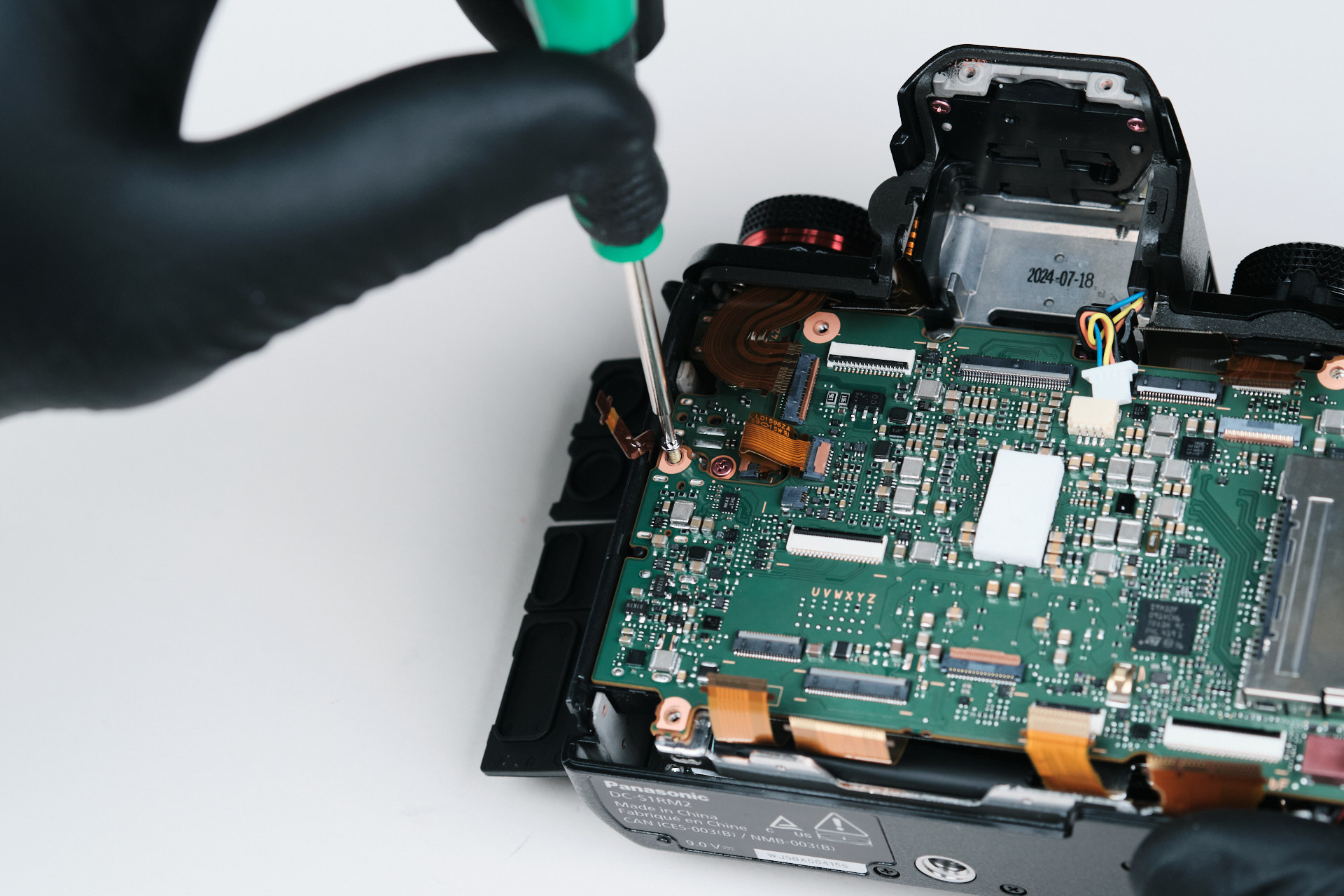
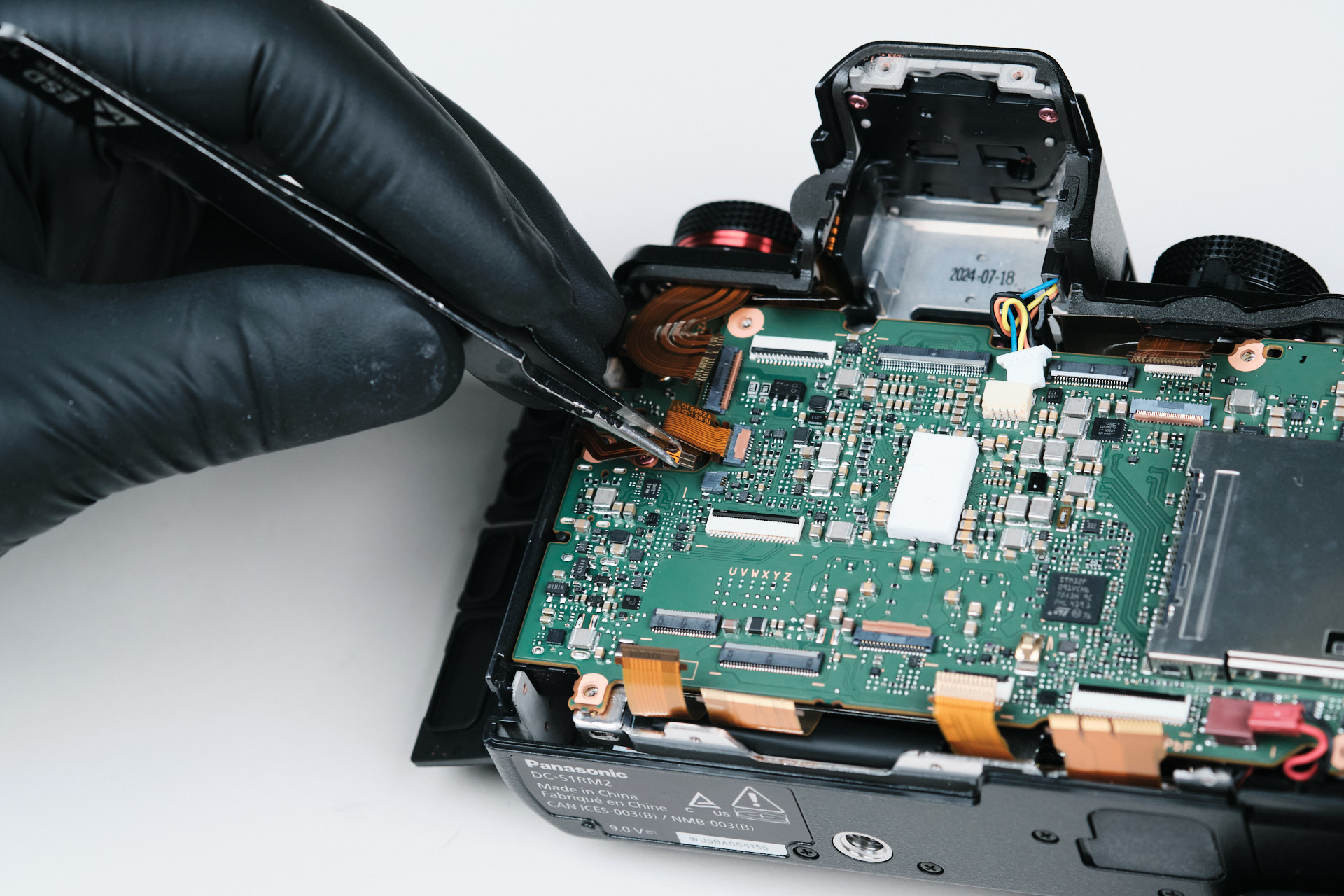
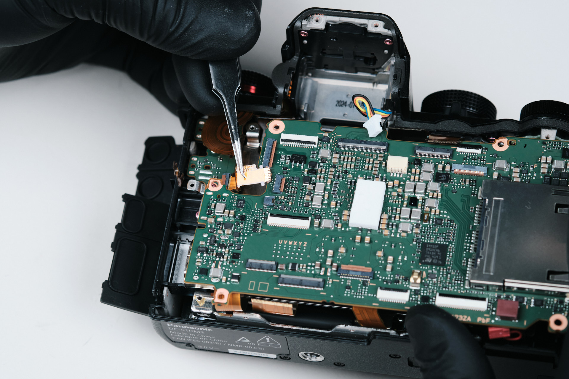
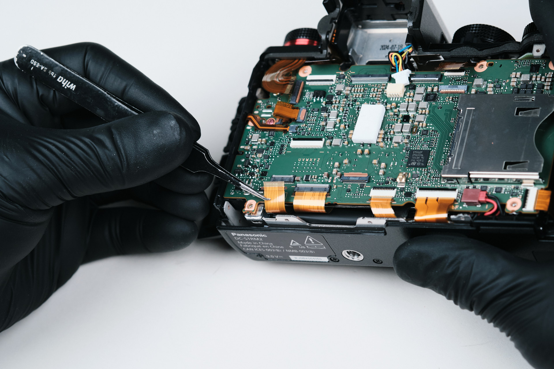
Now we’re back to the circuitboard again. The upper area of the PCB had five ribbon cable connections. Interestingly, one of the cables was hidden directly underneath another ribbon cable.
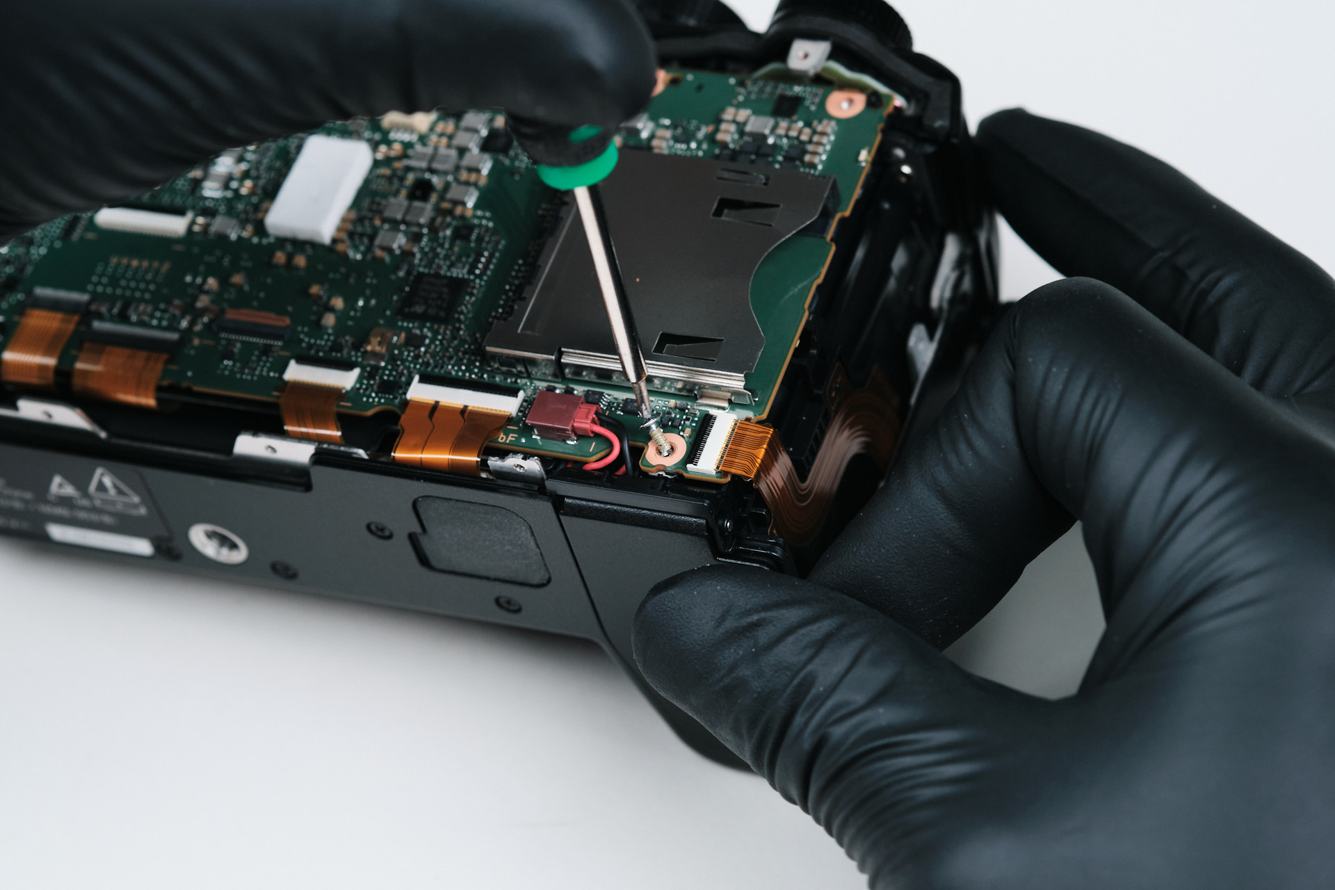
Here we removed two screws.
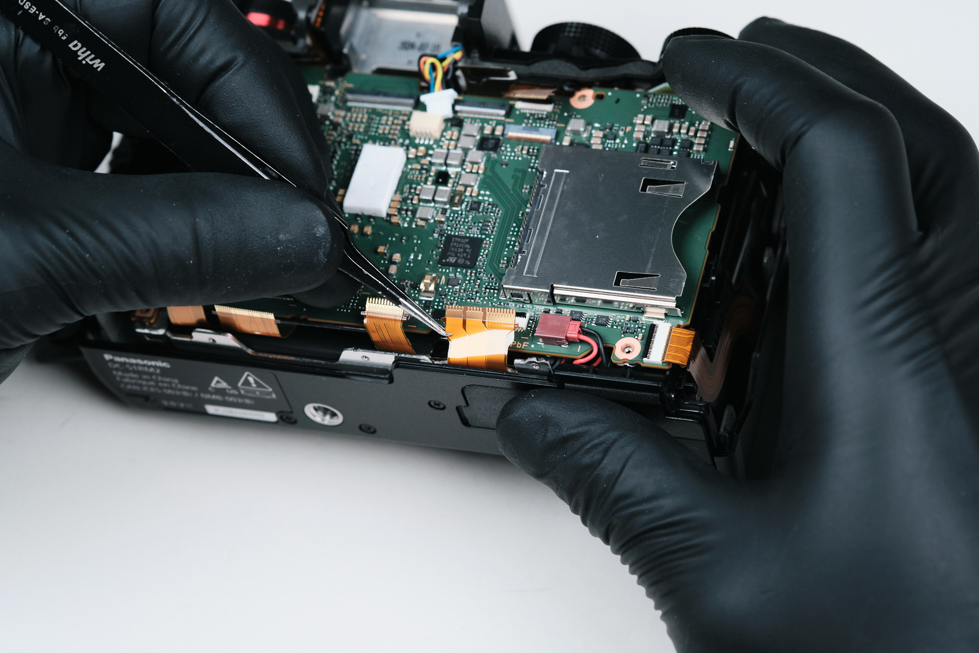
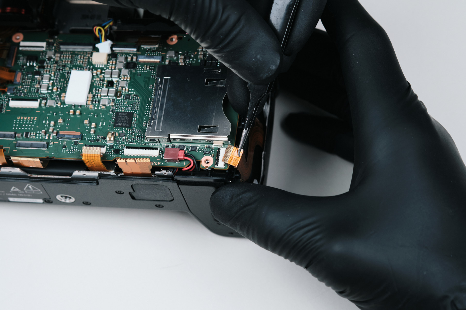
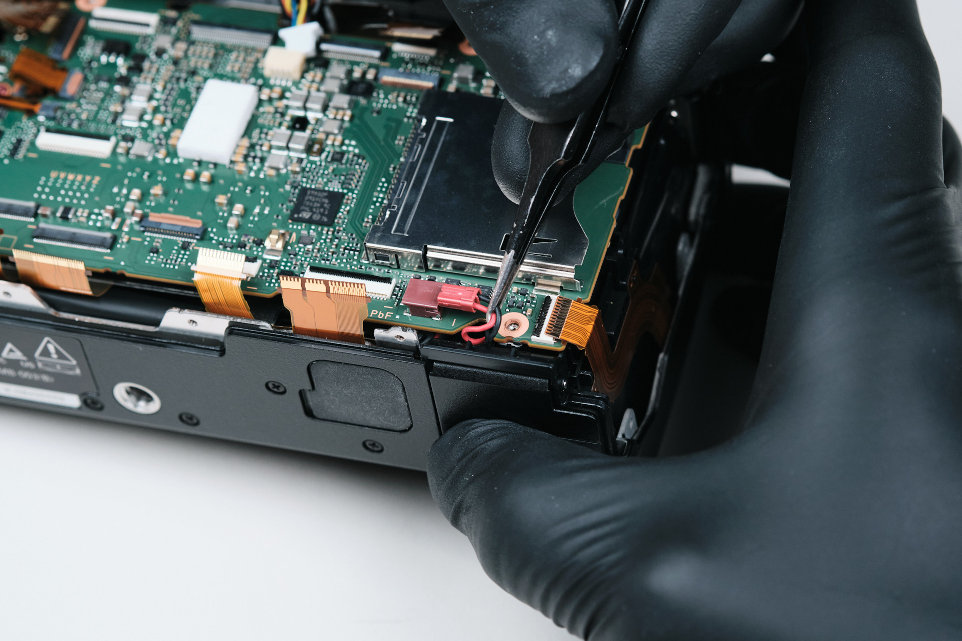
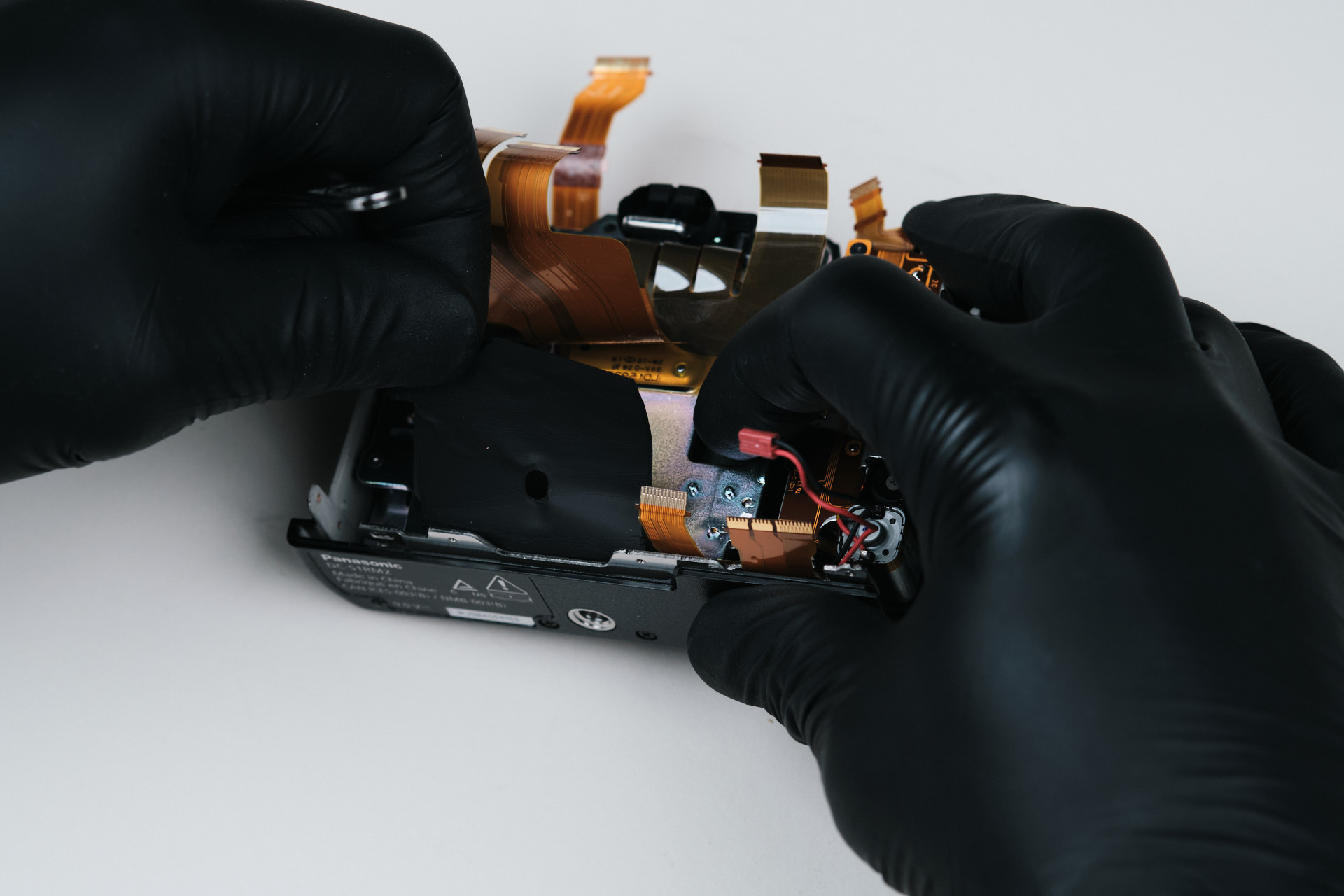
The lower half of the circuitboard had five ribbon cable connections and one wired connection.
Closer to the center of the circuitboard, there are three more connections which include two ribbon cables and one wire. Removing these connections finally allowed us to lift off the circuitboard.
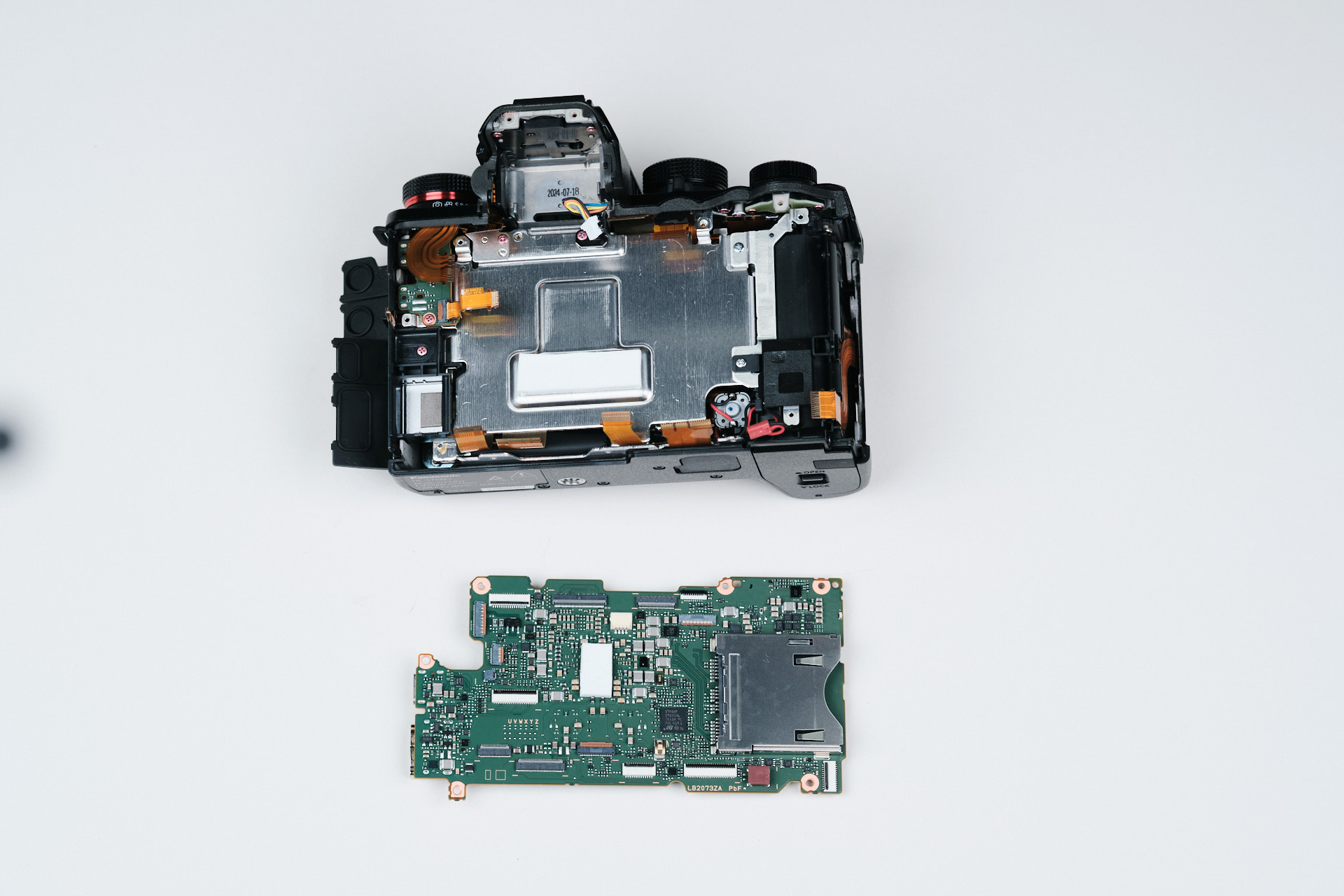
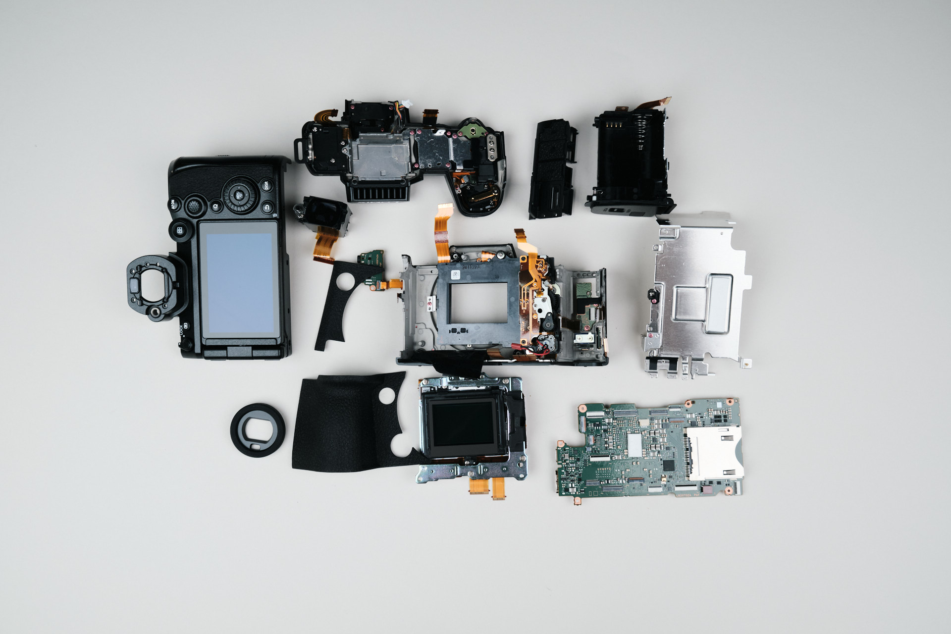
Here is the circuitboard removed from the camera body frame.
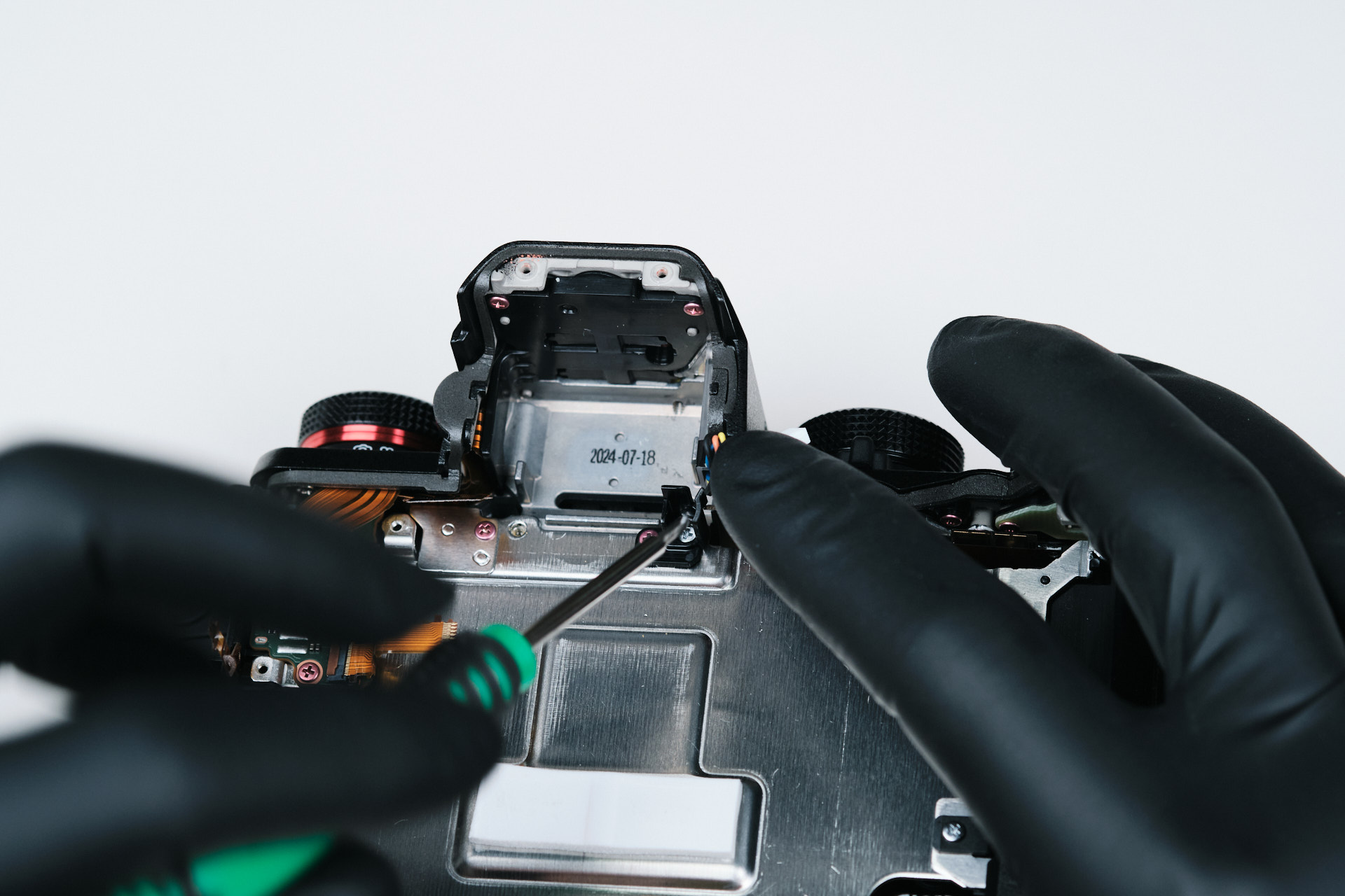
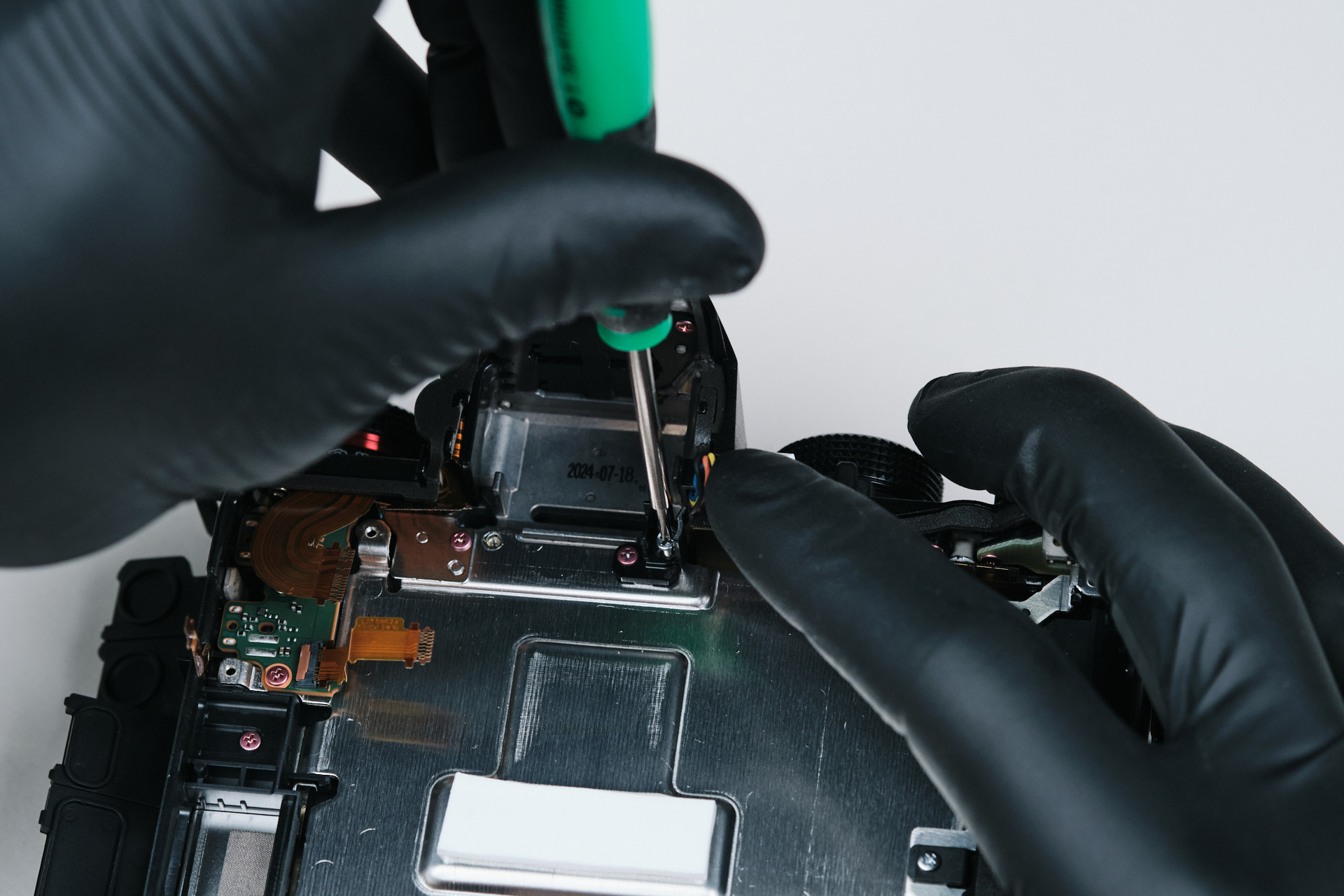
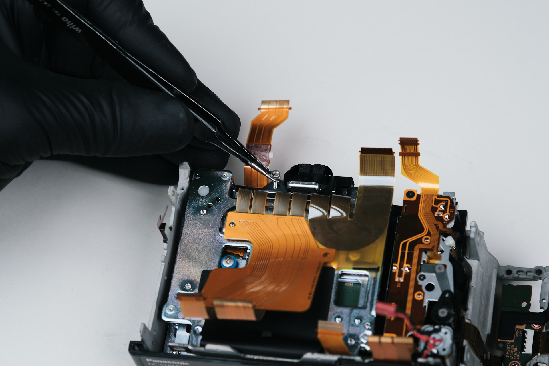
One more screw held the top part of the camera.
Removing the Sensor Bracket and Battery Compartment
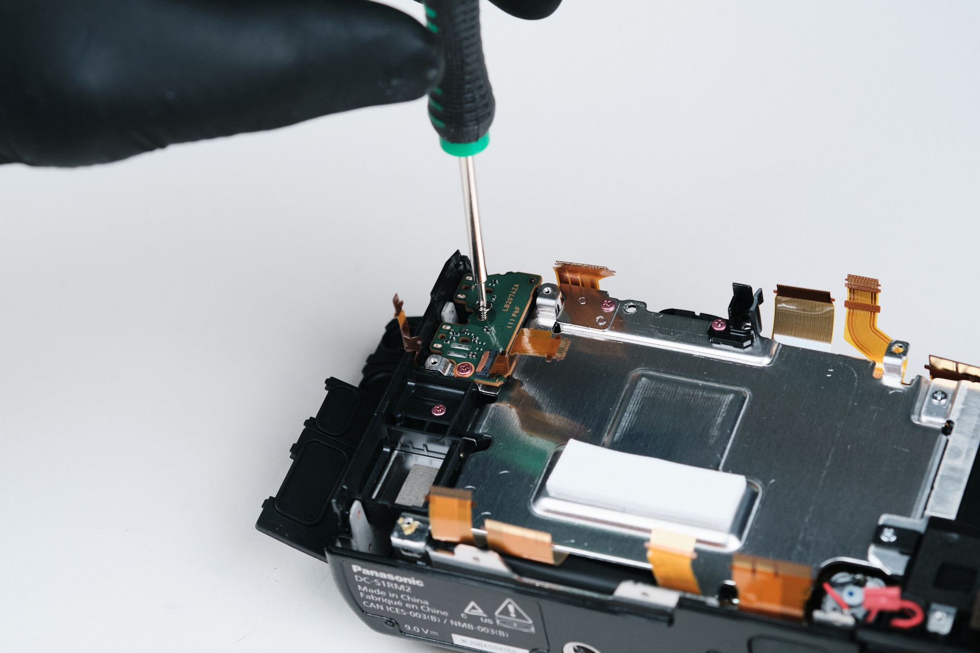
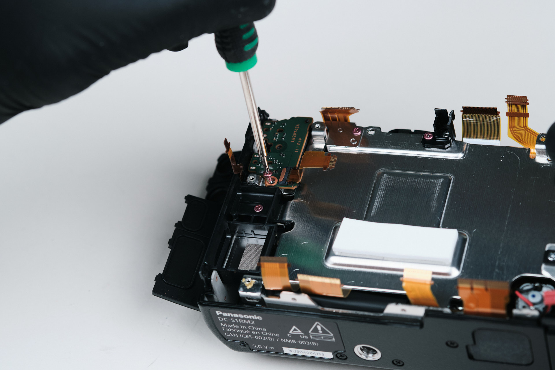
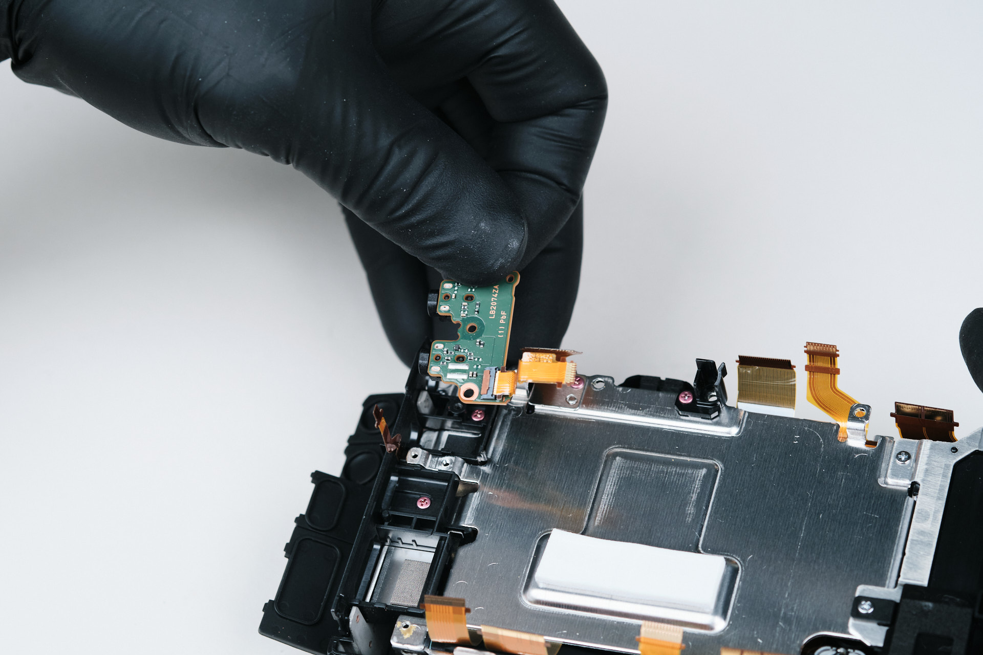
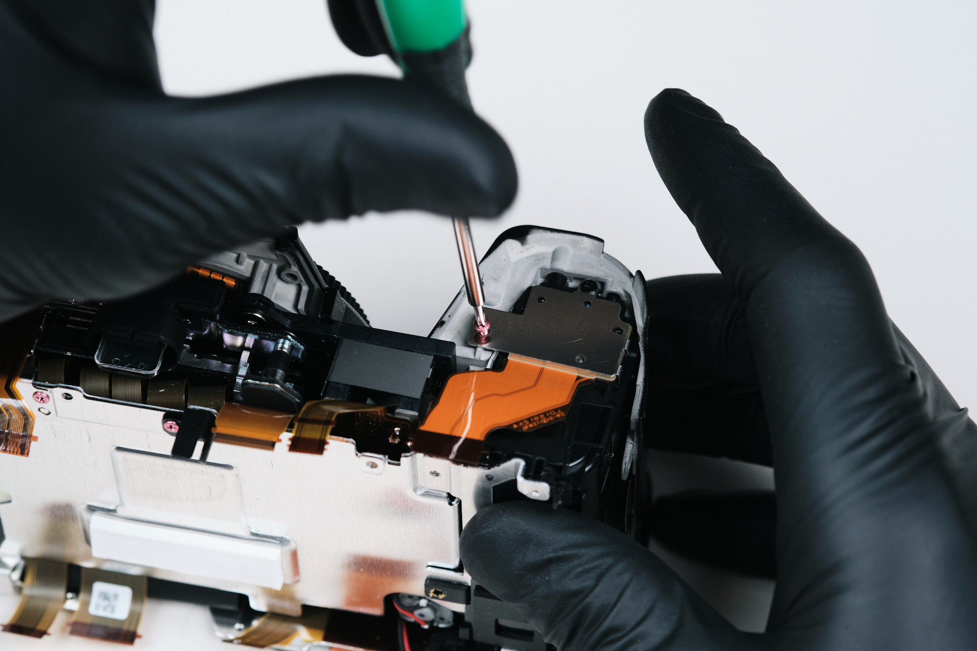
Generally at this stage, we start to remove the camera sensor bracket. However, we noticed that there is a small PCB part in the upper left corner of the camera.
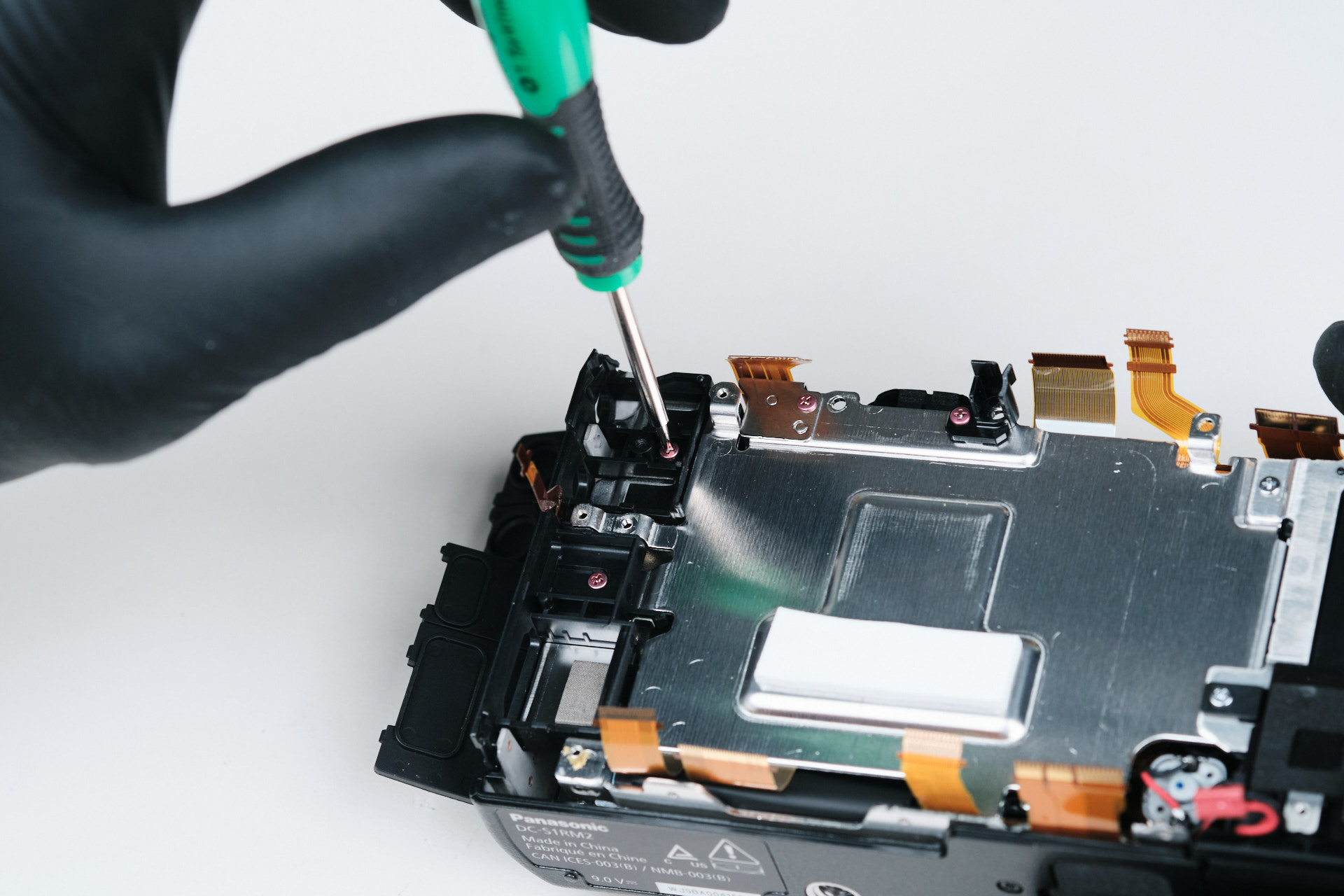
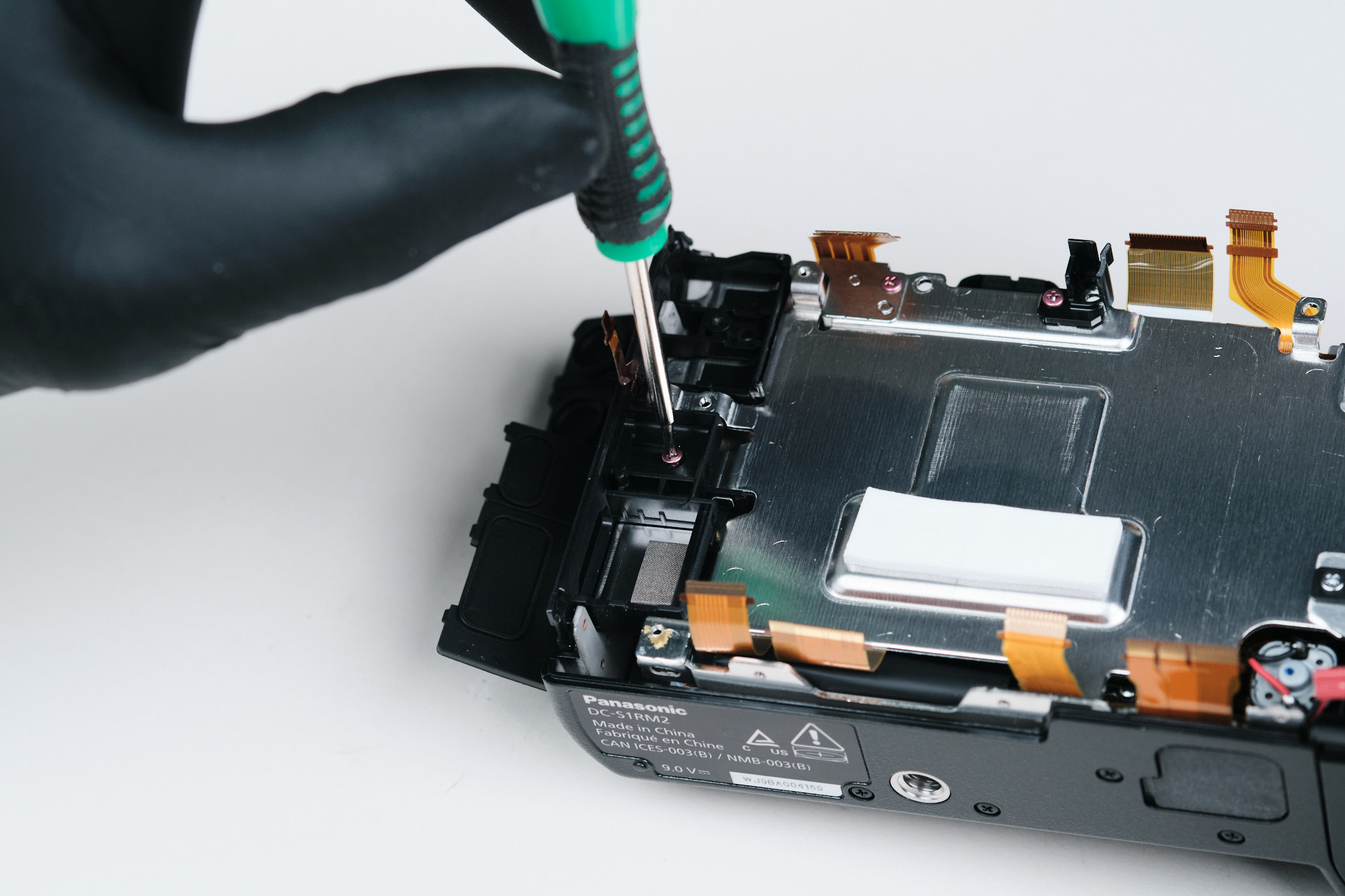
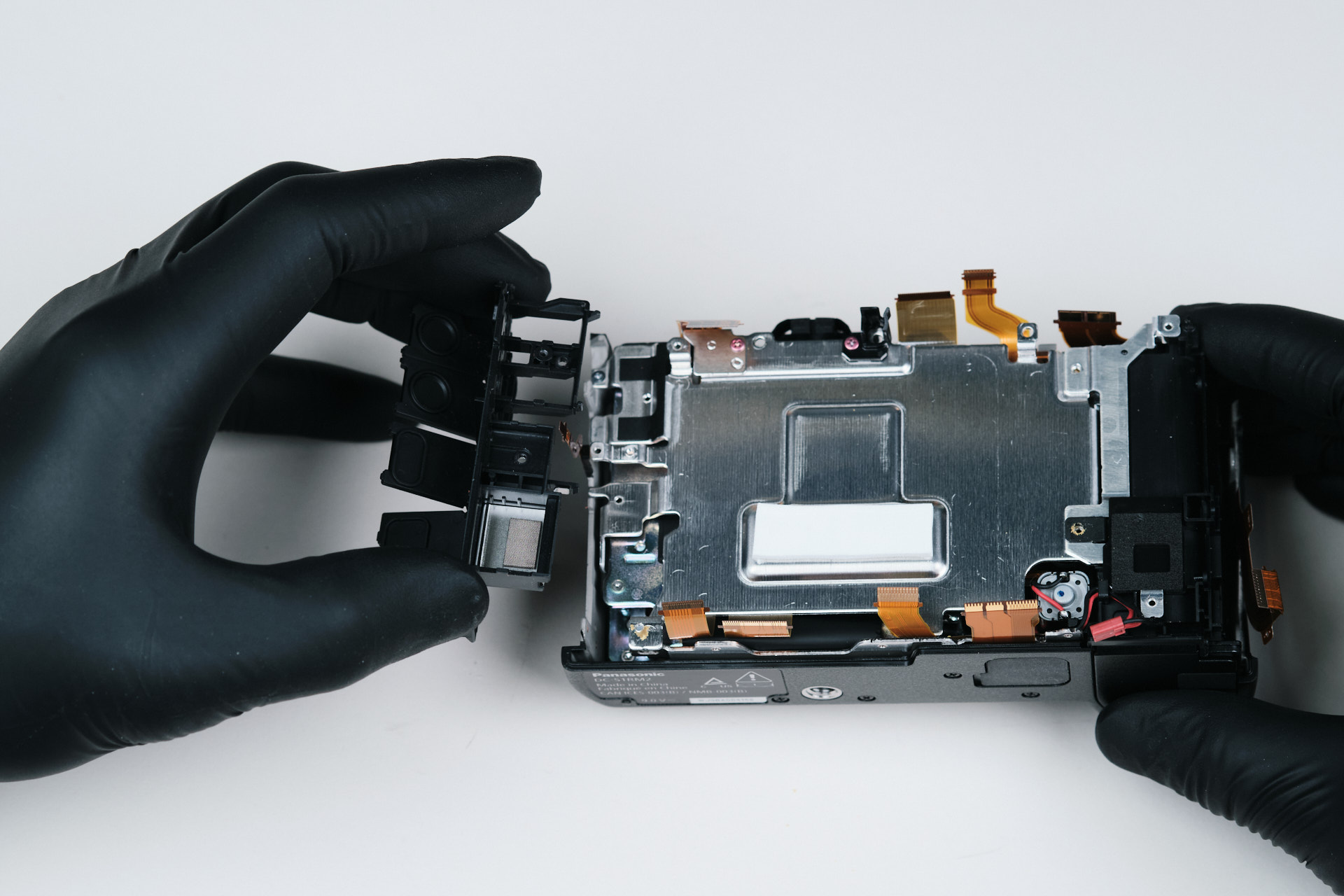
Further inspection revealed that the port side cover also doubles as an internal bracket. Usually, the port cover is a piece that can be pried from the outside once the screws are removed from the exterior.
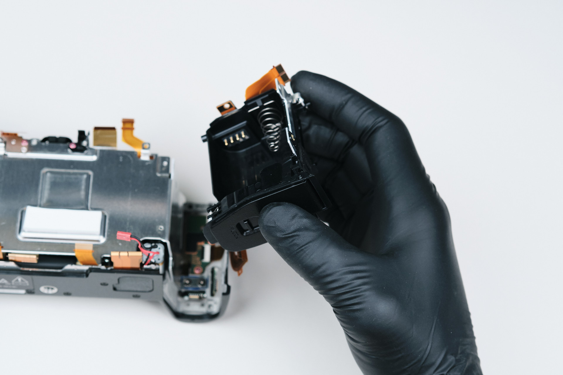
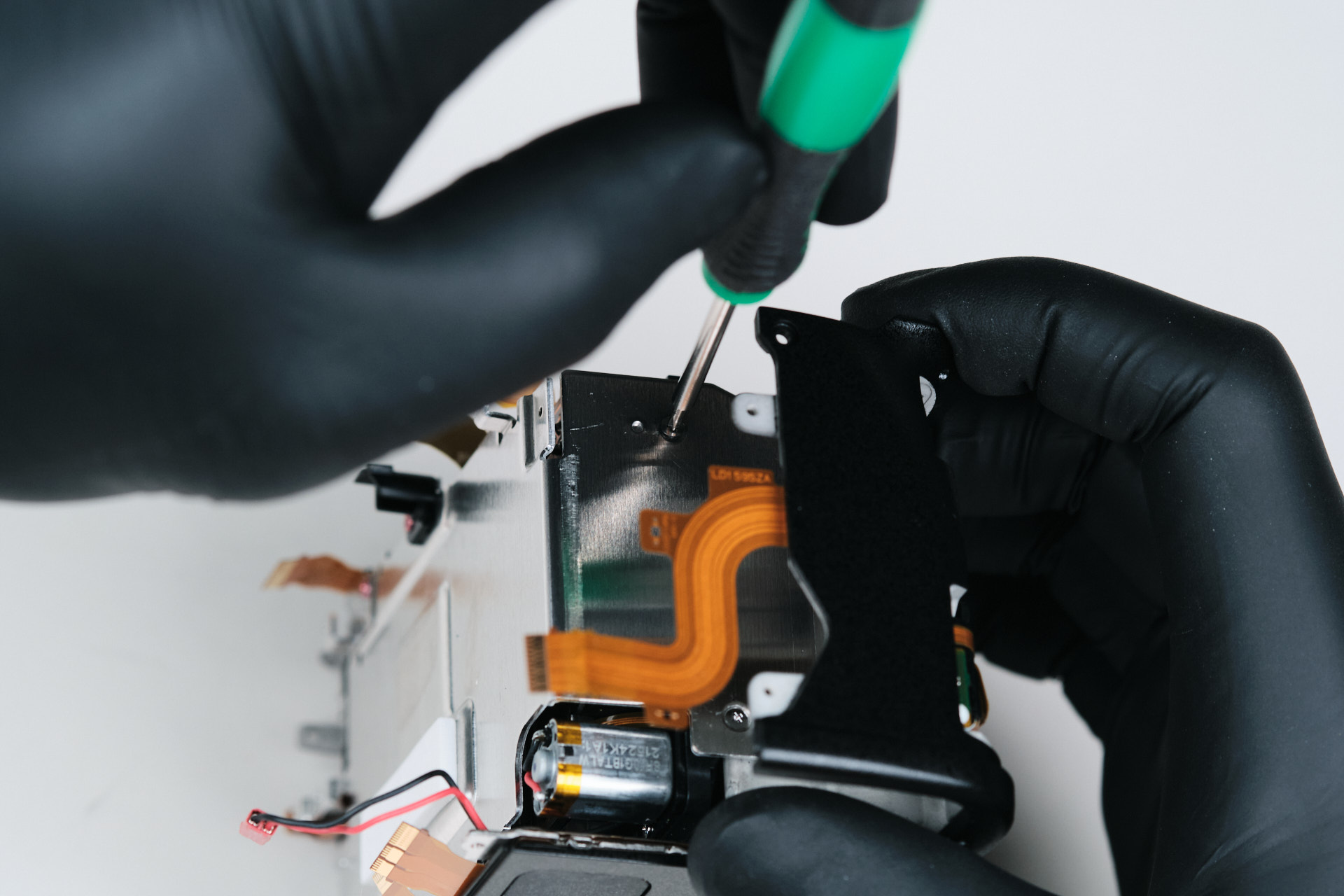
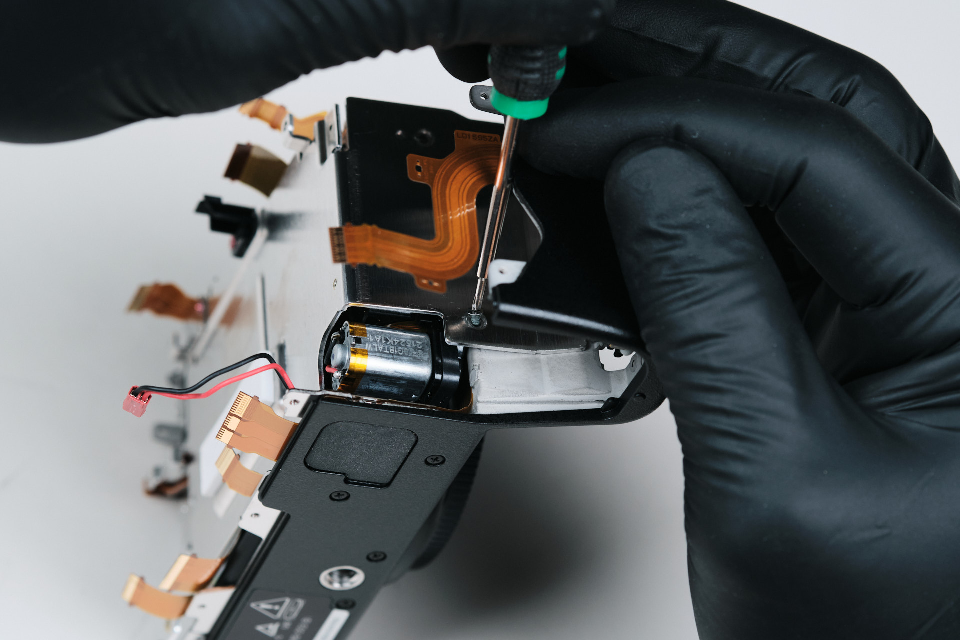
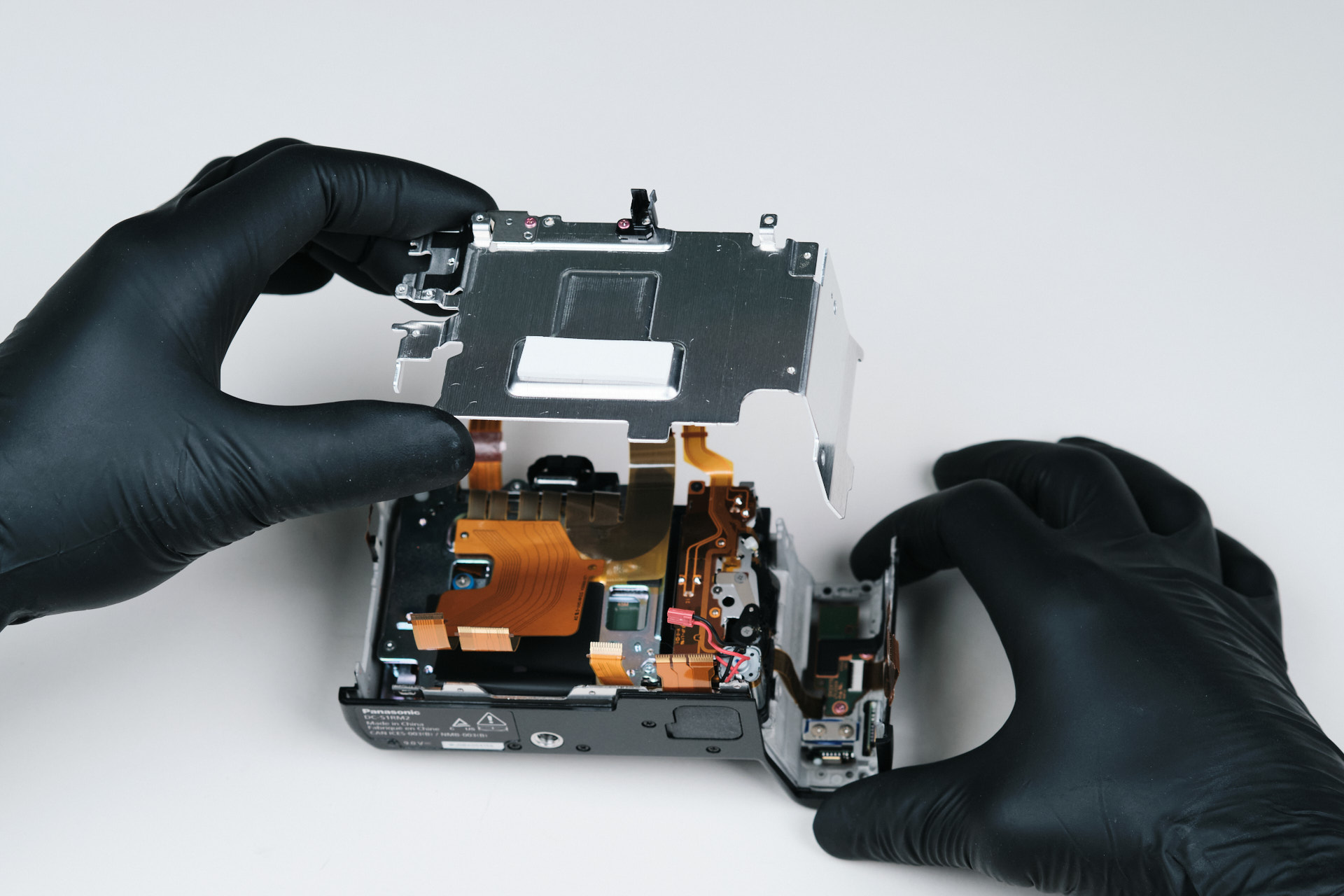
There was one screw on the top side of the internals, which held down the battery compartment. Battery compartments are usually built-in to the housing of the camera’s body, but the S1R II has a dedicated and removable battery compartment piece. Removing that exposed two screws for the main camera sensor bracket.
Removing the Panasonic Lumix S1R II Camera Sensor
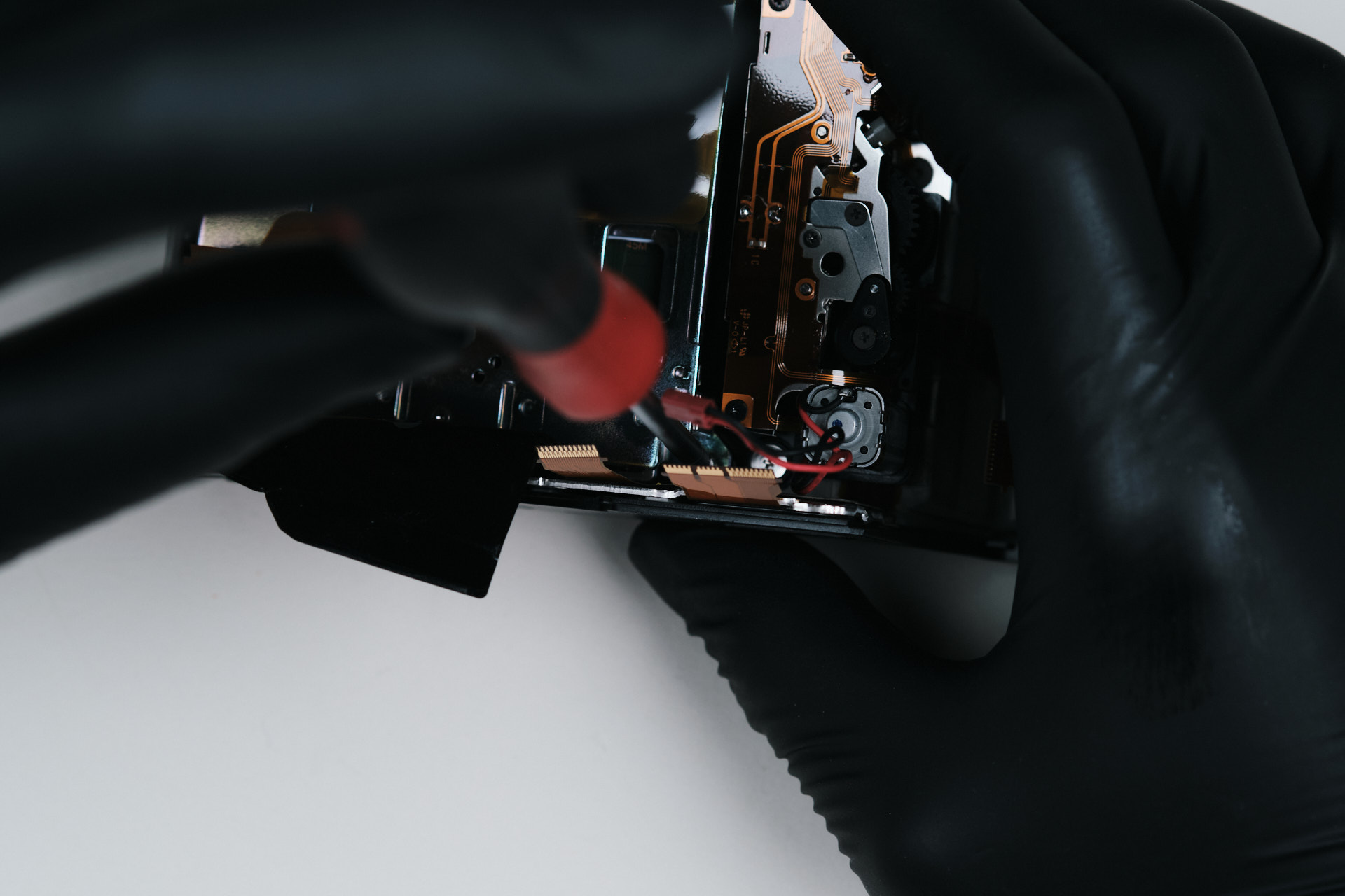
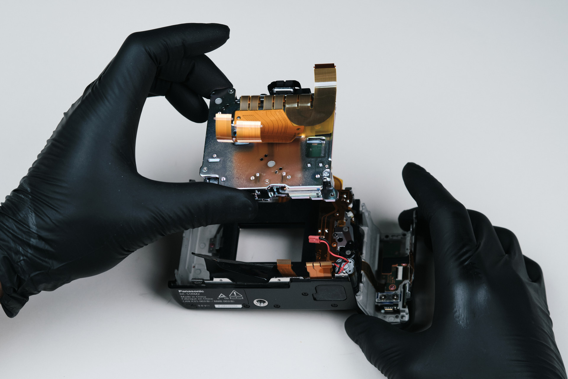
Removing the aforementioned screws allowed us to remove the main bracket. Now we can remove the camera sensor.
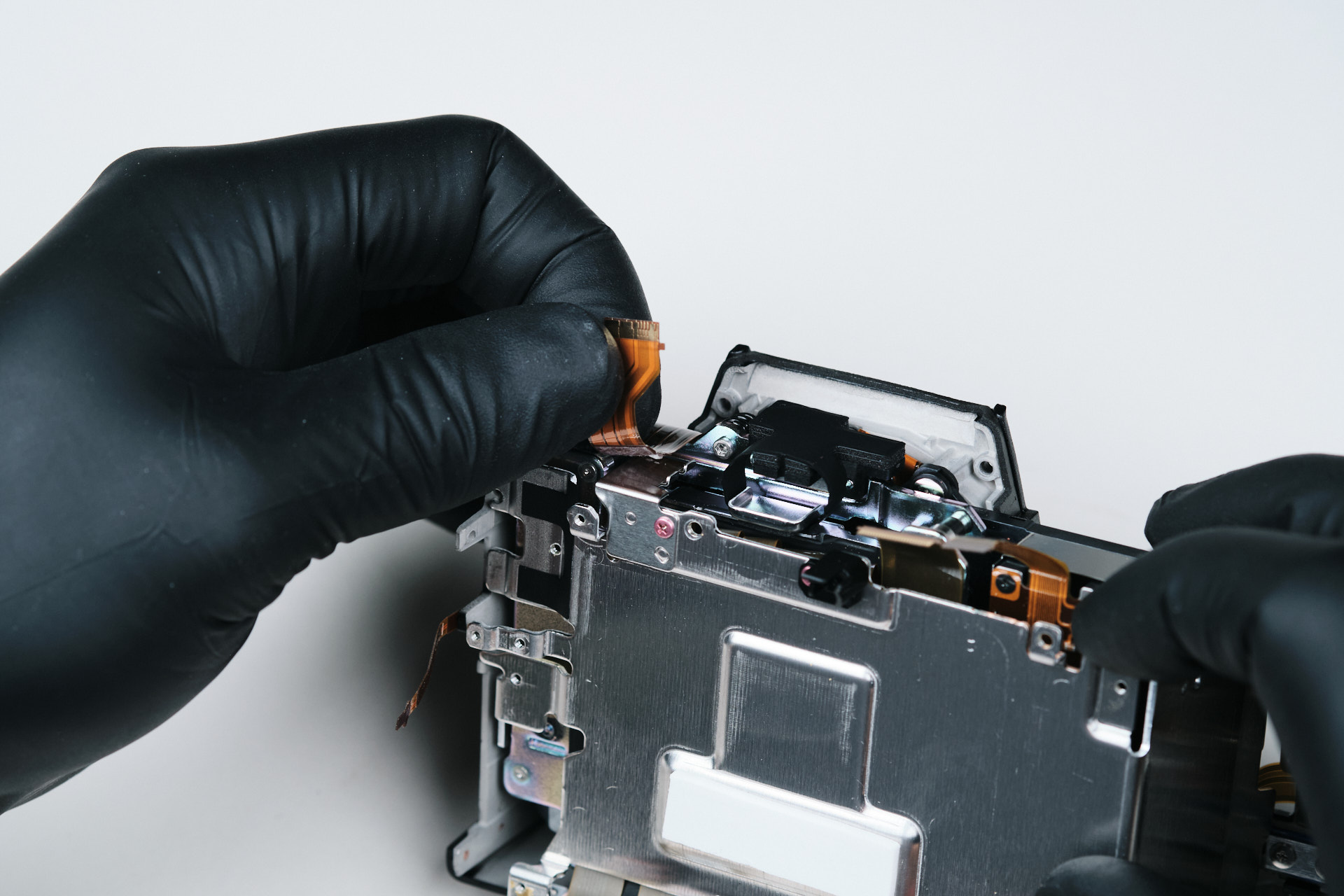
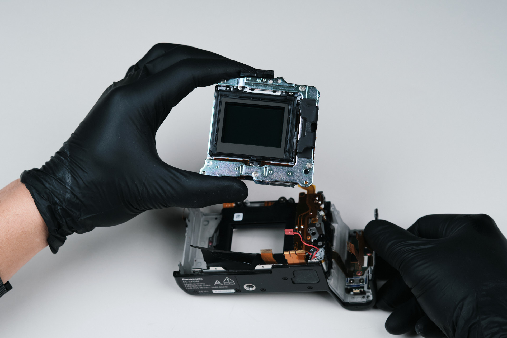
With the main sensor bracket removed, we had clear access to the Panasonic Lumix S1R II sensor assembly. From here, the sensor removal was much more straightforward.
Once the surrounding screws and ribbon cable were disconnected, the sensor came out cleanly. This final step was simpler than the earlier exterior disassembly.
Panasonic Lumix S1R II Infrared Conversion Difficulty
According to our lead camera technician, the Panasonic Lumix S1R II is a DIY-friendly camera for infrared conversion. It’s similar to the Canon EOS R5 in terms of difficulty levels, meaning not difficult at all.
Â
Thanks for reading. If you’re interested in more camera teardowns, we feature a new one every month. Be sure to sign up for our newsletter so you don’t miss them!
Frequently Asked Questions
How Do You Start Disassembling The Panasonic Lumix S1R II?
The Panasonic Lumix S1R II disassembly starts by inspecting the bottom of the camera. Unlike many cameras, the S1R II does not have a dedicated baseplate piece, so the teardown begins by removing screws from the bottom of the rear backplate.
Where Are The Hidden Screws On The Panasonic Lumix S1R II?
Several hidden screws are located underneath the exterior leather skin. The teardown found hidden screws near the joystick, on the memory card side, on the handgrip side, and inside the diopter screw area.
How Is The Panasonic Lumix S1R II Rear Backplate Removed?
The rear backplate can be removed after taking out the visible exterior screws, hidden screws under the leather skin, screws near the viewfinder, and the hidden screw inside the diopter area. Two ribbon cables connect the rear backplate to the circuit board, so they need to be handled carefully.
How Is The Panasonic Lumix S1R II Circuit Board Removed?
The circuit board is removed after disconnecting multiple ribbon cables and wired connections. The upper PCB area has several ribbon cable connections, including one hidden under another ribbon cable, while the lower half also includes multiple ribbon and wire connections.
Is The Panasonic Lumix S1R II Good For Infrared Conversion?
According to the teardown, the Panasonic Lumix S1R II is considered DIY-friendly for infrared conversion. The article compares its difficulty level to the Canon EOS R5, meaning it is not especially difficult for an experienced technician.