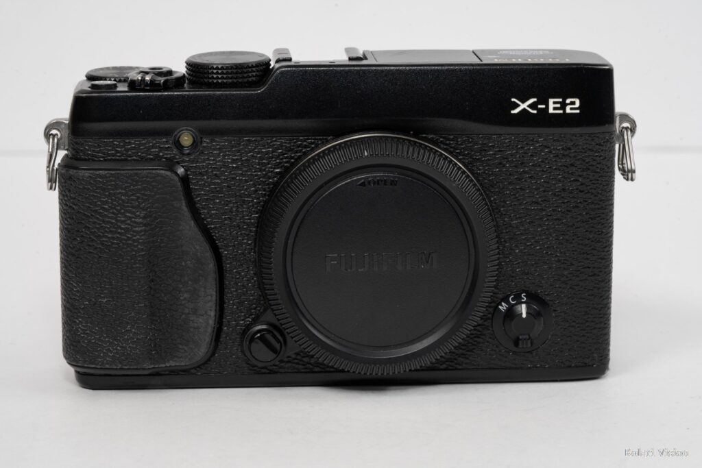
Use this guide to replace the top casing on your Fuji X-E2.
1
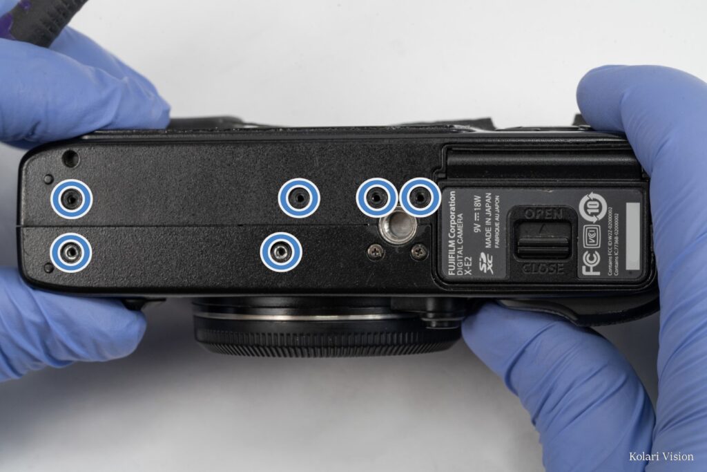
Step 1
On the bottom of the camera, remove the upper 4 screws and the lower 2 left screws.
2
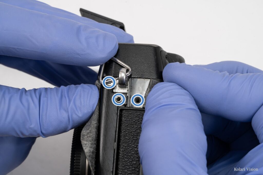
Step 2
On the left-side, peel back the leathers at the top, revealing 3 screws at the strap-ring mount. Remove all 3.
3
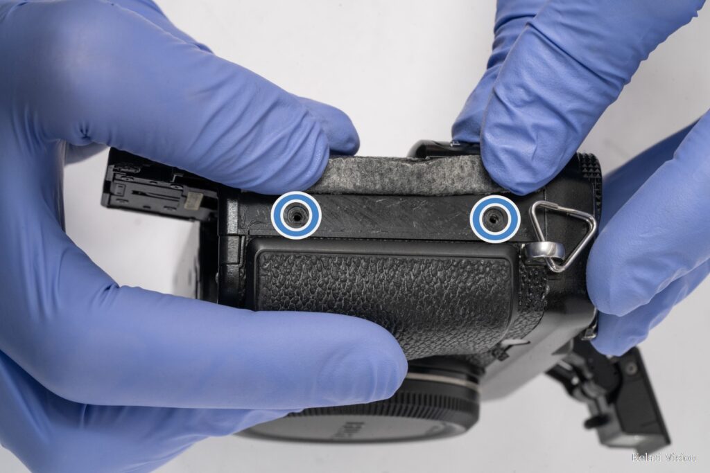
Step 3
Peel back the leathers on the right-side and remove the 2 screws at the top and bottom.
4
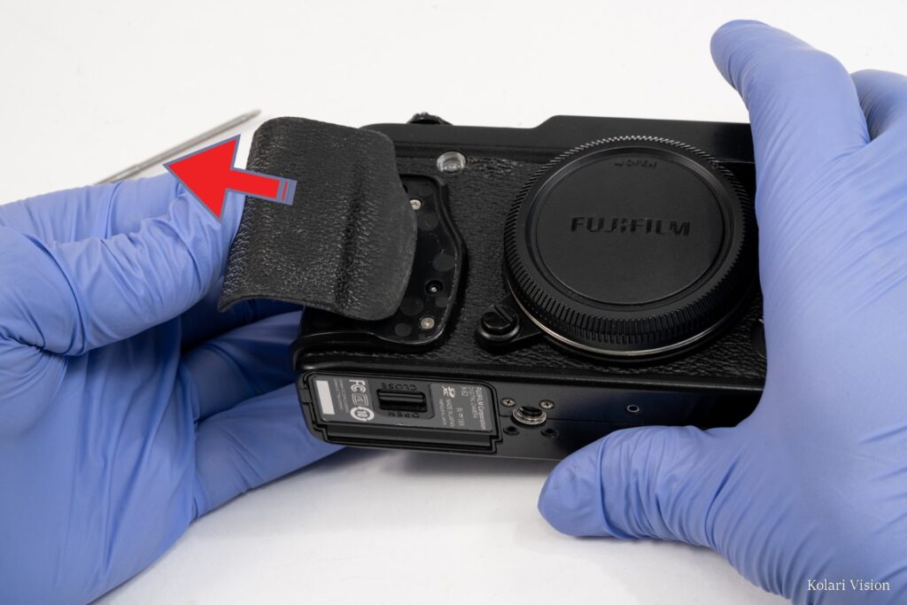
Step 4
Peel off the rubber over the handgrip.
5
Step 5
Remove the 4 screws affixing the plastic grip-base and take it off.
6
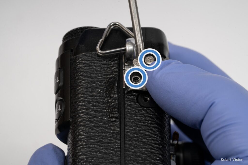
Step 6
Removing the hand grip will reveal a screw on the left side, just below the strap-ring mount. Remove that screw and the one above it.
7
Step 7
On the front, peel back the leathers at the top, revealing a total of 3 screws. 1 around the focus assist light and 2 near the X-E2 icon.
8
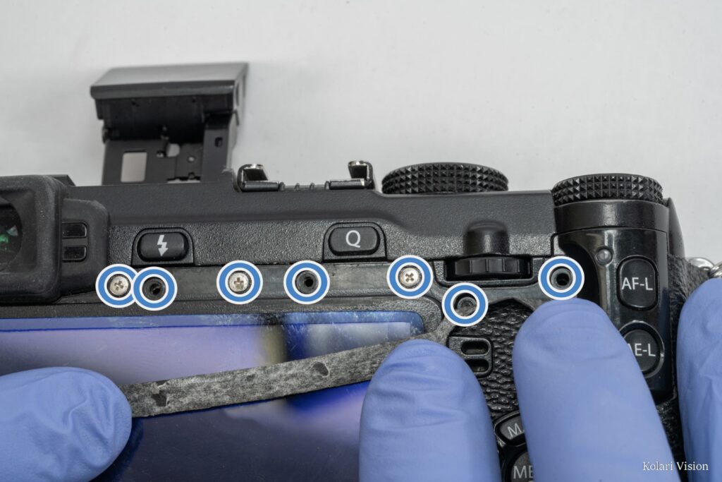
Step 8
On the back, peel back the leather along the top, revealing 7 screws to remove.
9
Step 9
Separate the back casing from the camera body, but do not completely pull it off yet, there are still ribbons connecting it. Lift it from the left-side first.
As you pull the back cover separate, you’ll notice a screw on the left side next to the strap mount, which can now be removed.
10
Step 10
Lift the back cover up from the left-side, keeping the right-side down. Disconnect the white and blue ribbon connecting the cover to the motherboard.
11
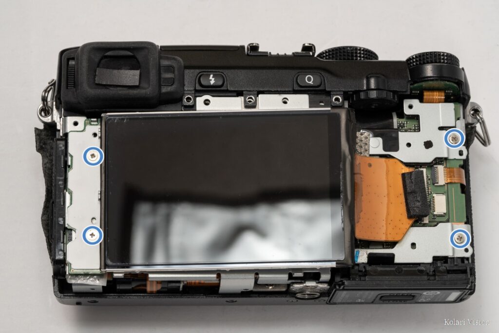
Step 11
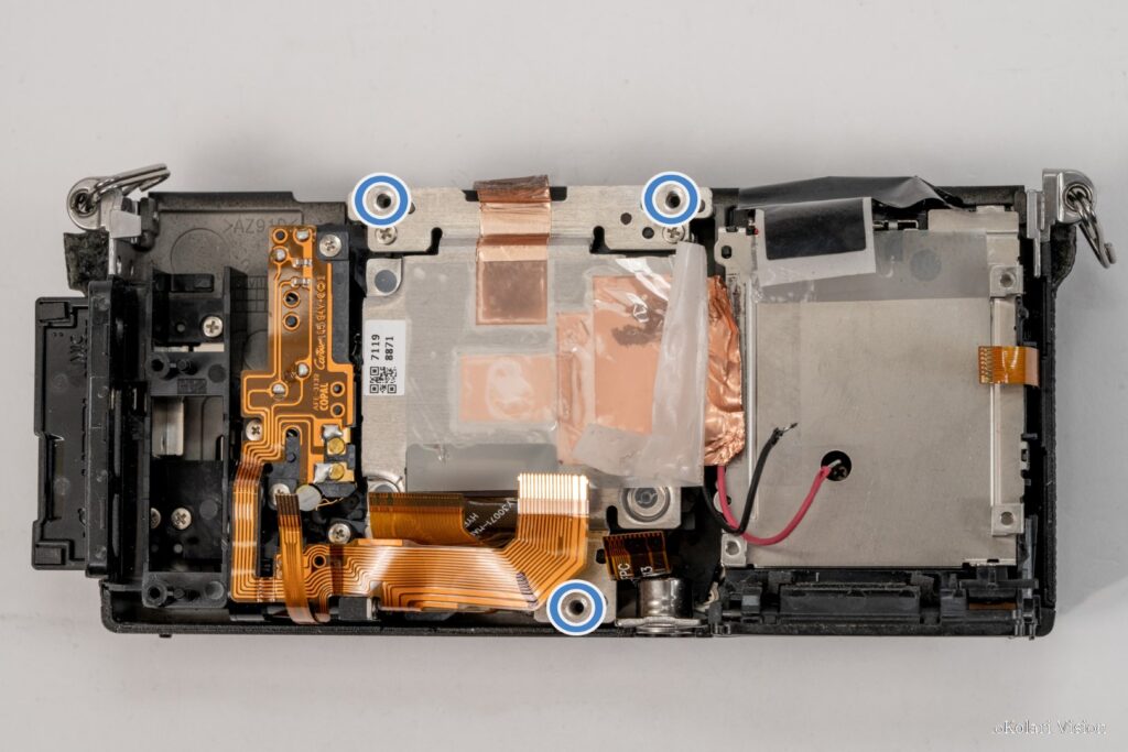
Remove the 4 screws on the left and right of the metal frame.
12
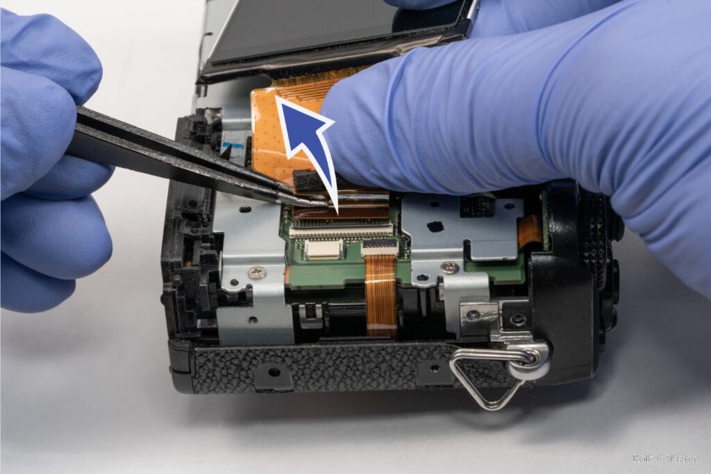
Step 12
Disconnect the large ribbon connect to the LCD screen and then take the screen off.
13
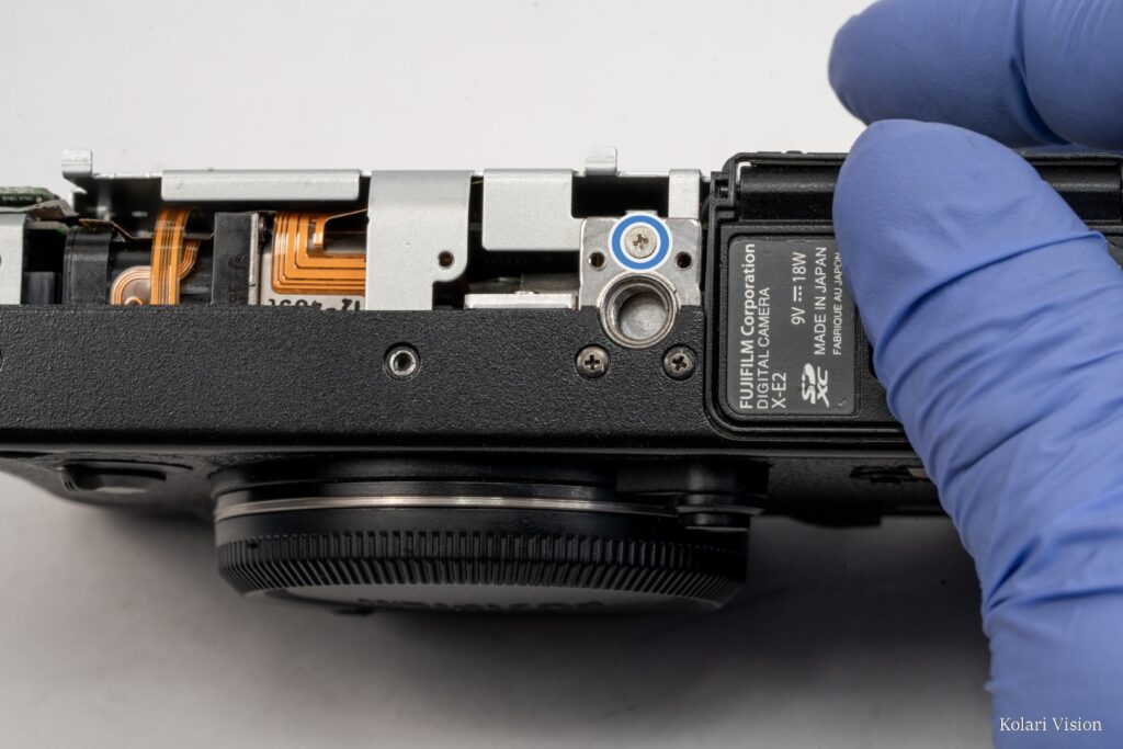
Step 13
On the bottom of the camera, remove the screw at the top of the tripod socket, connecting it to the metal frame.
14
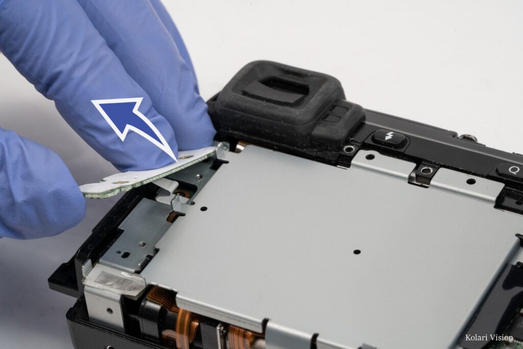
Step 14
On the back of the camera, lift the white plastic panel and circuit board off the metal frame, but be careful of the ribbon connecting it to the board. Gently move the board to the side.
15
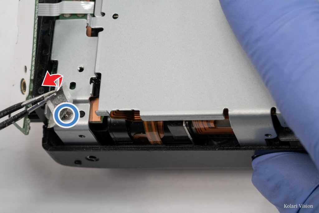
Step 15
Peel back the tape that was hiding beneath the board and remove the screw that it was covering.
16
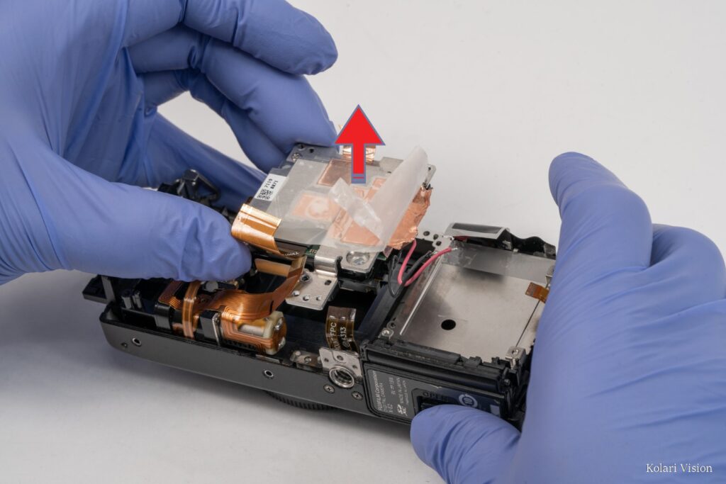
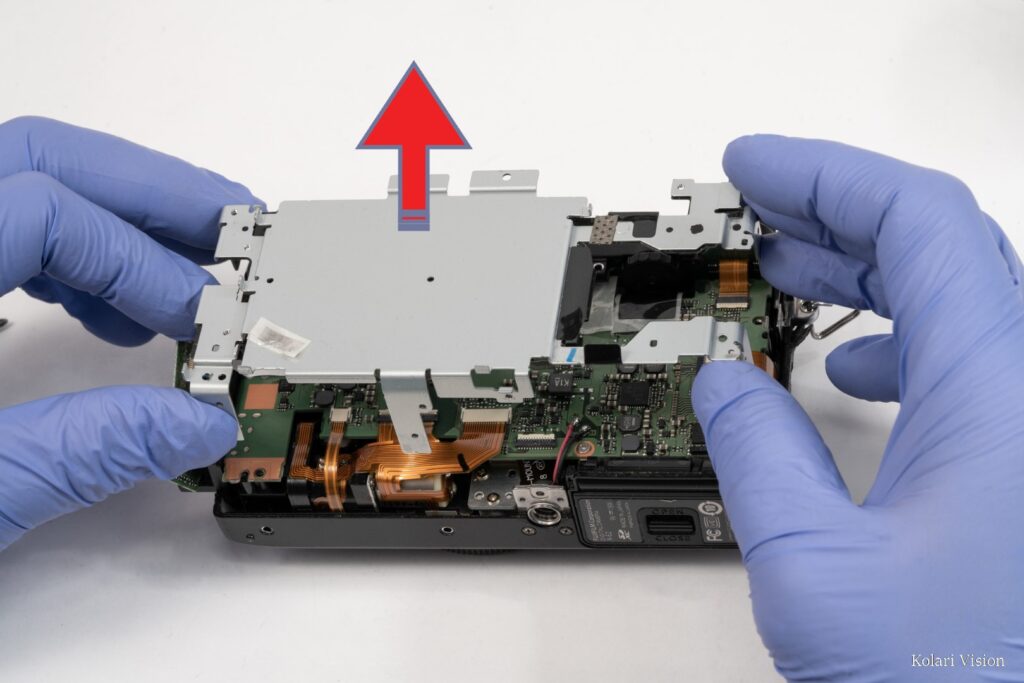
Step 16
Take off the metal frame.
17
Step 17
Slide the metal bar at the thin metal bar at the top, and peel back the tape beneath the Q button, revealing 4 wires. Desolder the four wires.
18
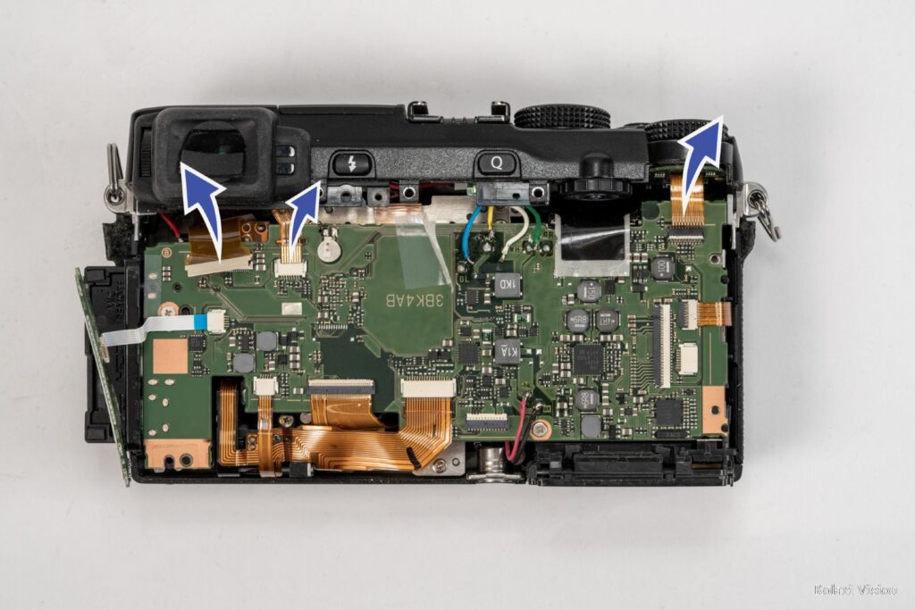
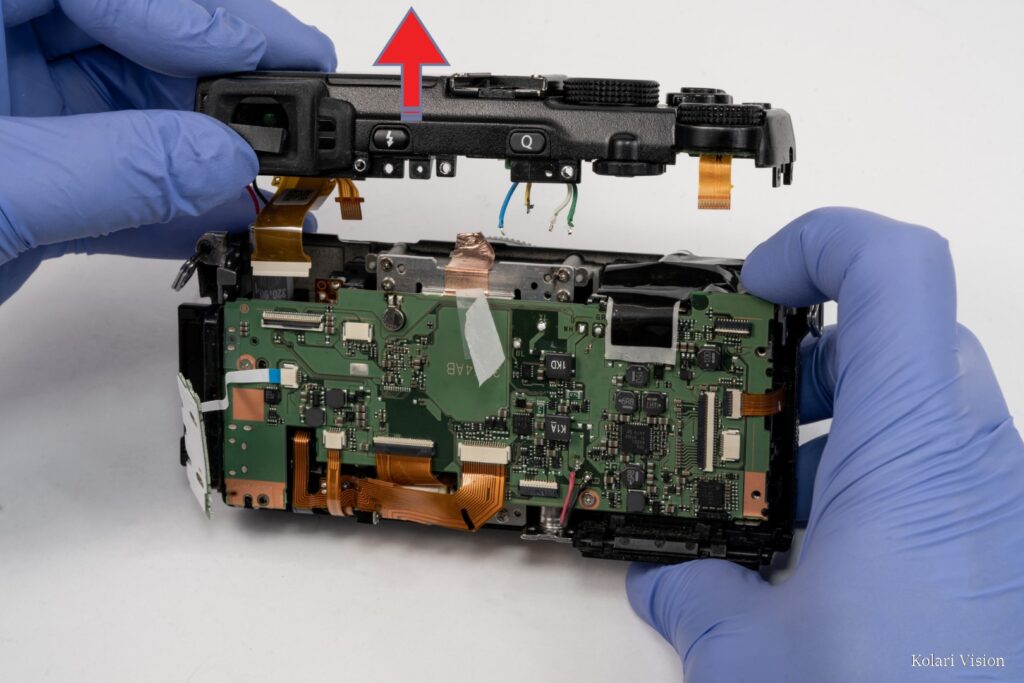
Step 18
Disconnect all 3 ribbons at the top.
19
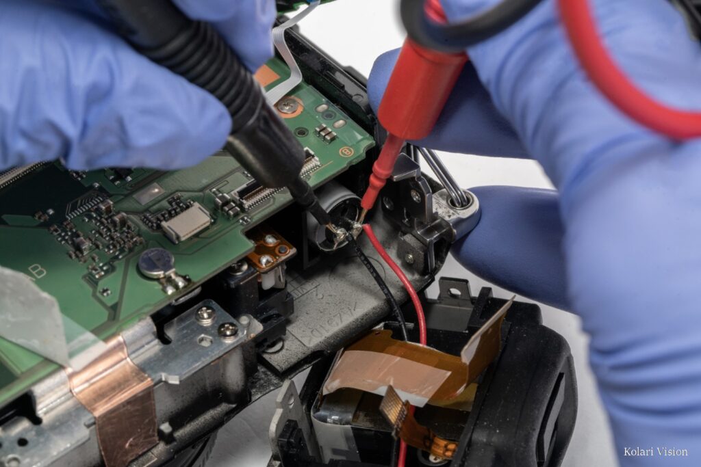
Step 19
Pull the top piece separate. Drain the capacitor using a discharge tool before proceeding further. Failure to properly drain the capacitor can result in electric shock.
20
Step 20
Pull off the top section with the drained capacitor still attached.
21
Step 21
Peel back the tape at the top-right revealing 4 wires. Desolder all 4 wires, as well as the lower 2 above the tripod socket.
22
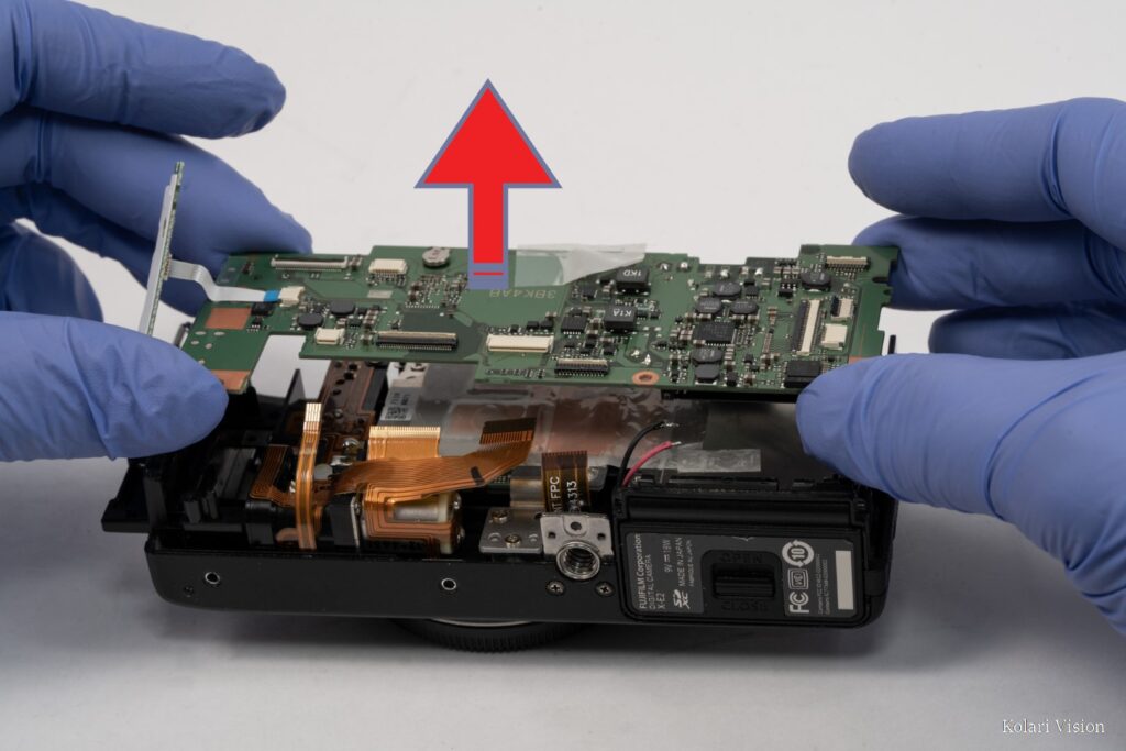
Step 22
Remove the remaining 2 screws on the board. Disconnect the ribbons connected to the motherboard. For the long one across the bottom, we advise removing the screw holding it down to allow more flexibility.
23
Step 23
Lift off the circuit board.
24
Step 24
Peel back the white film and the bronze heat tape.
")
")
")
")
")
")
")
")
")
")
")
")
")
")
")
")
")
")
")