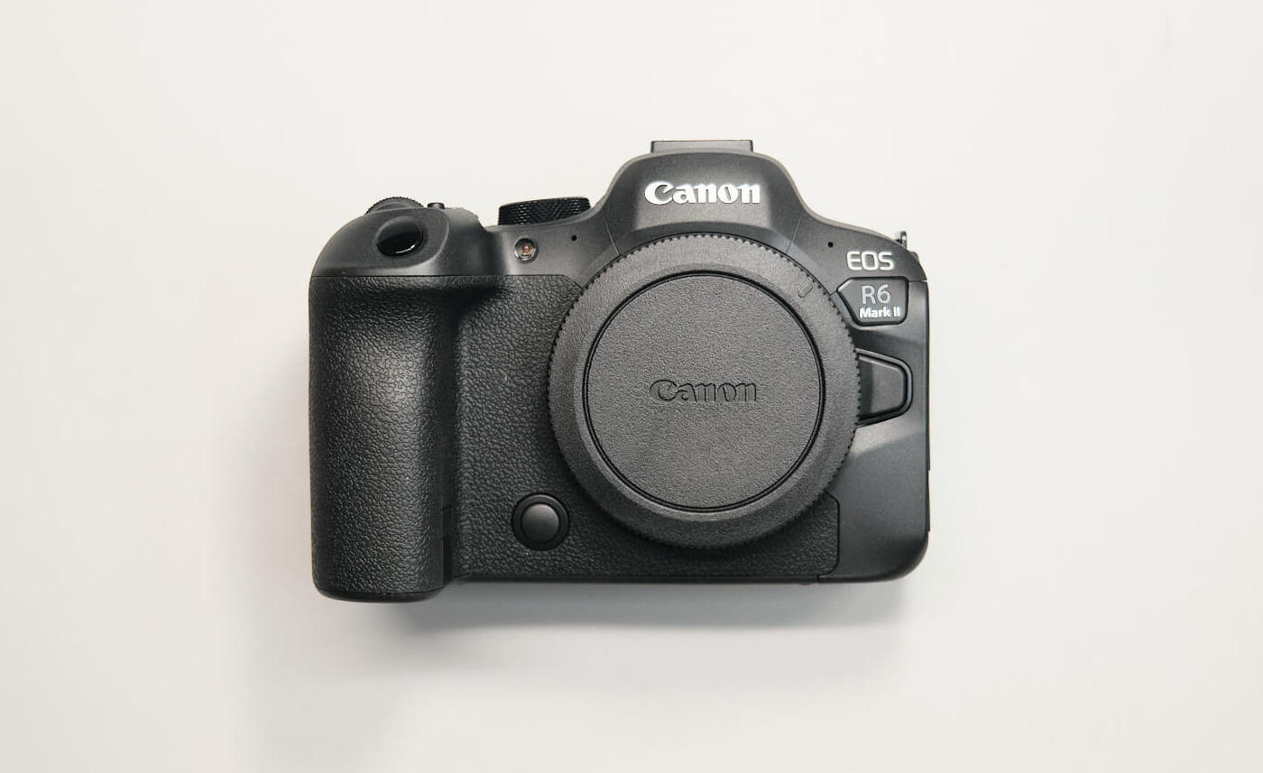
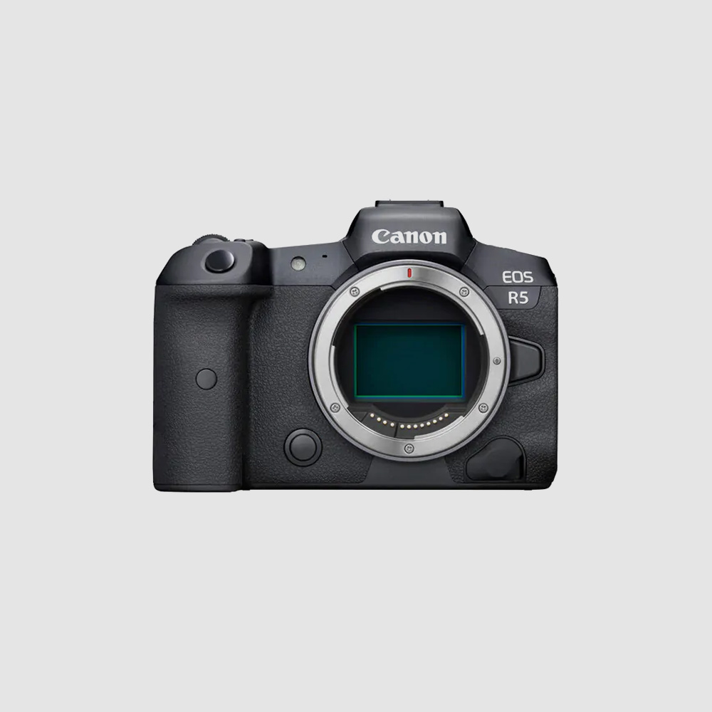
Since the release of the original Canon EOS R6, Canon has decided to roll out a new version of the high-end professional digital camera: the Canon EOS R6 MK II. You might wonder, “Why didn’t they just make a new camera?” While there are many similarities between the two cameras, the differences make the upgrade worth considering. Let’s look at the camera’s design and function before we disassemble and tear it down.
The exterior design of the camera is more or less the same as the original Canon EOS R6, but the new internals is where we see the substantial differences. The original EOS R6 has a modest 20MP Full-Frame CMOS Sensor; the MK II upgrades its sensor to a more contemporary 24.2MP Full-Frame CMOS Sensor to hang with the competition. The Canon EOS R6 MK II also improves its video capabilities compared to the original, including better thermals and recording time for 4k/60p video in either full-frame or APS-C mode (up to 40 and 50 minutes, respectively). Other improvements include better autofocus, faster burst shooting, and a new mode called ‘Moving Subject HDR.’
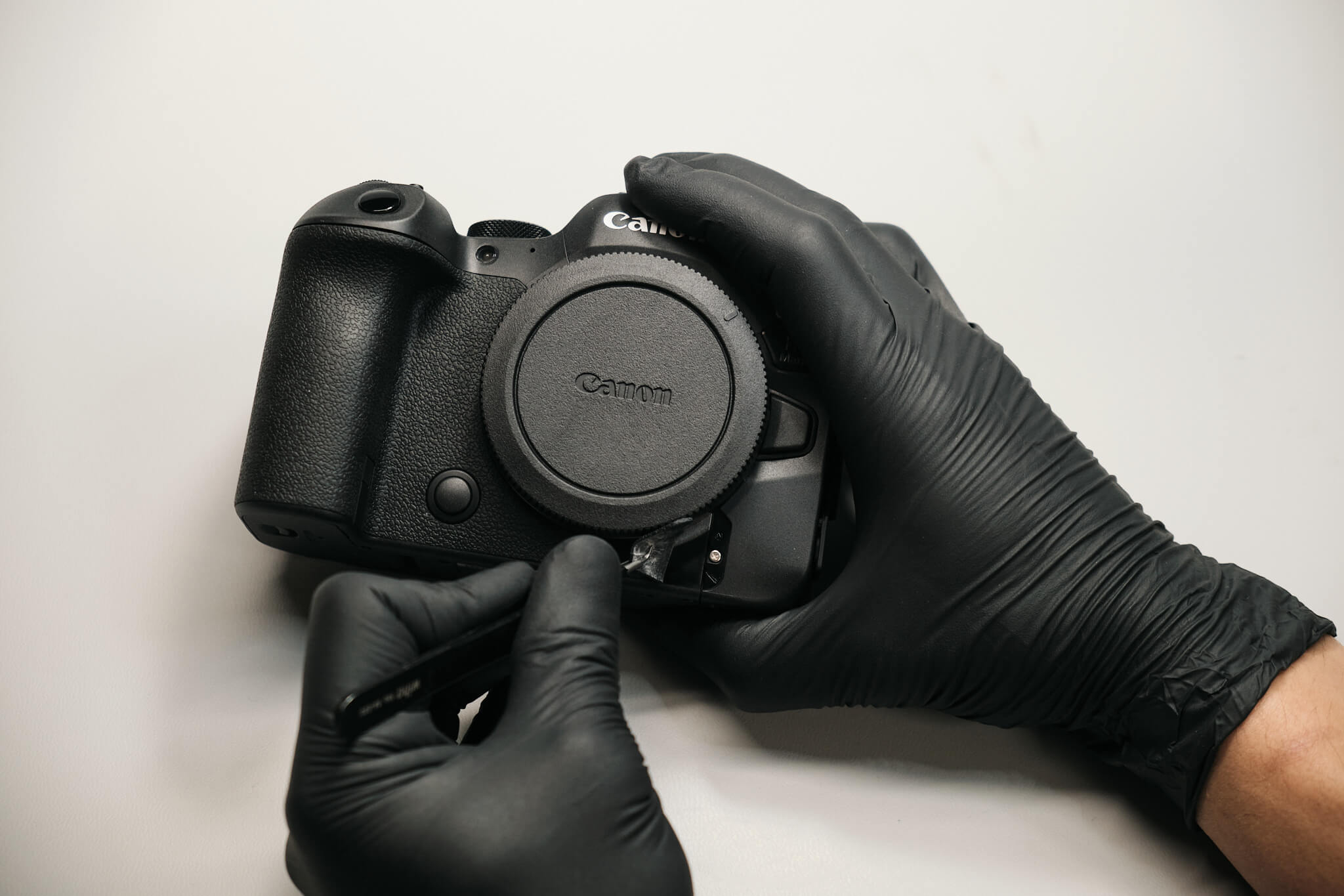
With all of that out of the way, let’s dig into this teardown!
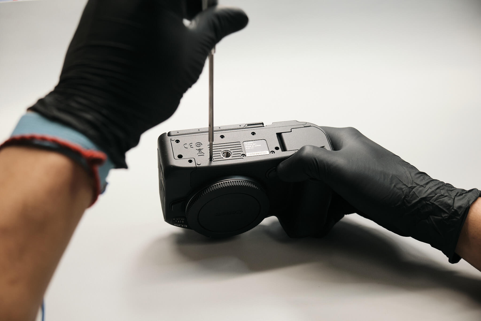
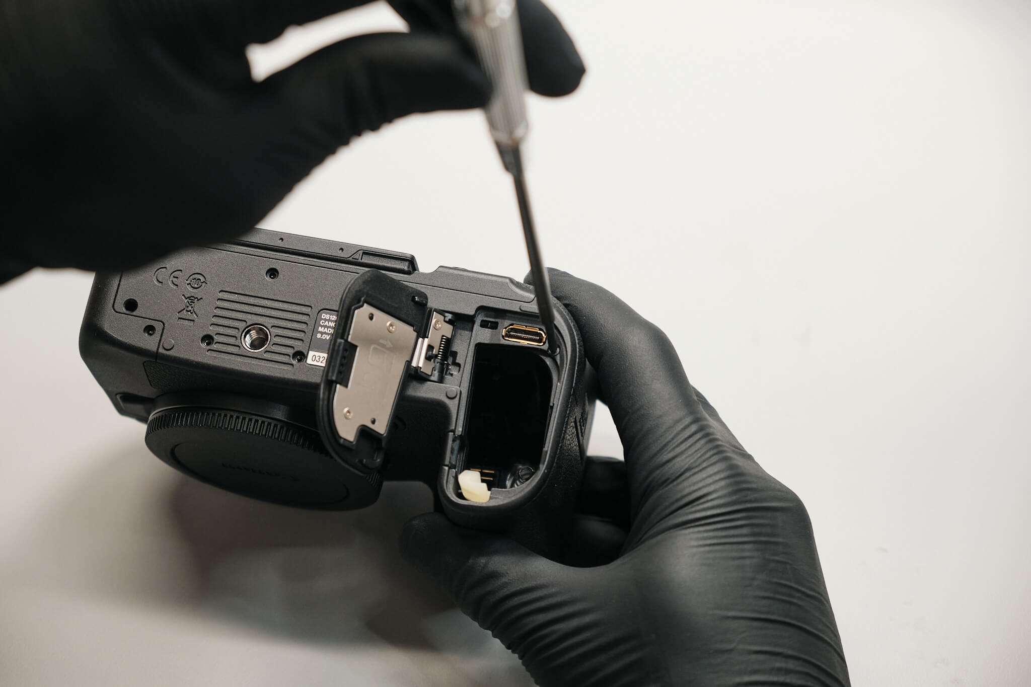
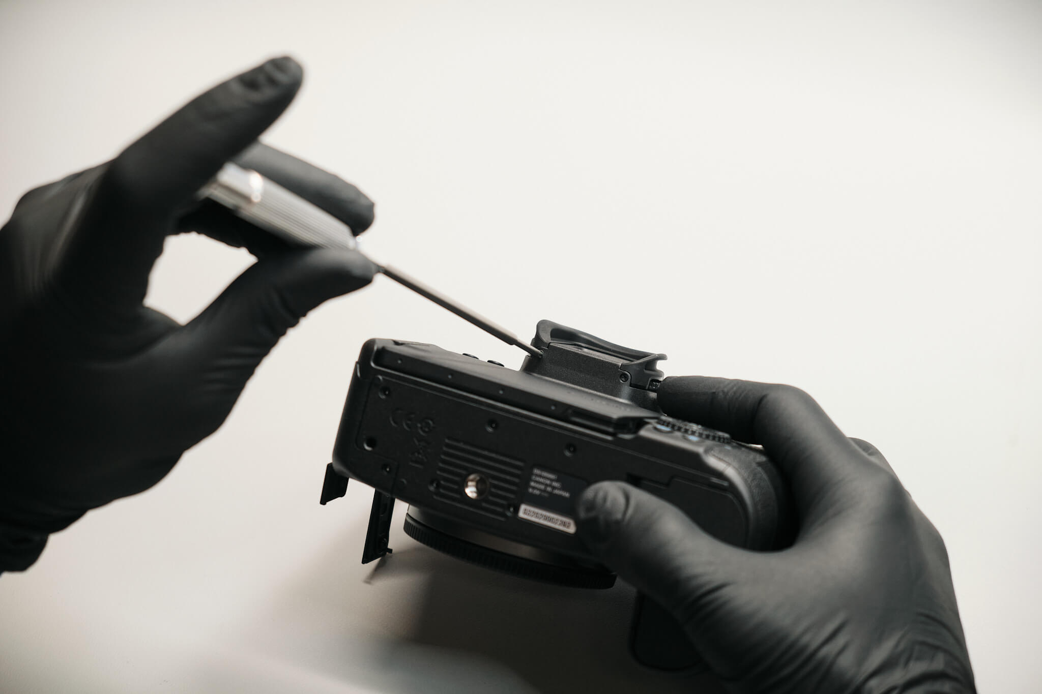
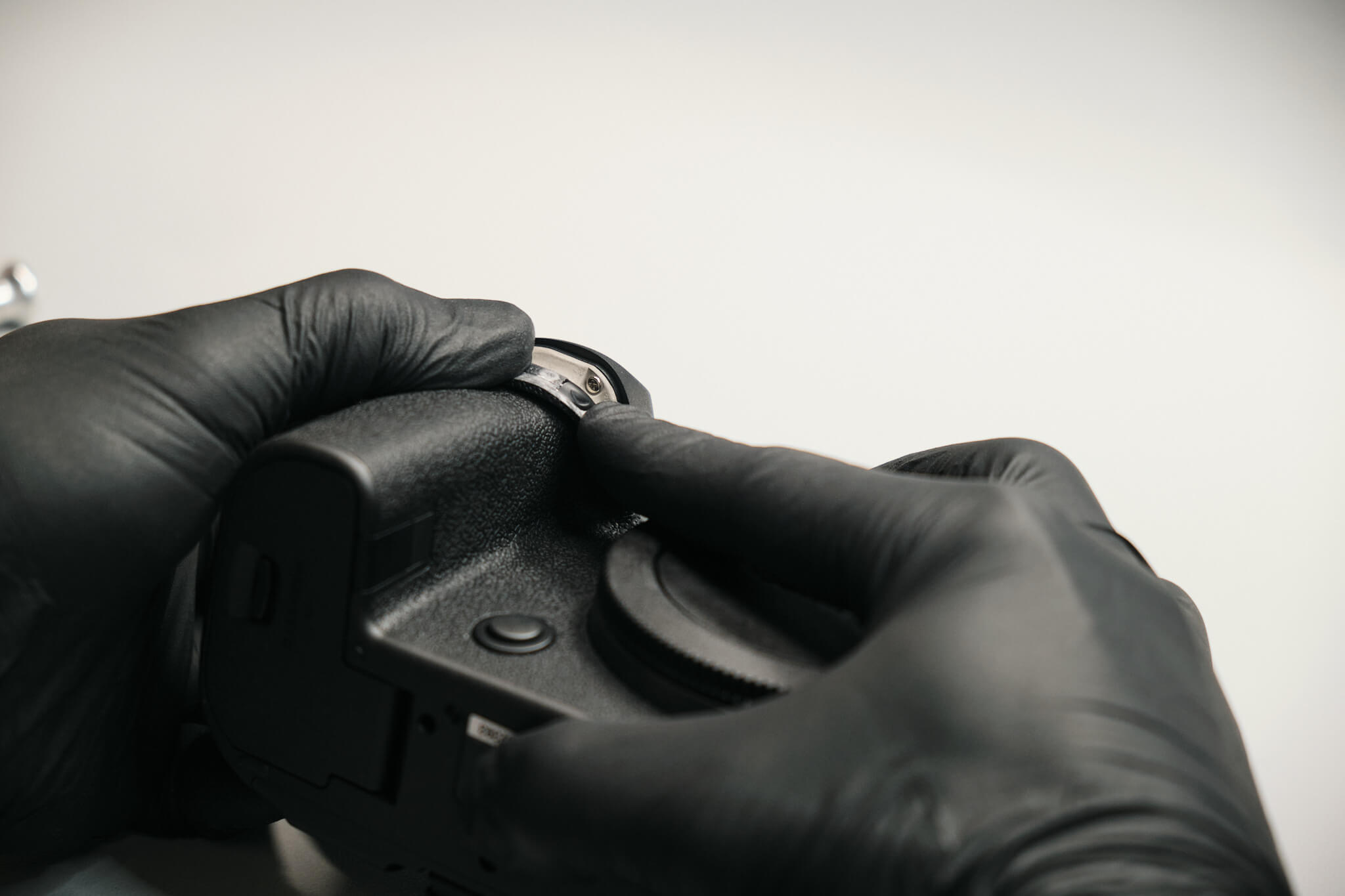
First, we remove the seven screws at the bottom of the camera, along with a screw under the battery door cover. The rubber grip of the handle needs to be peeled back to reveal one hidden silver screw.
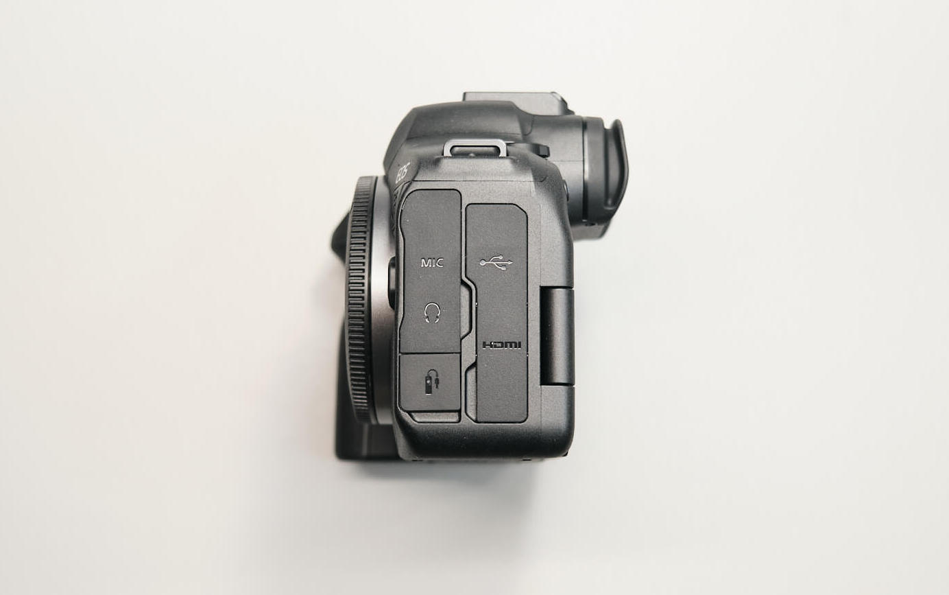
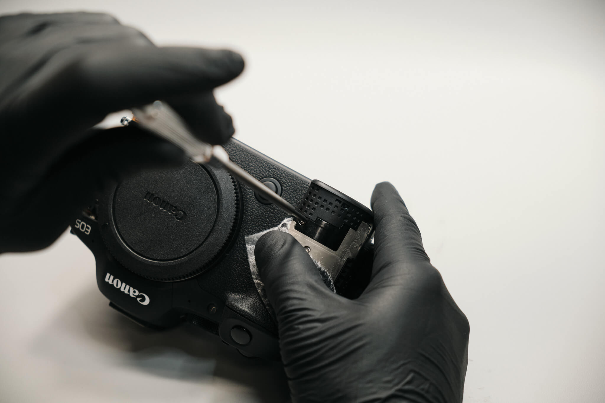
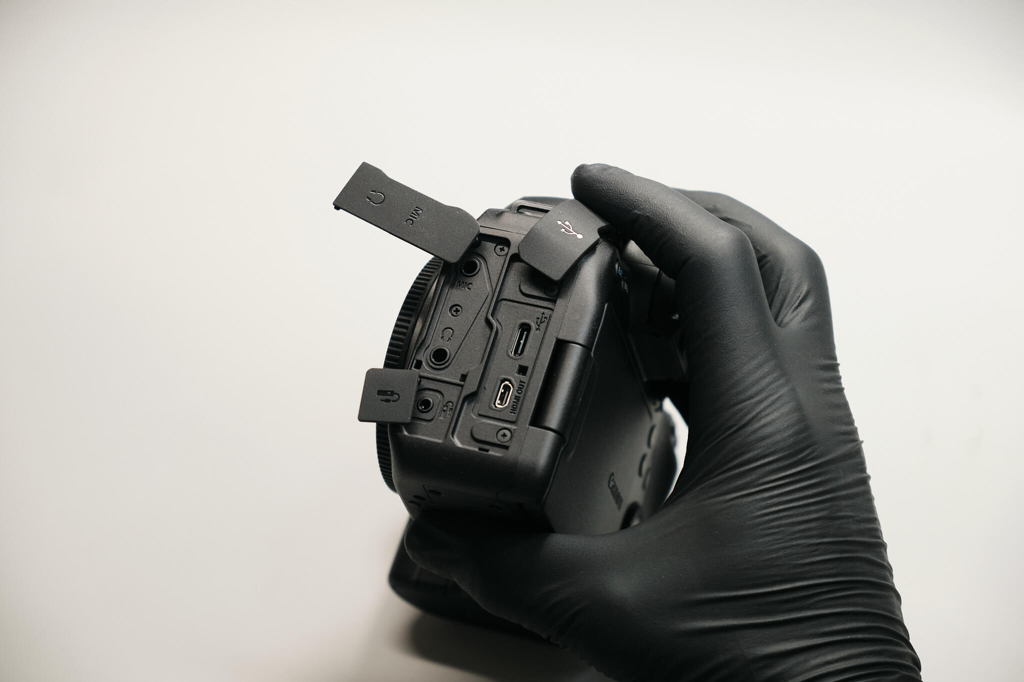
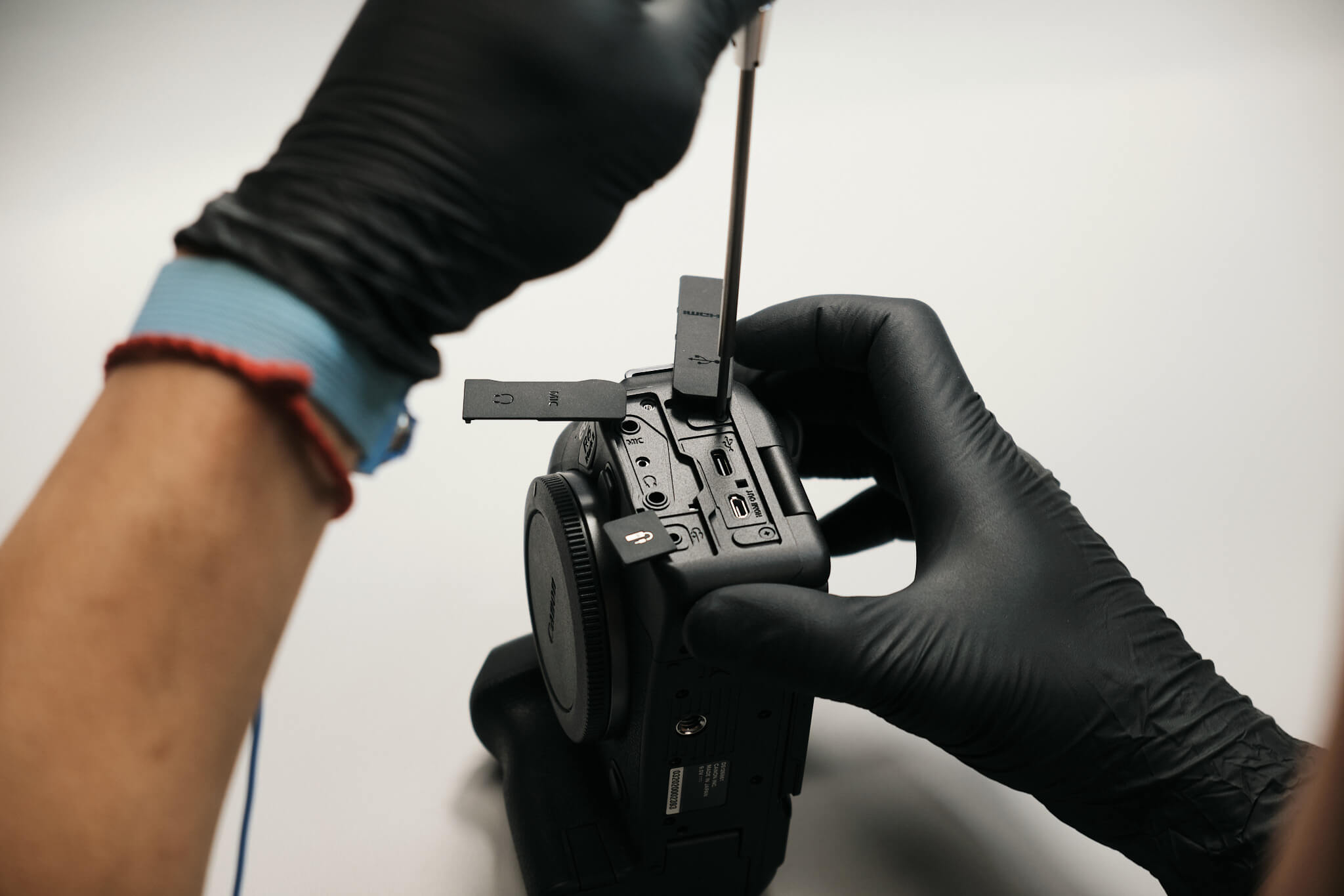
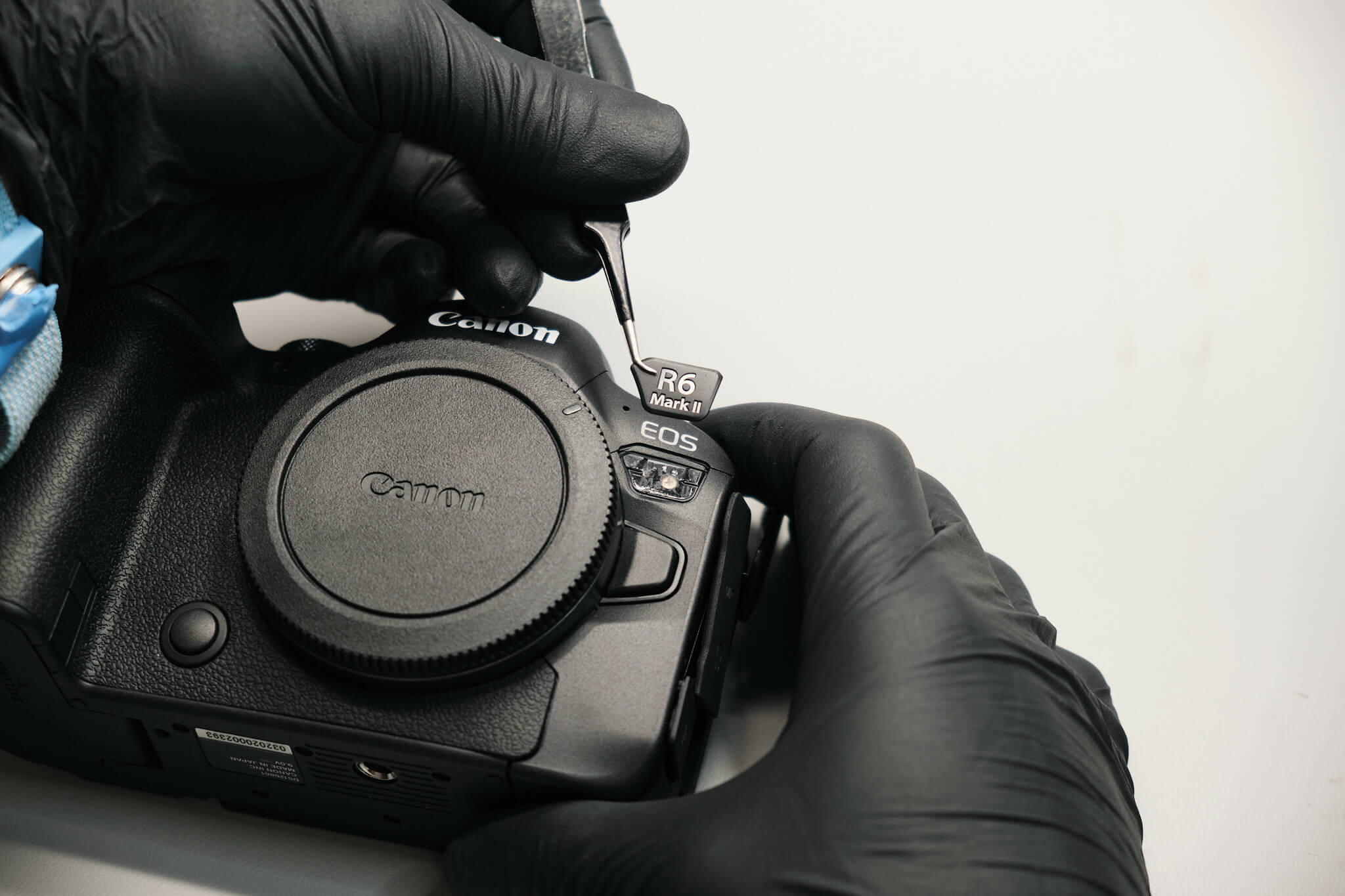
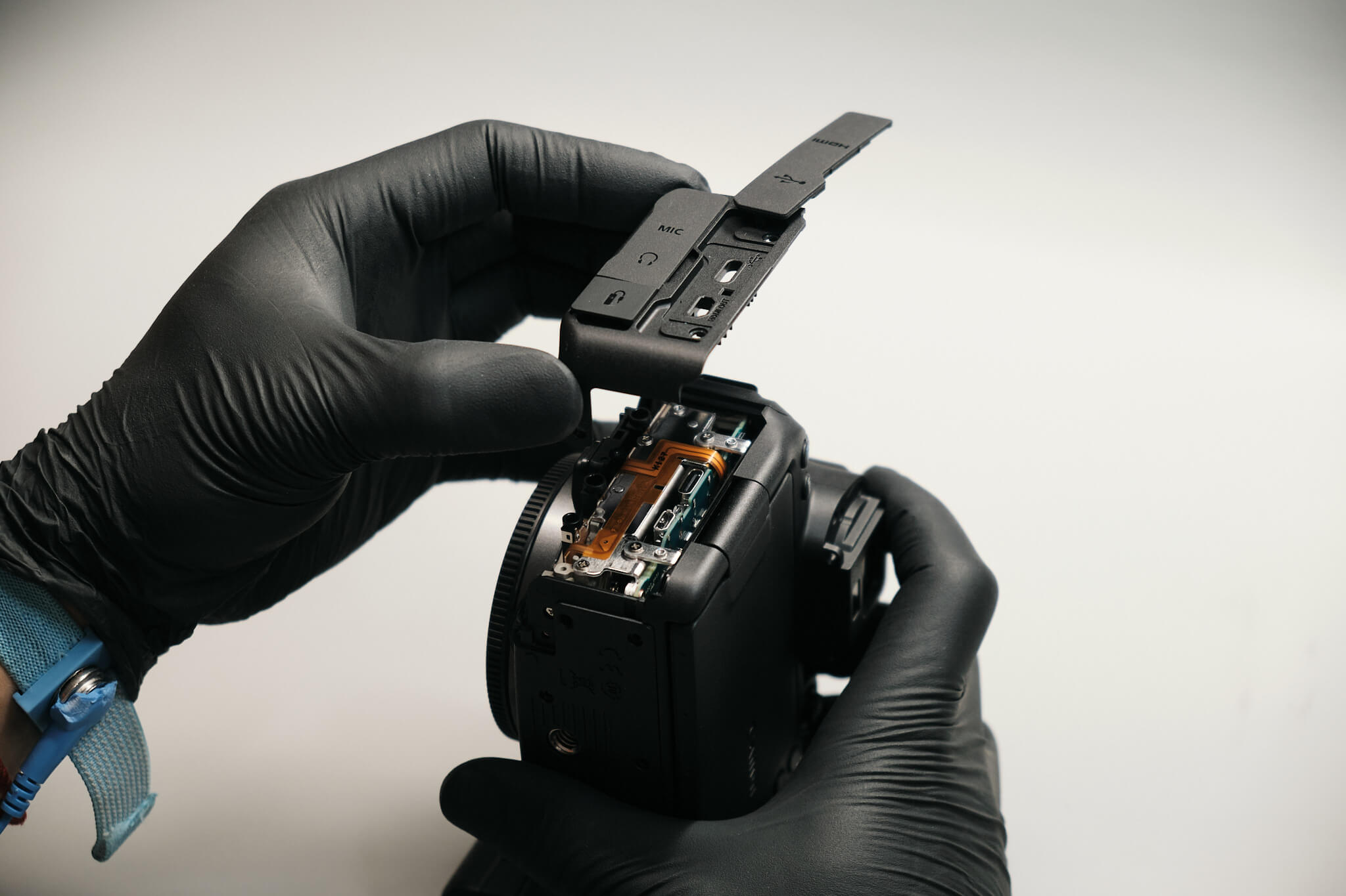
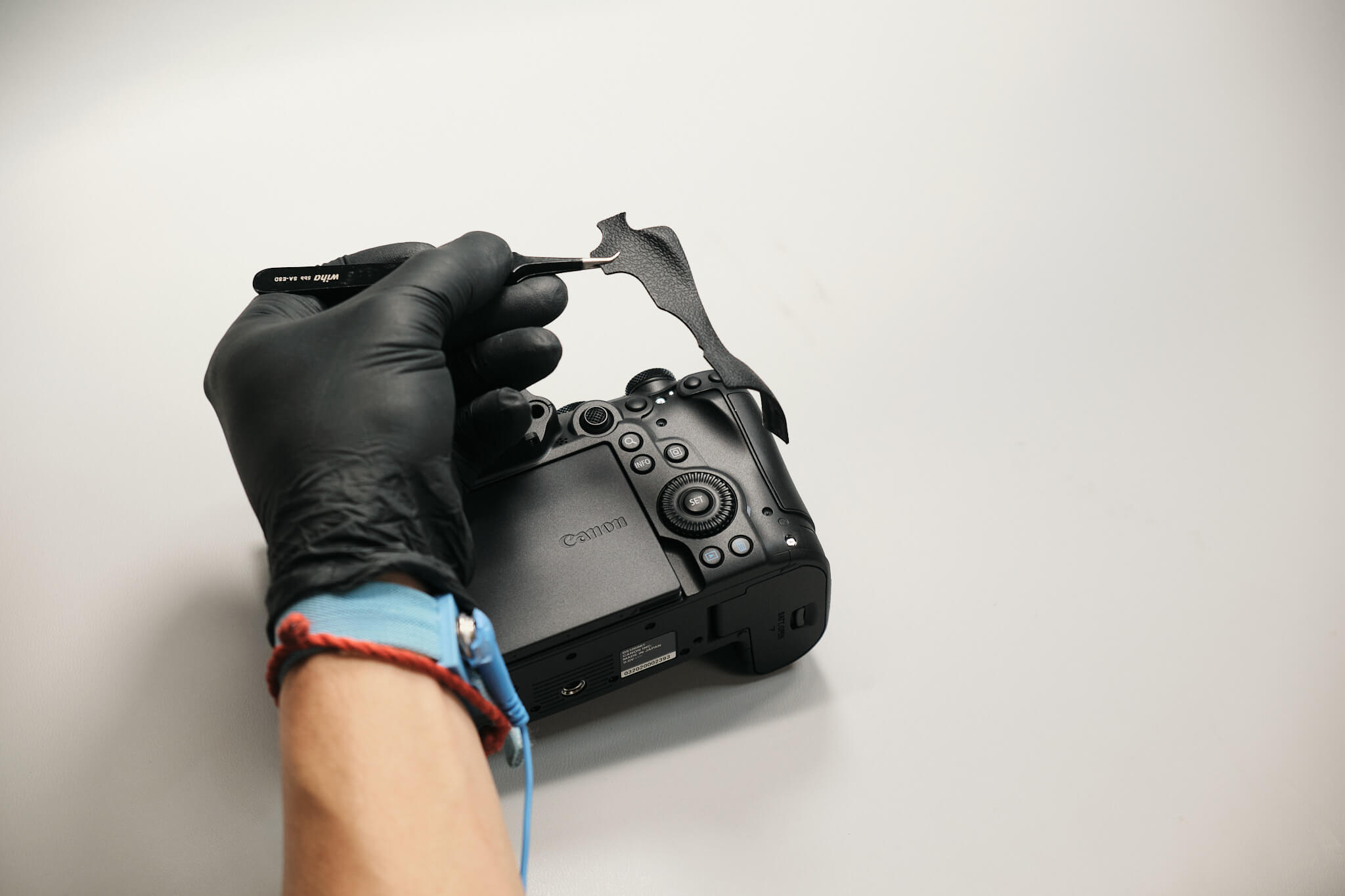
We pop off the dust caps on the left side of the camera and remove four screws, allowing us to remove the port cover. Peeling back the rubber below the lens mount and R6 MK II emblem reveals a hidden screw underneath each part.
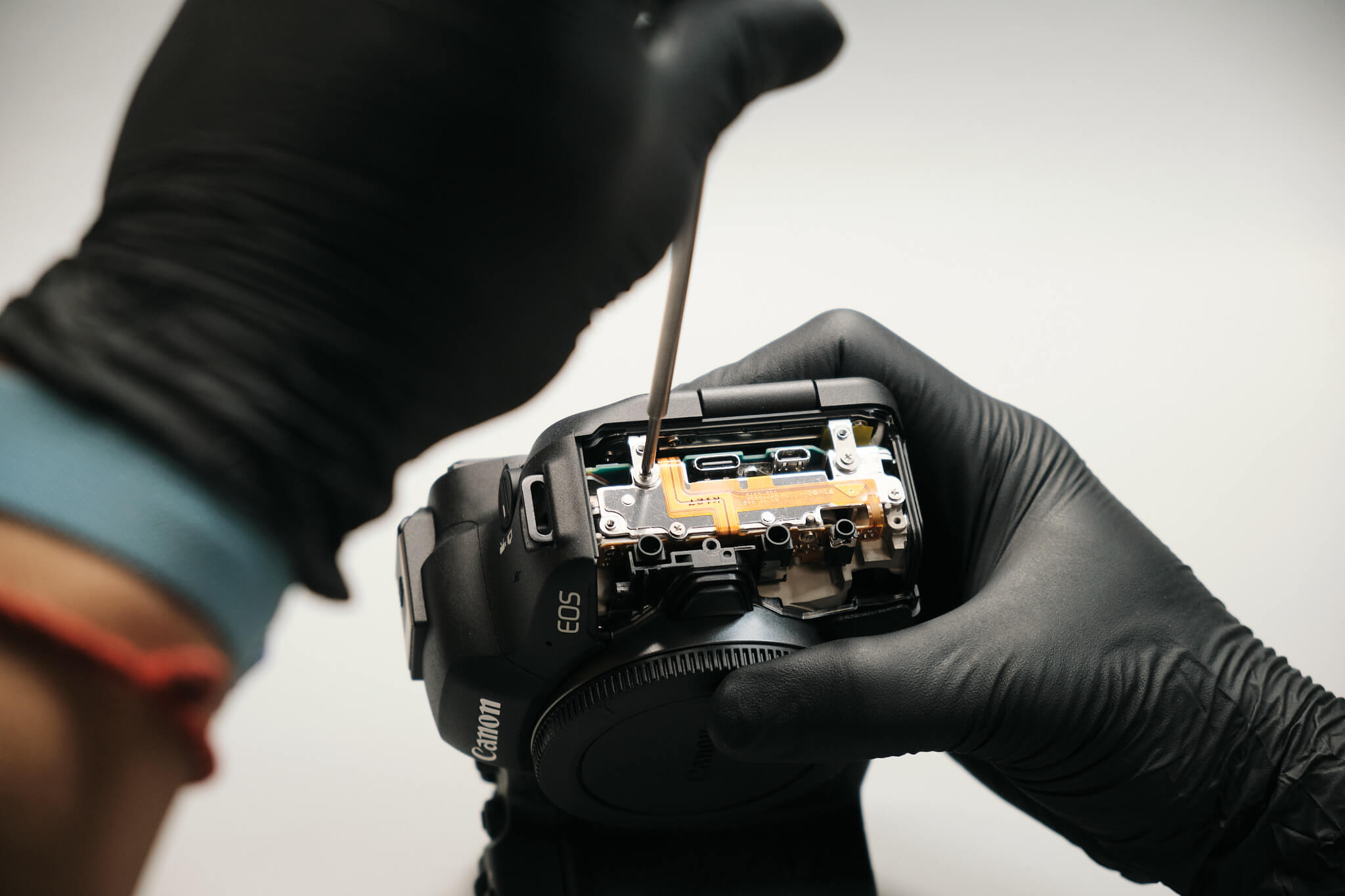
Under the port cover, two screws need to be removed. These screws hold down the rear panel bracket.
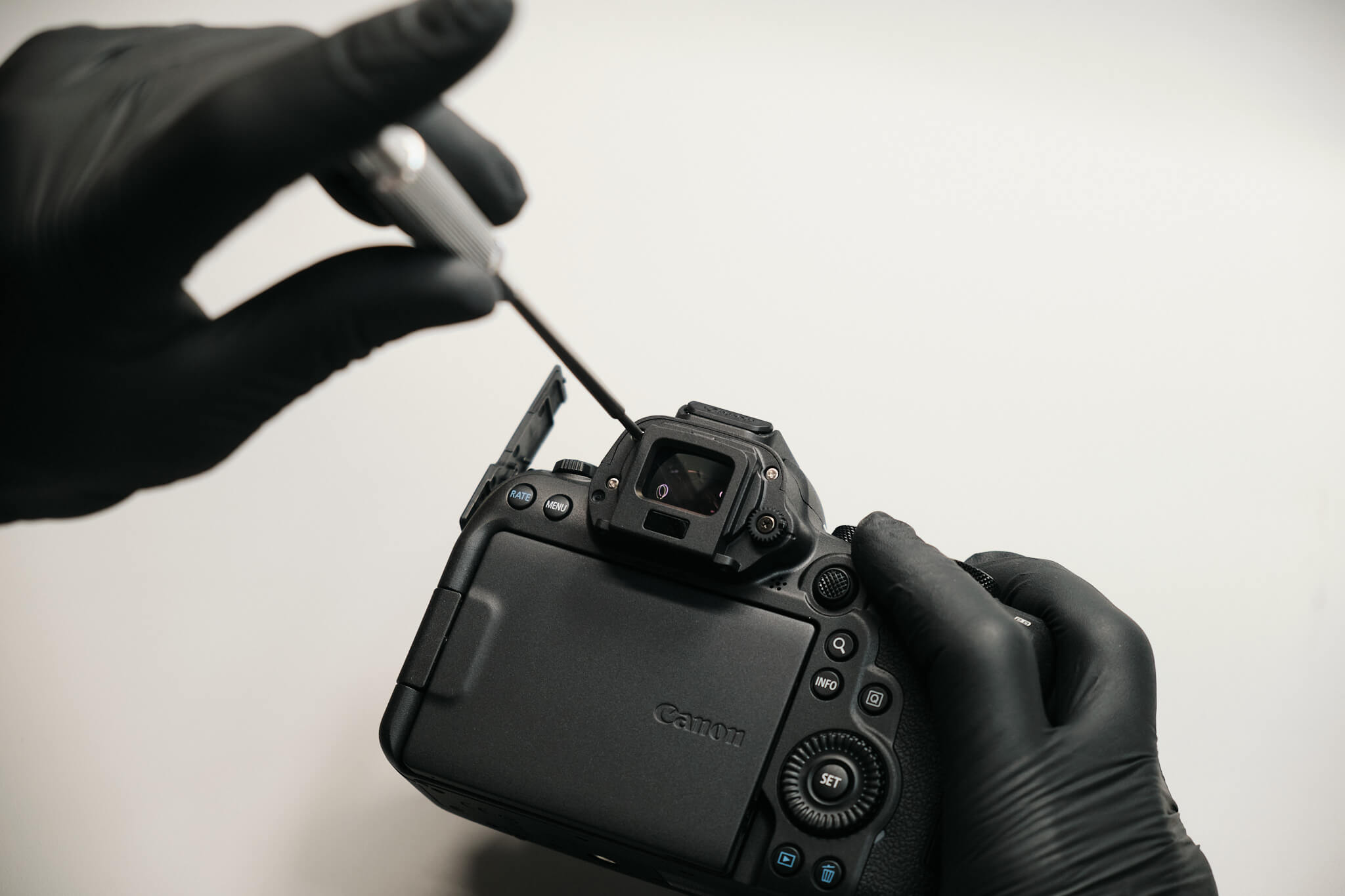
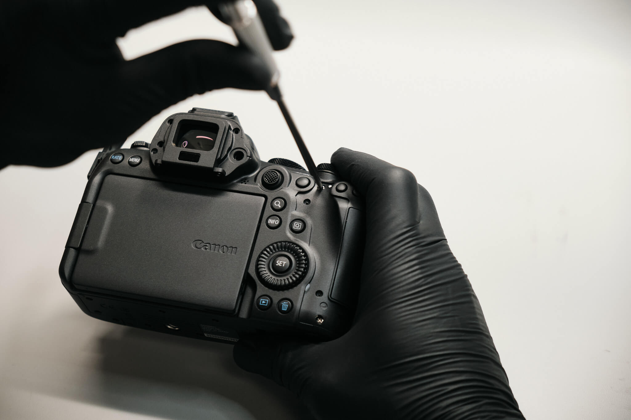
The eyecup is held down with two screws. Once that is removed, we can see that three screws keep the entire EVF system in place. The dioptric adjustment knob can be removed.
Peeling off the thumb grip exposes two screws.
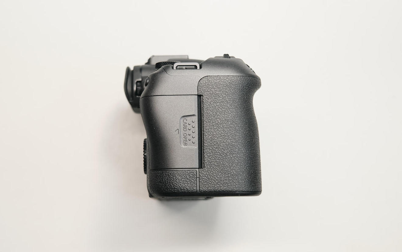
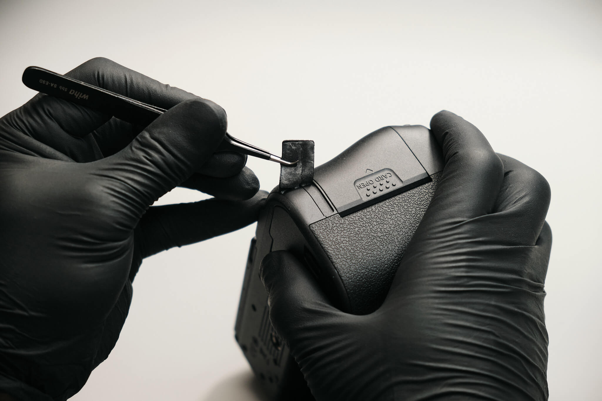
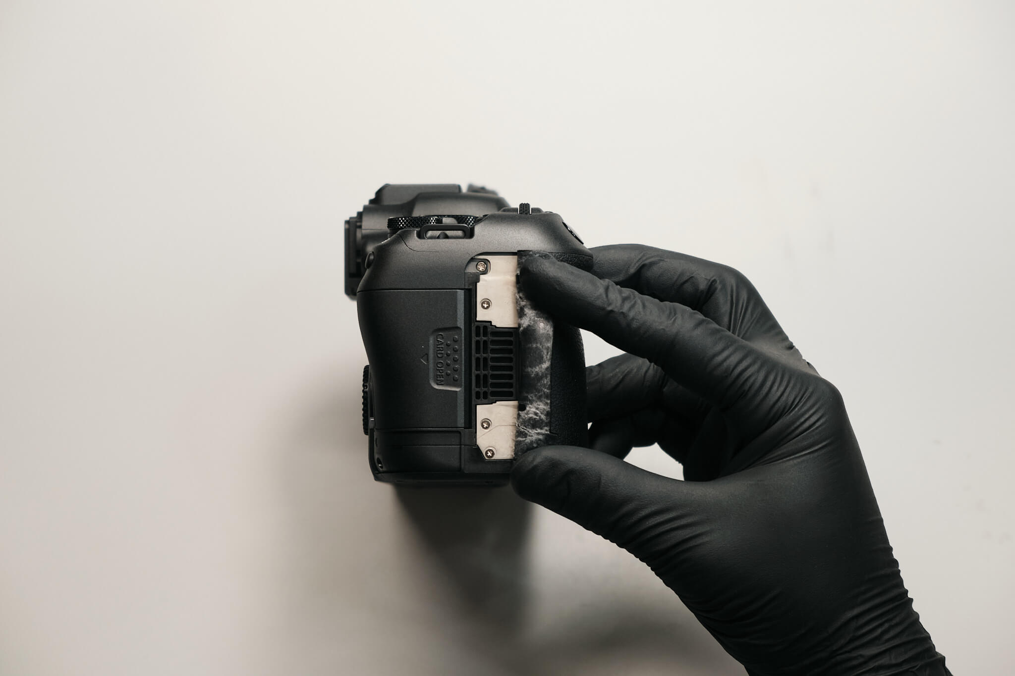
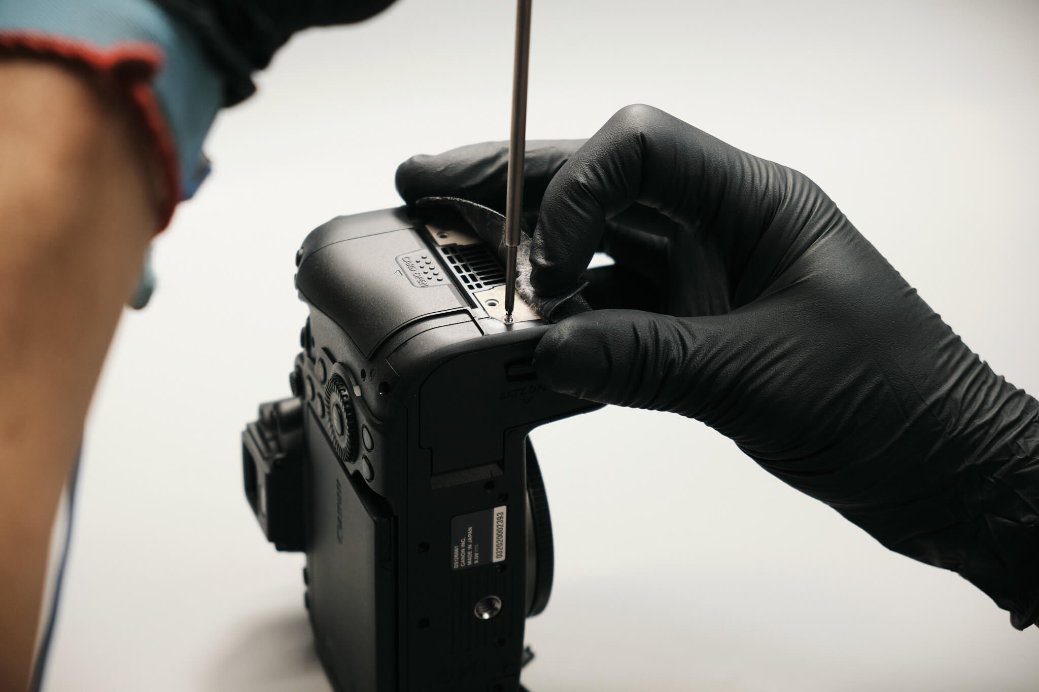
To the right side of the card slot cover, we peel back the rubber grip and remove four silver screws. There is one more screw below the shutter release button and on the right handle of the camera.
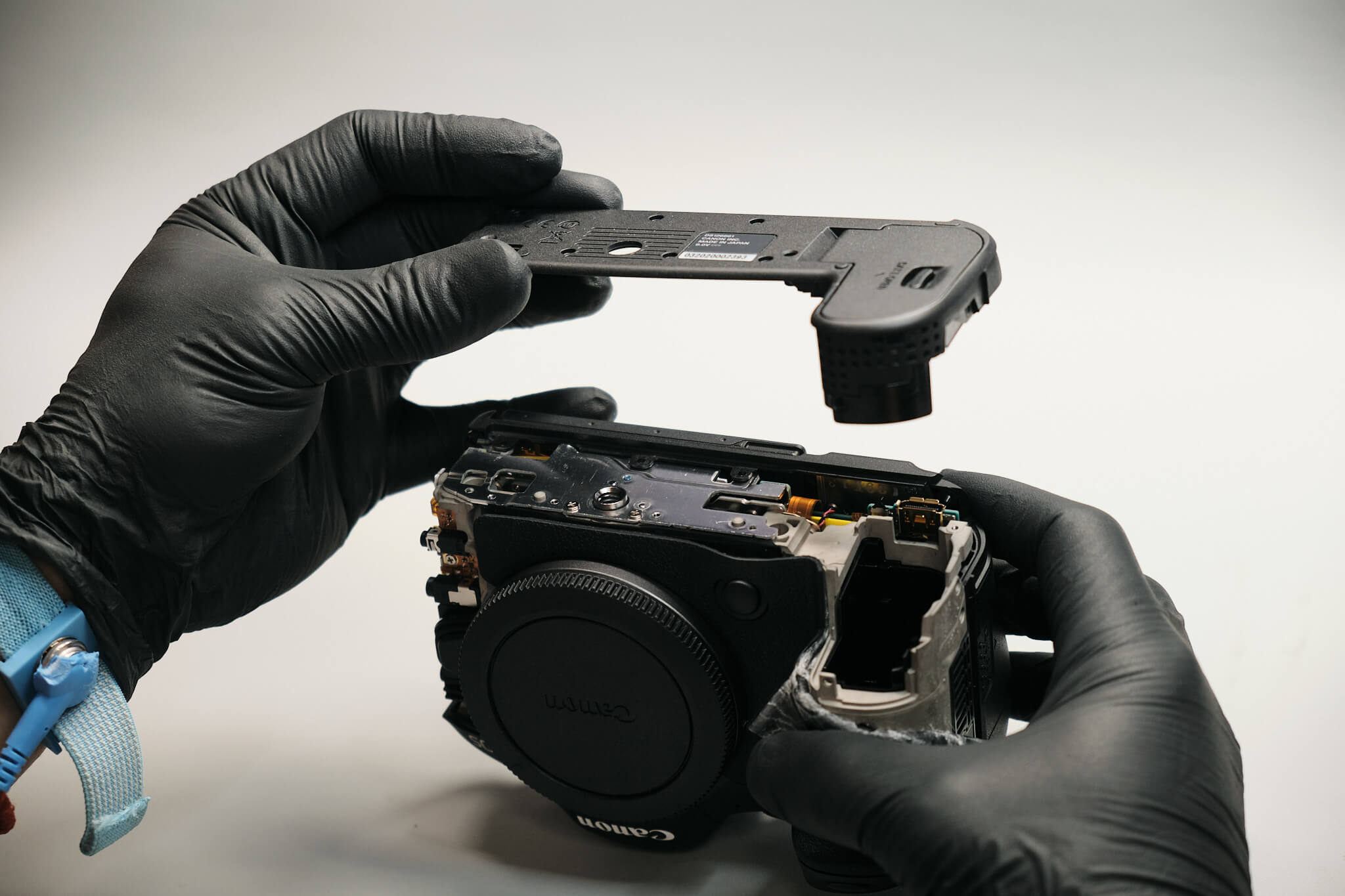
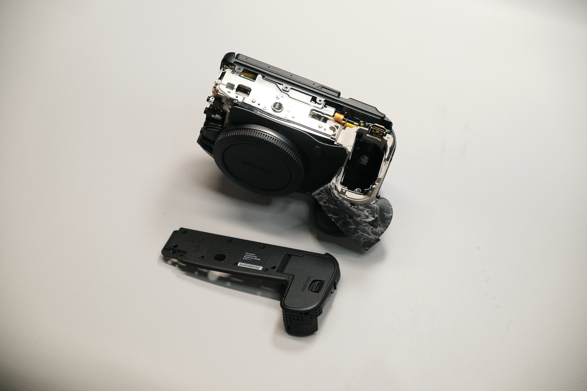
We remove the bottom cover to prevent damage to the interlocking switch on the circuit board.
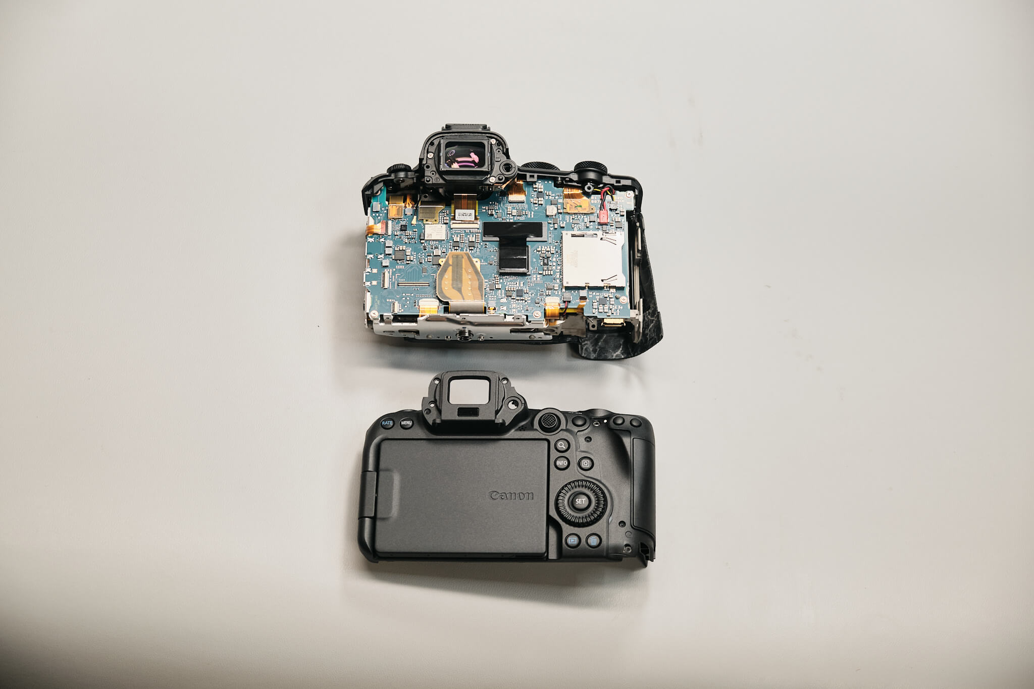
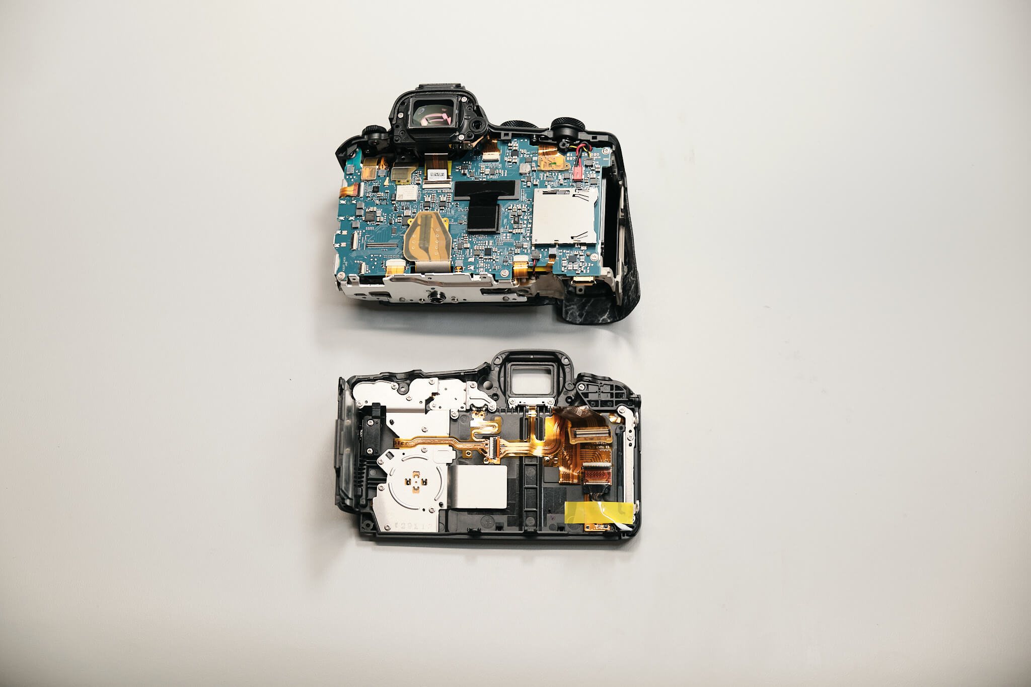
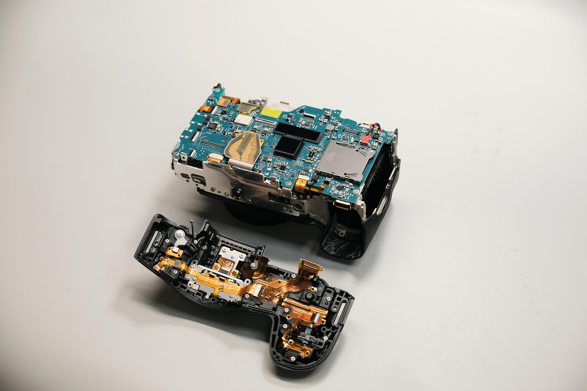
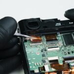
Disconnecting the rear panel ribbon cable from the circuit board allows us to remove the entire back panel and fully exposes the circuit board.
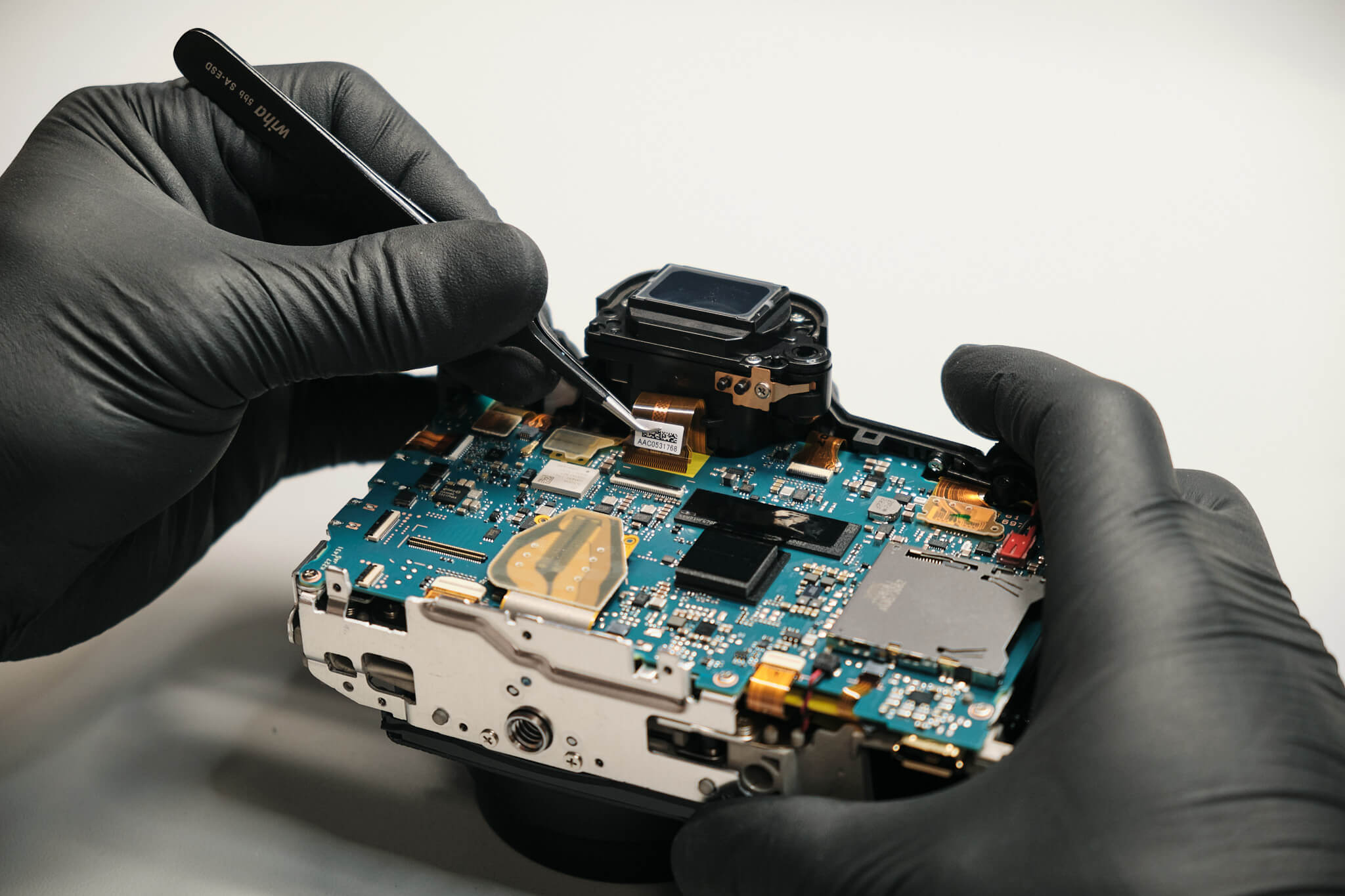
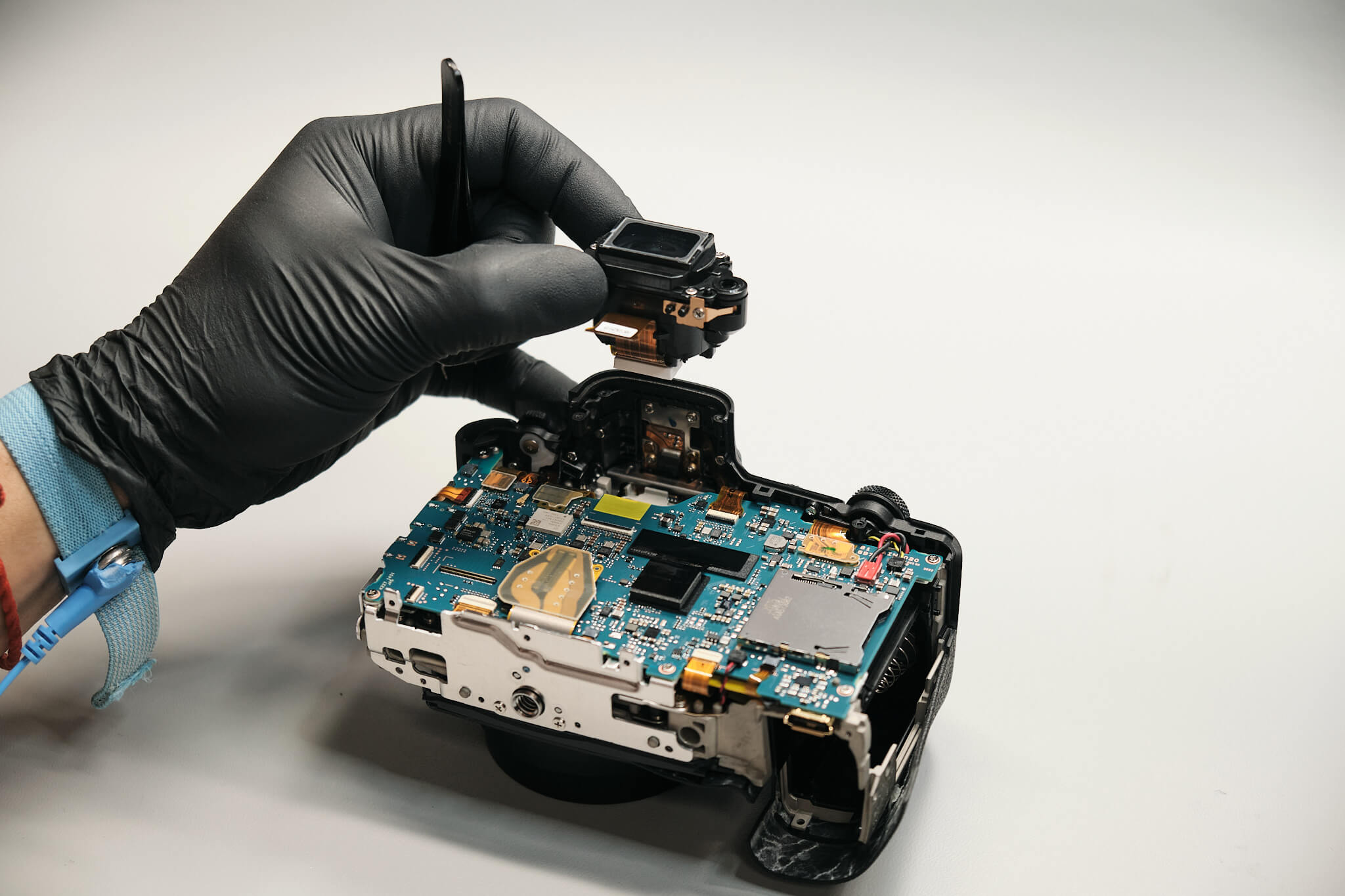
One ribbon cable connects the EVF to the circuit board. Removing it disconnects the EVF.
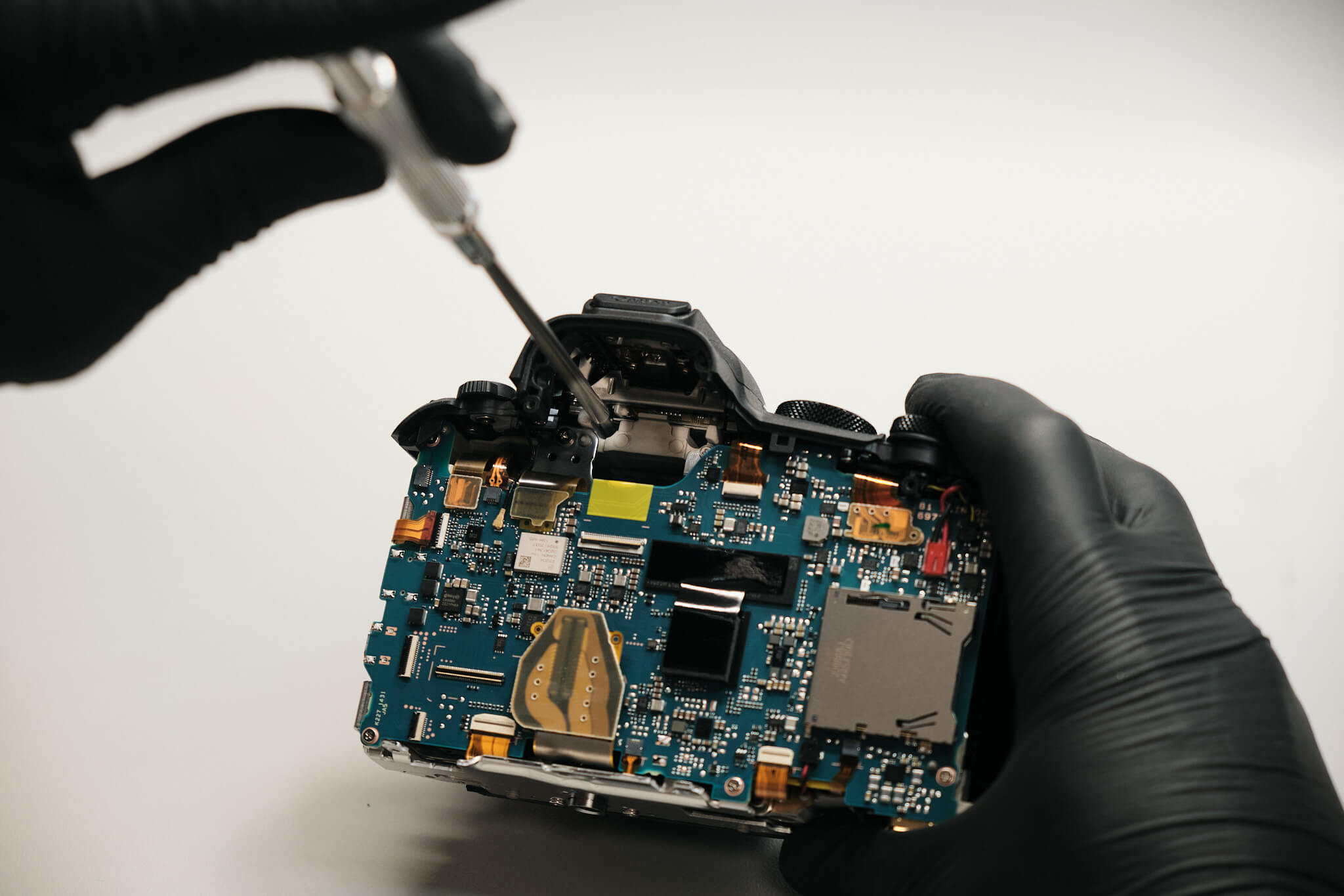
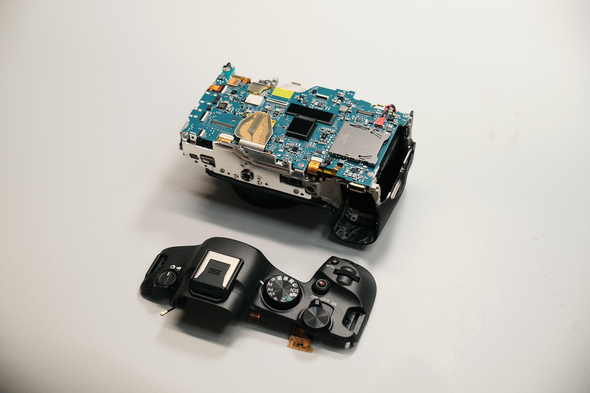
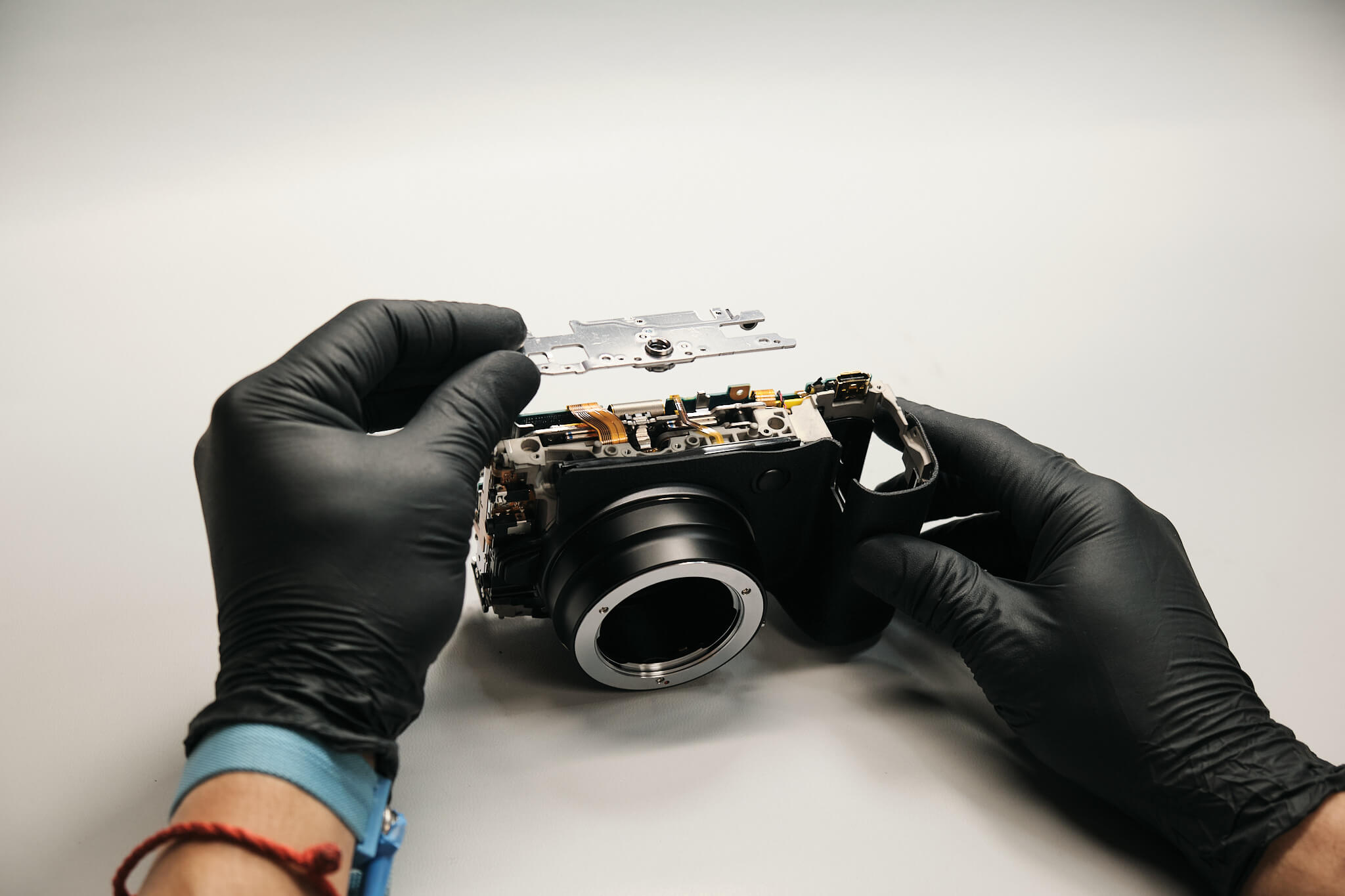
Two screws below the hot shoe need to be removed. Removing these screws and the coaxial cable and two ribbons allows the top panel to disconnect from the camera body.
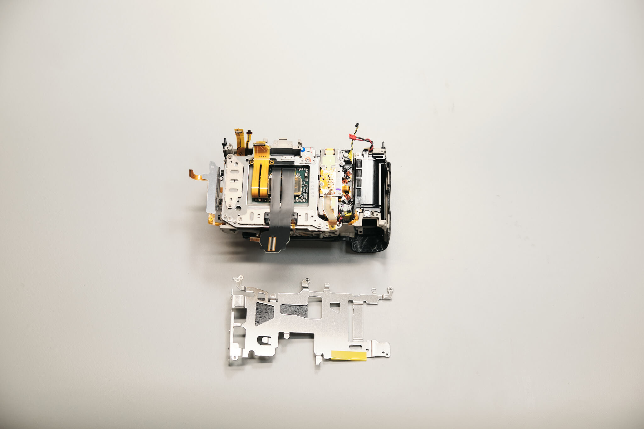
The bottom bracket is only held in place by four screws.
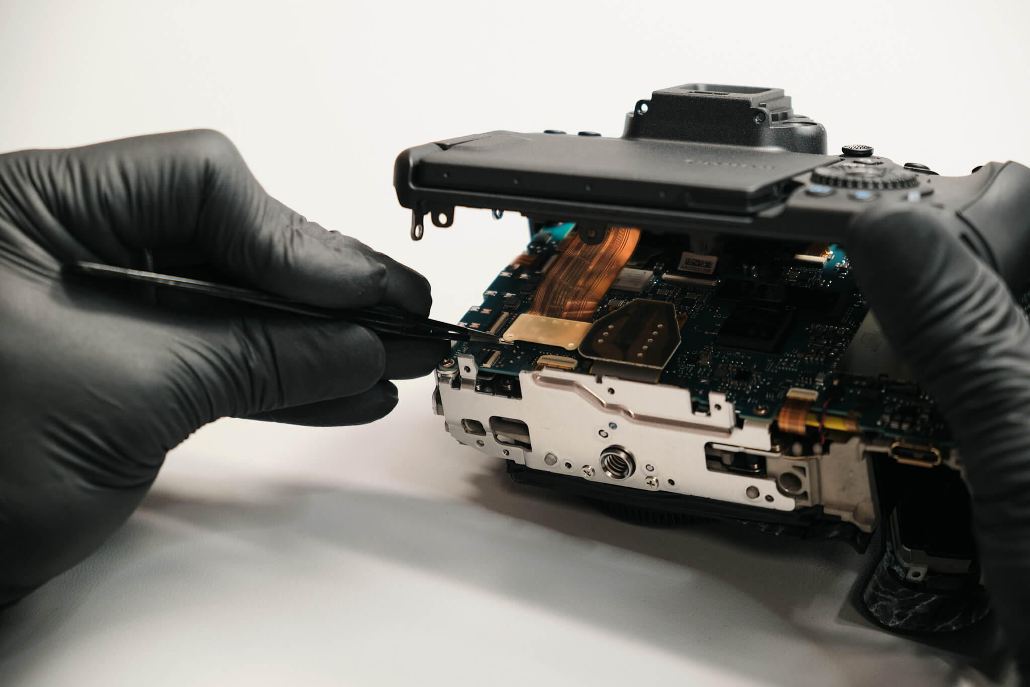
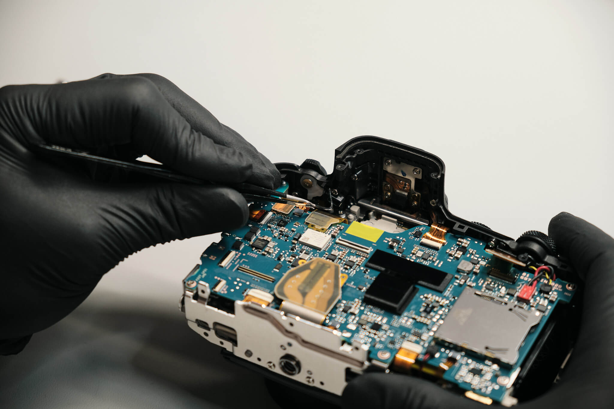
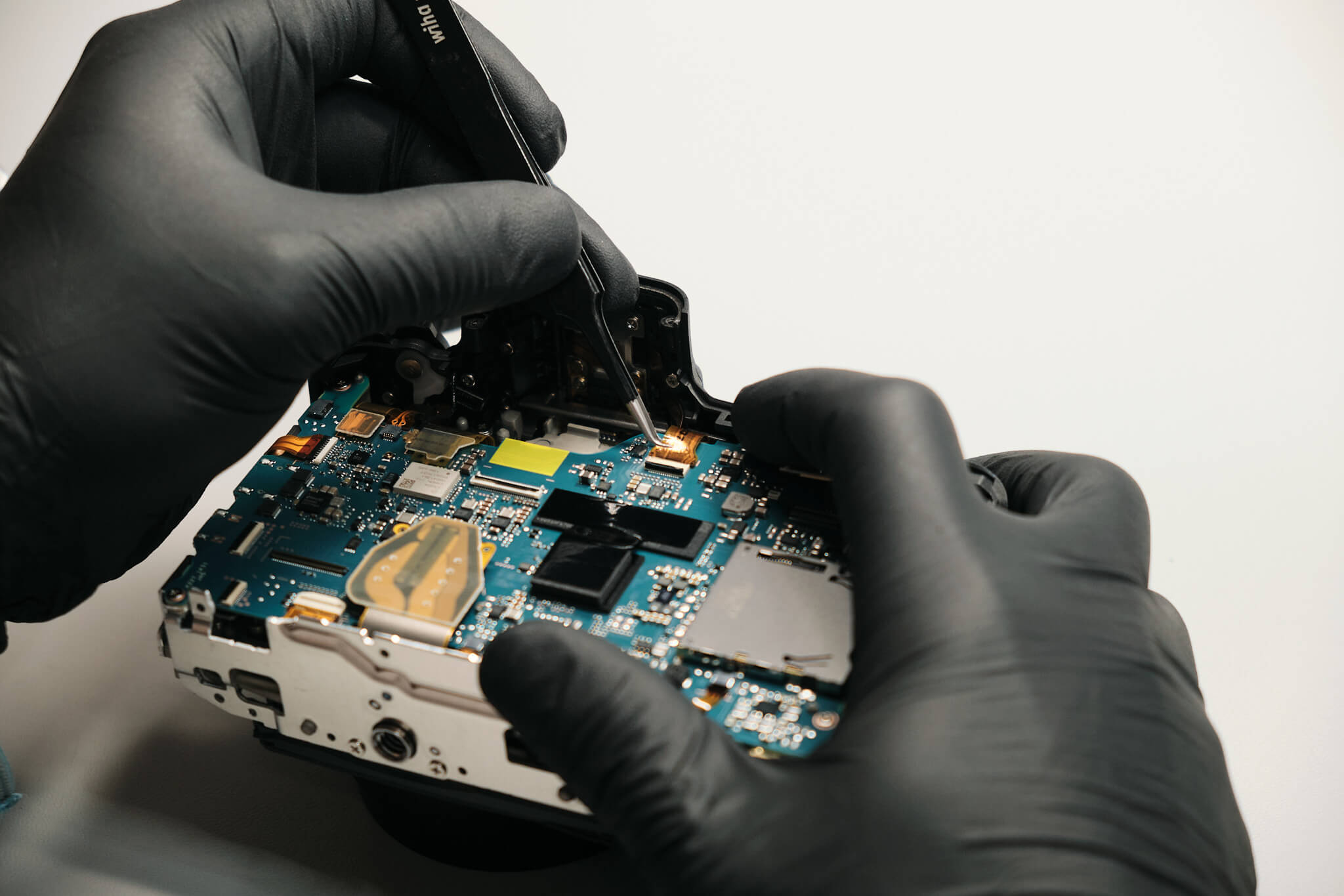
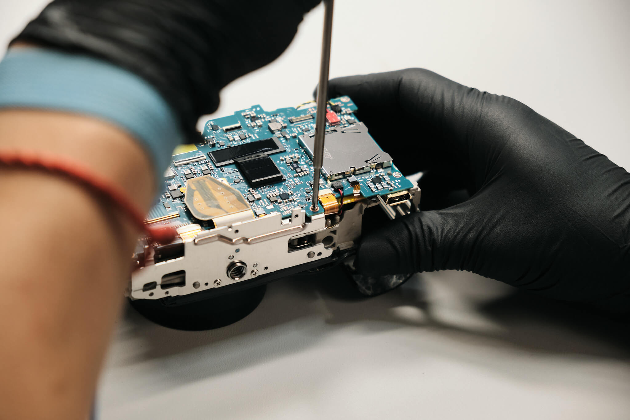
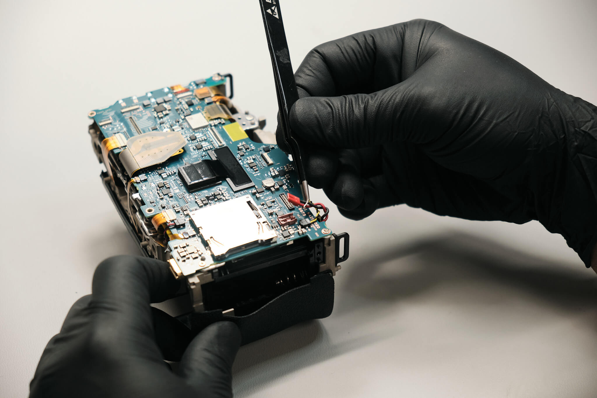
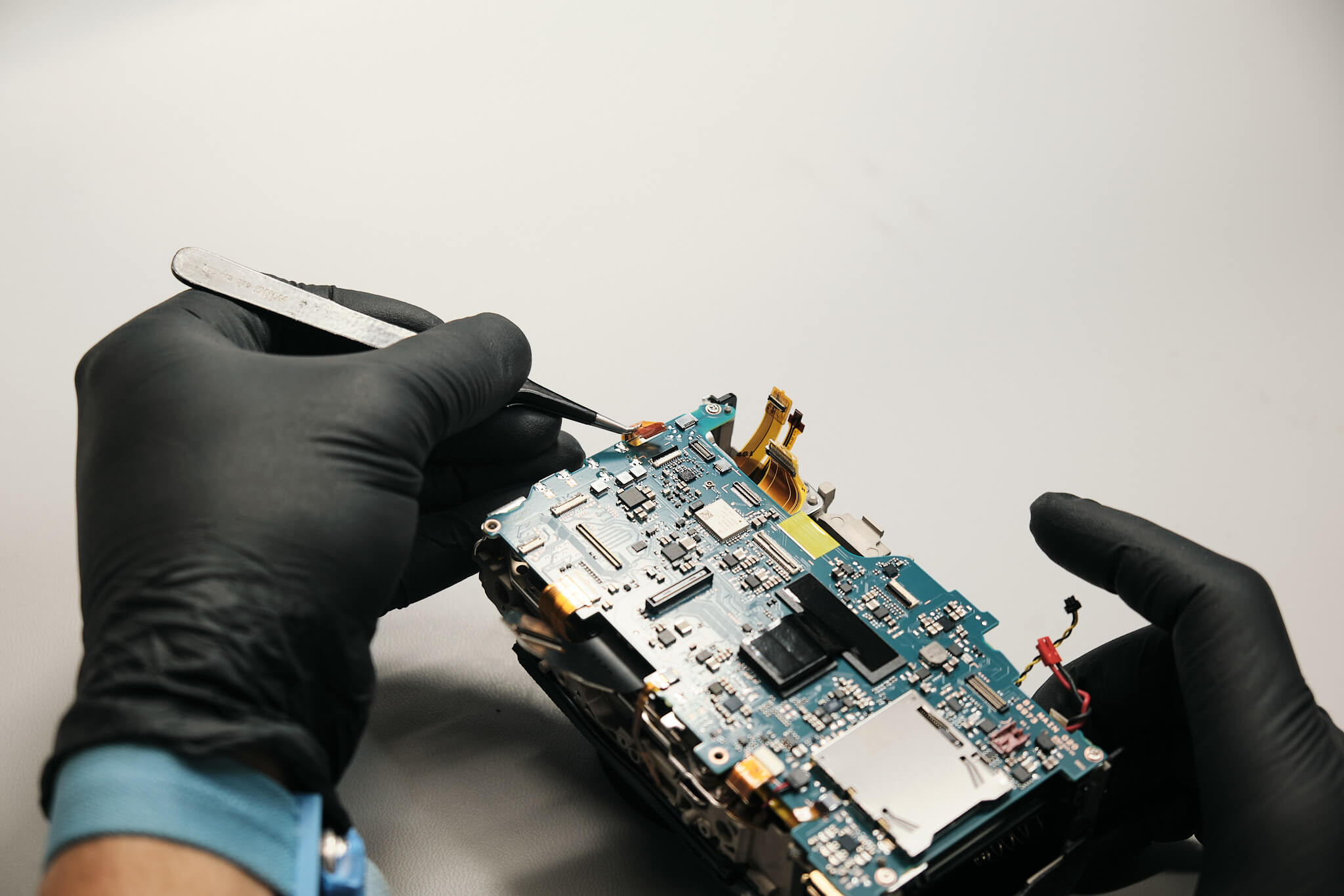
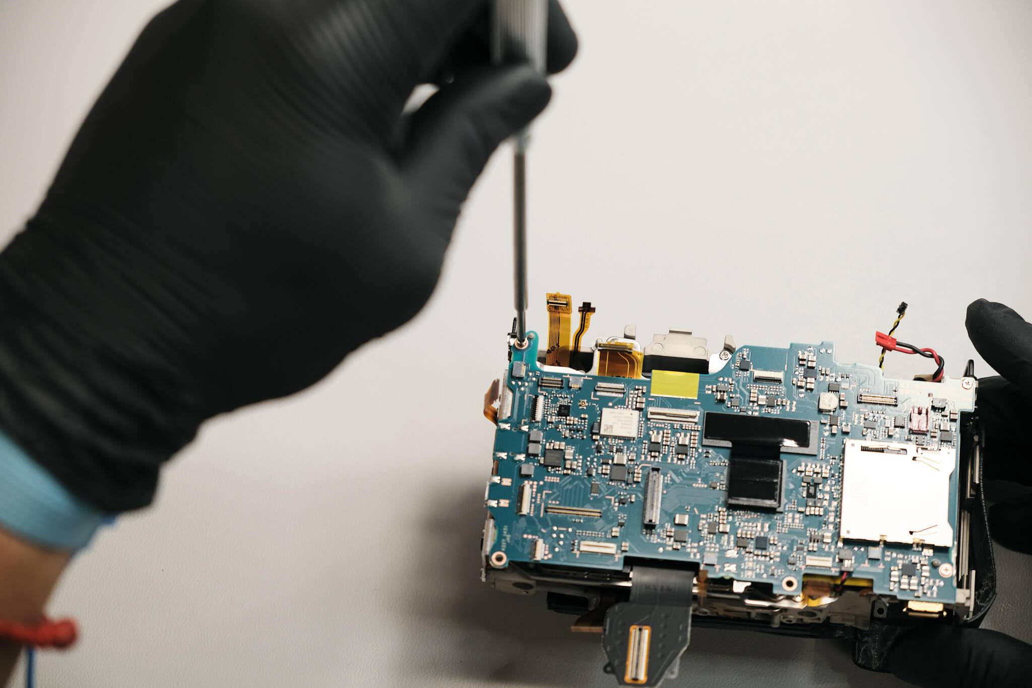
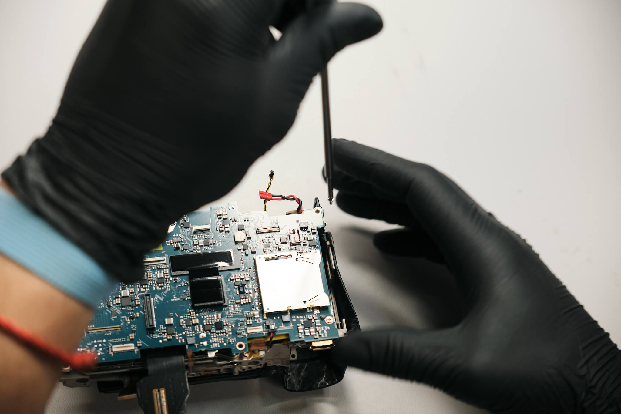
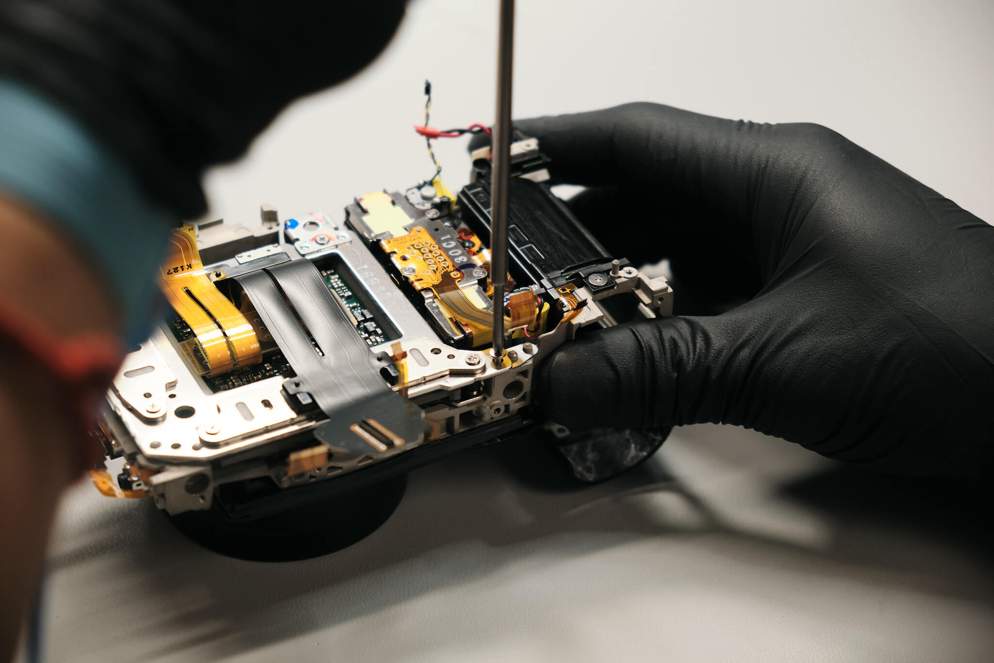
Time to take out the motherboard. First, we have to disconnect the remaining ribbons and cables.
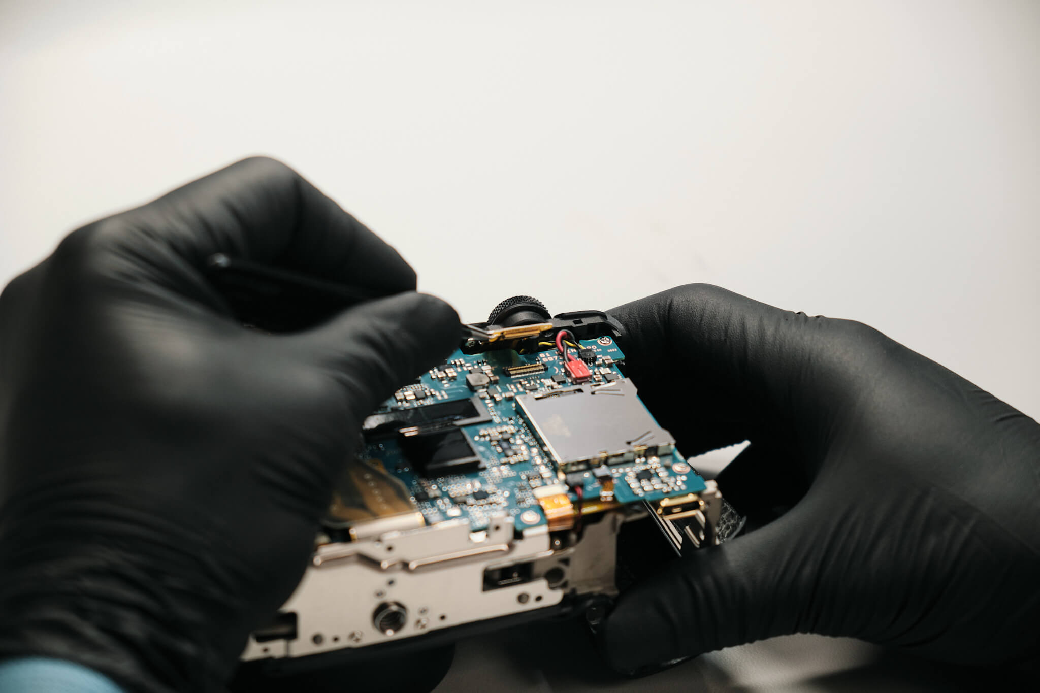
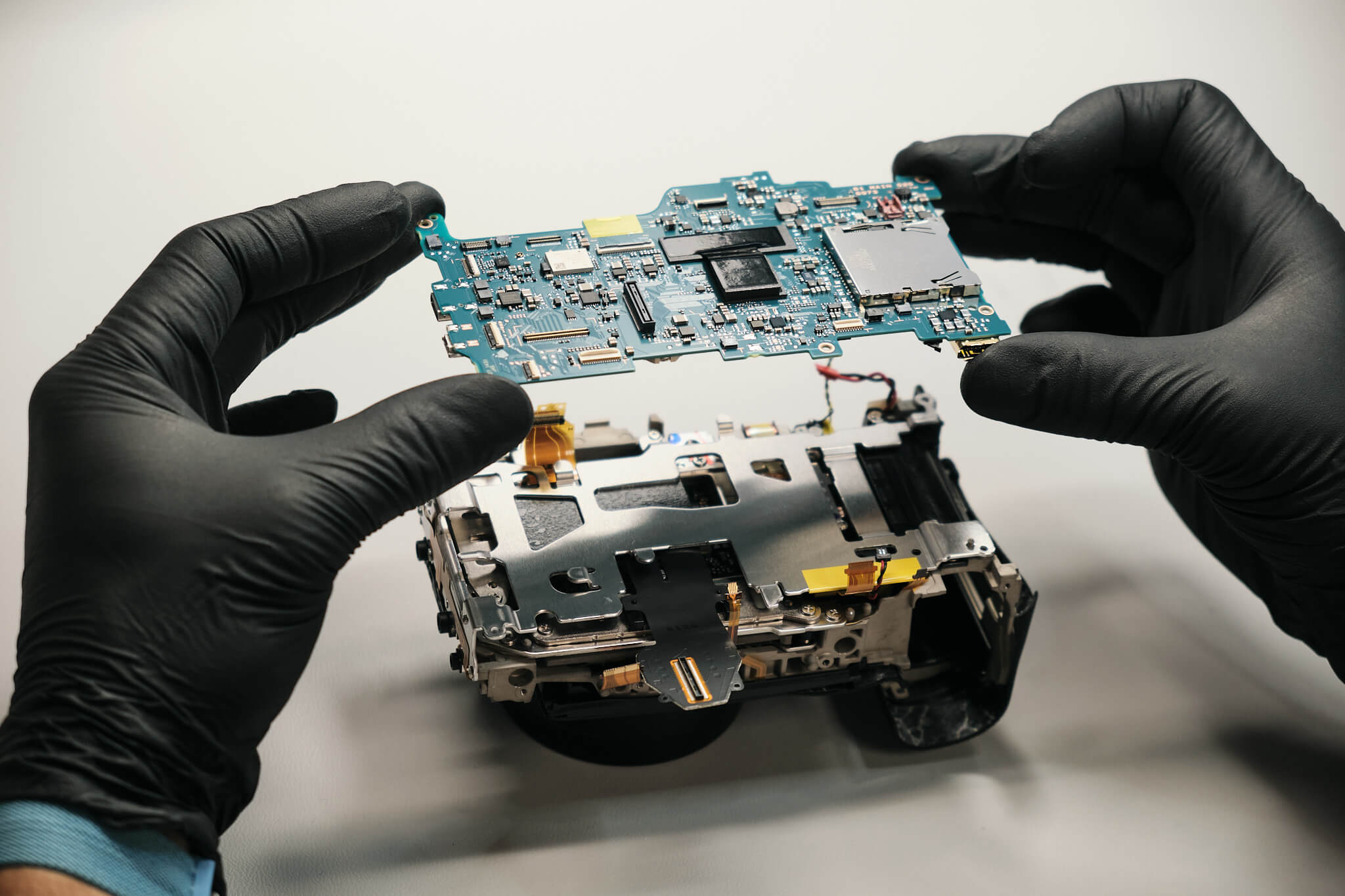
We unfasten three remaining screws to remove the motherboard from the camera body.
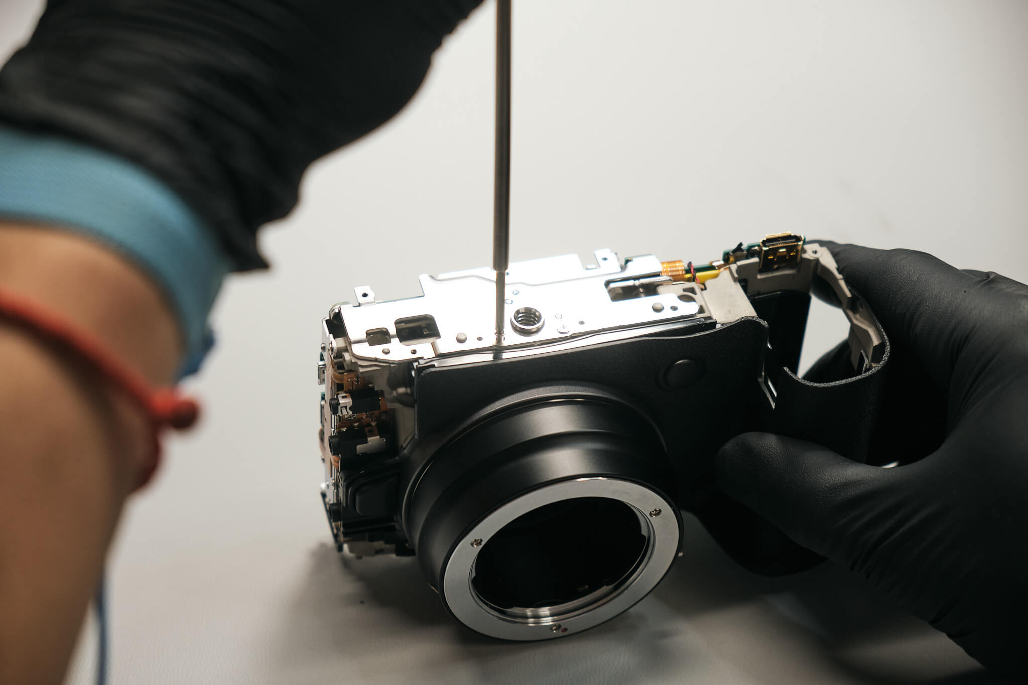
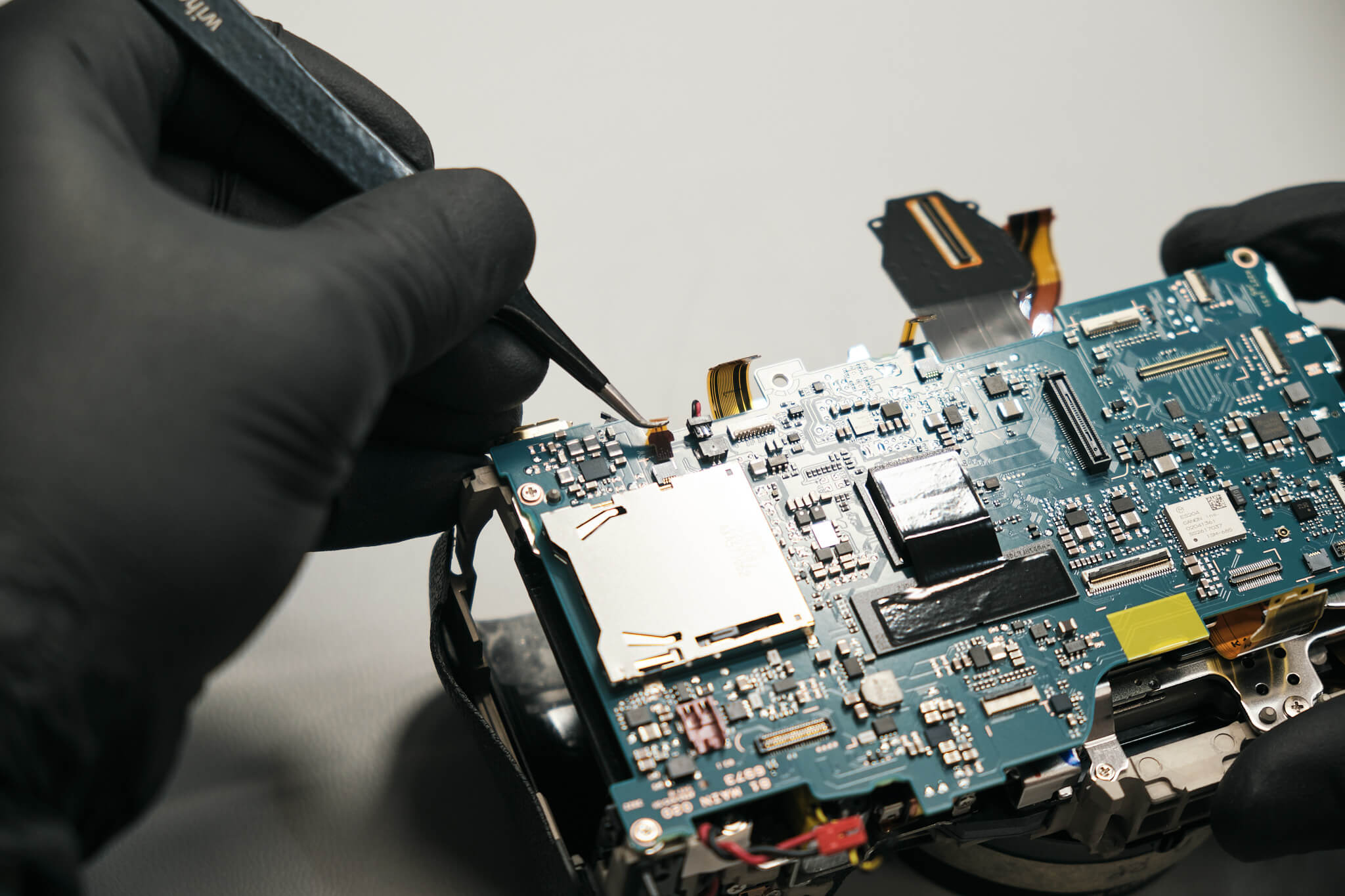
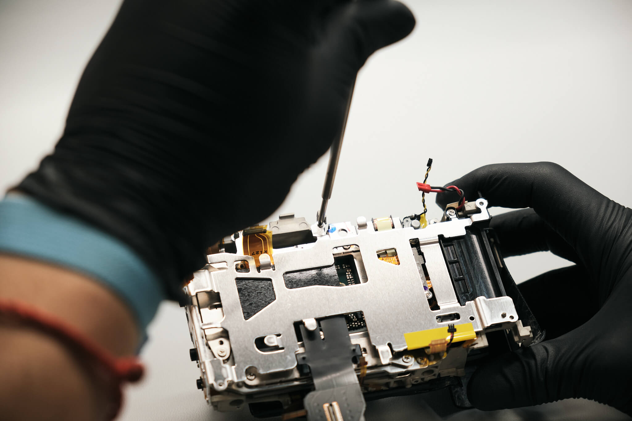
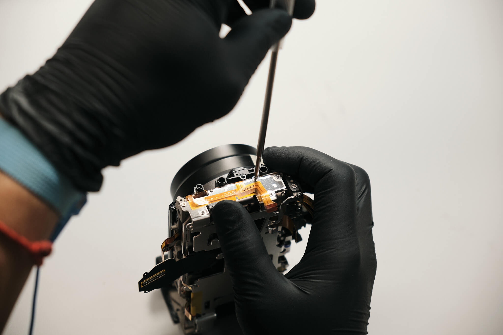
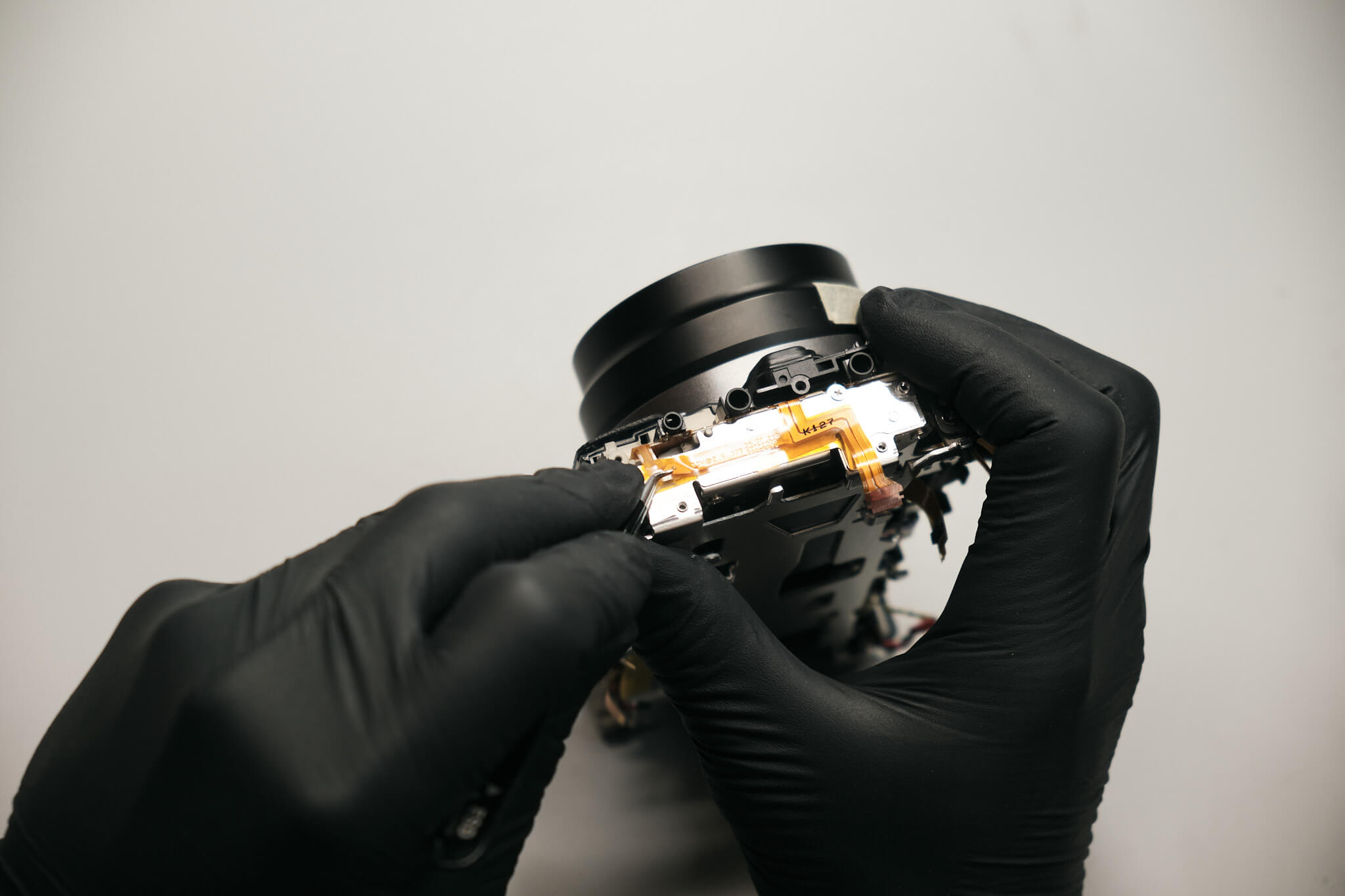
The circuit board bracket is held in place with four screws. Once those screws are removed, the terminal ribbon needs to be peeled off the bracket before it can be disconnected from the ports and the bracket can be fully removed.
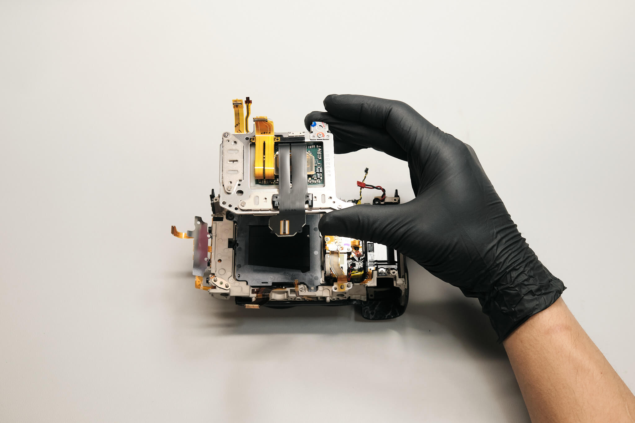
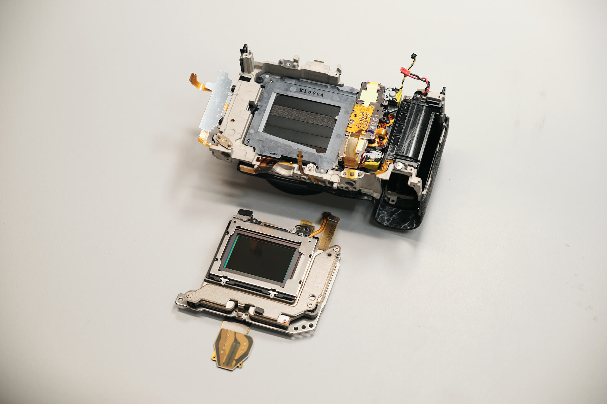
The sensor is fastened to the camera body with three screws. Canon uses shims and blue thread lock glue for the sensor screws.
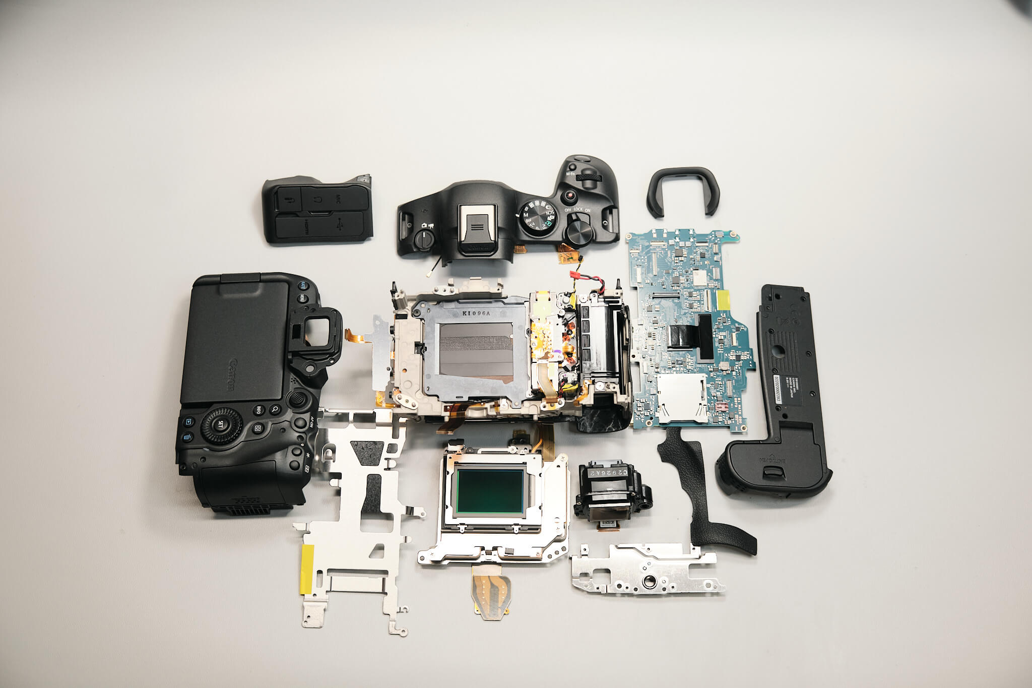
We found the Canon EOS R6 MK II was nearly identical to the original Canon EOS R6 camera in assembly. Nothing was different between the exterior design aside from several cosmetic changes and the format of the internal components. Nonetheless, the Canon EOS R6 MK II provides handy functions that surpass its predecessor.
Thanks for reading. If you’re interested in more camera disassembly and teardowns, we feature new disassemblies every month, so be sure to subscribe so you don’t miss them.
Table of content
Related Article
Product Spotlight
Comments
One Response
Great job, well done. I have a question regarding the viewfinder eyepiece glass, which I have just discovered is cracked. No idea how it happened but looking at your tear-down it looks like there’s a lot more to do than just removing the rubber eyecup to replace the broken glass! Am I looking at leaving it into a repair centre?