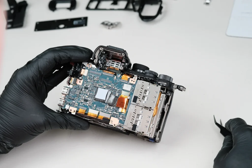
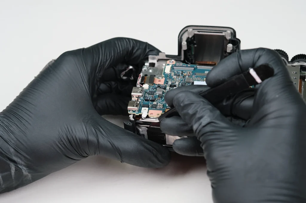
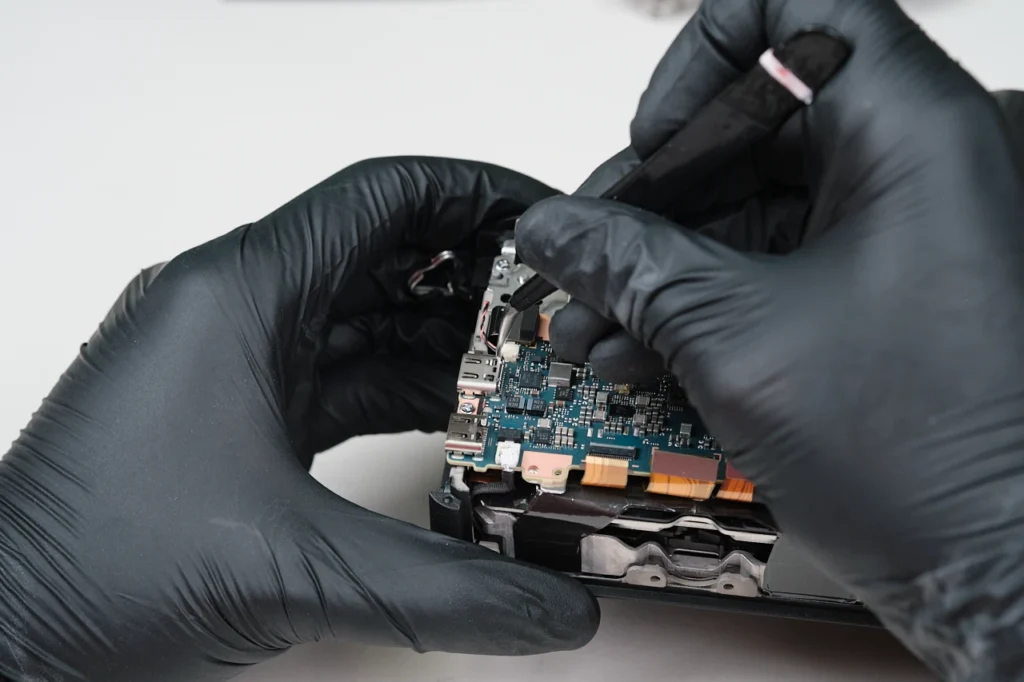
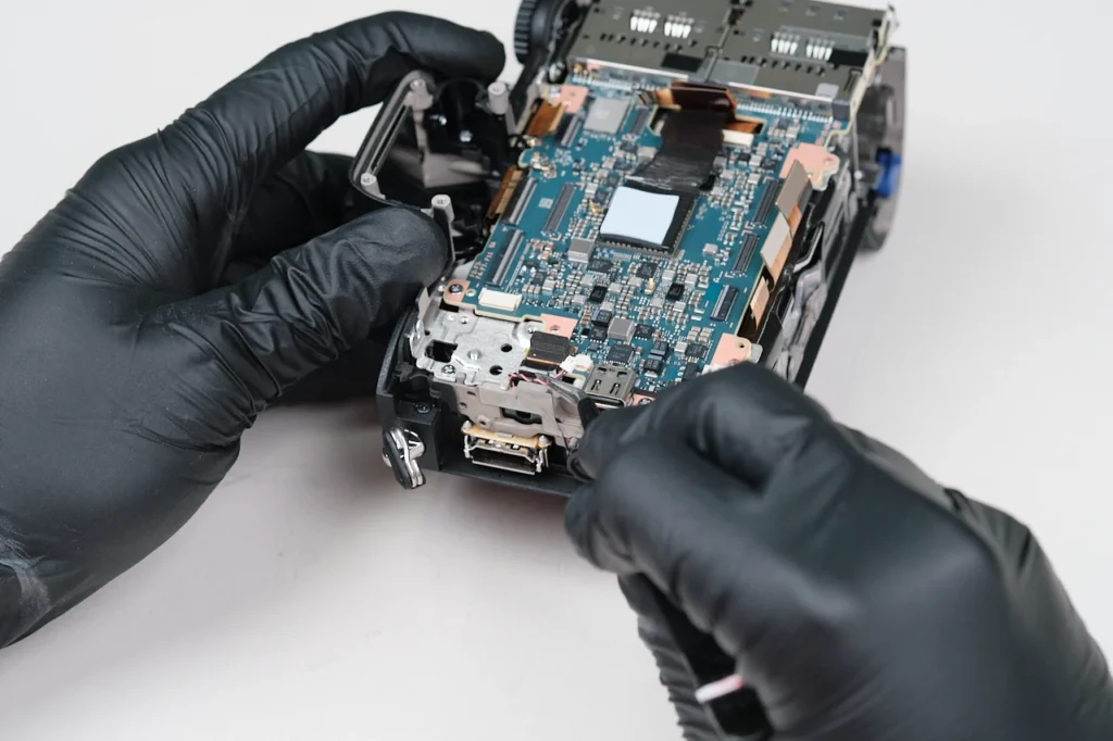
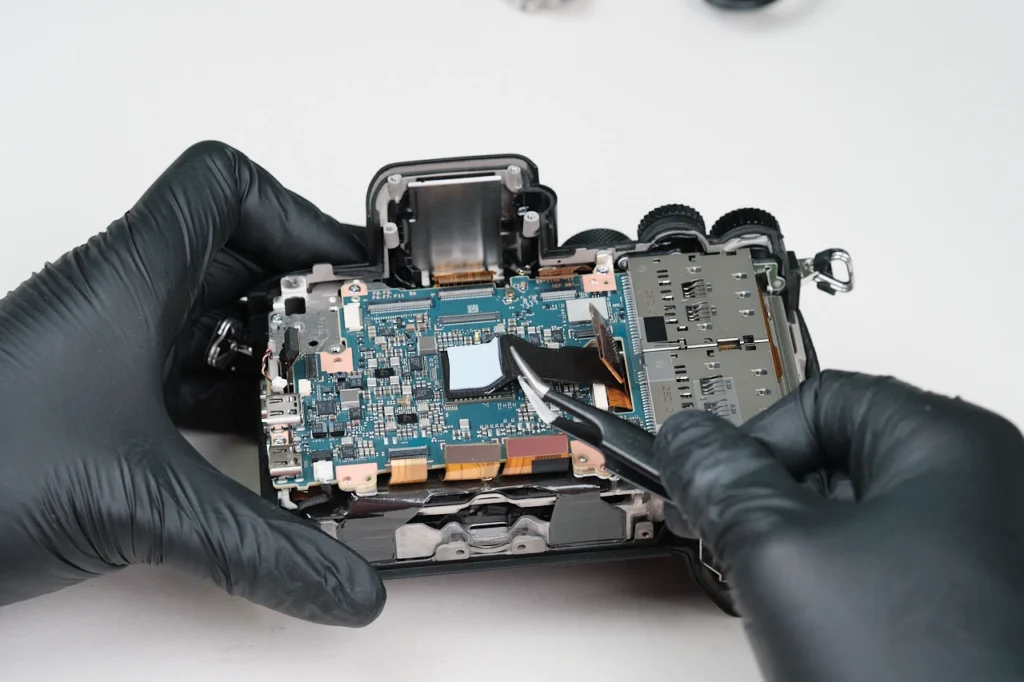
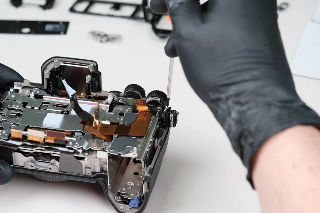
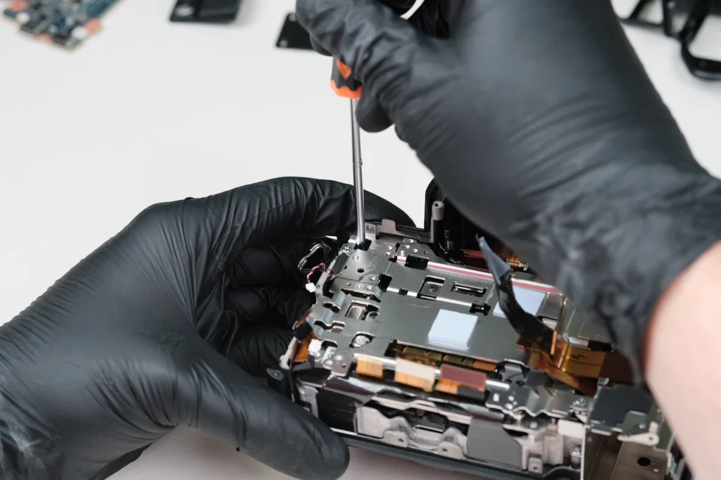
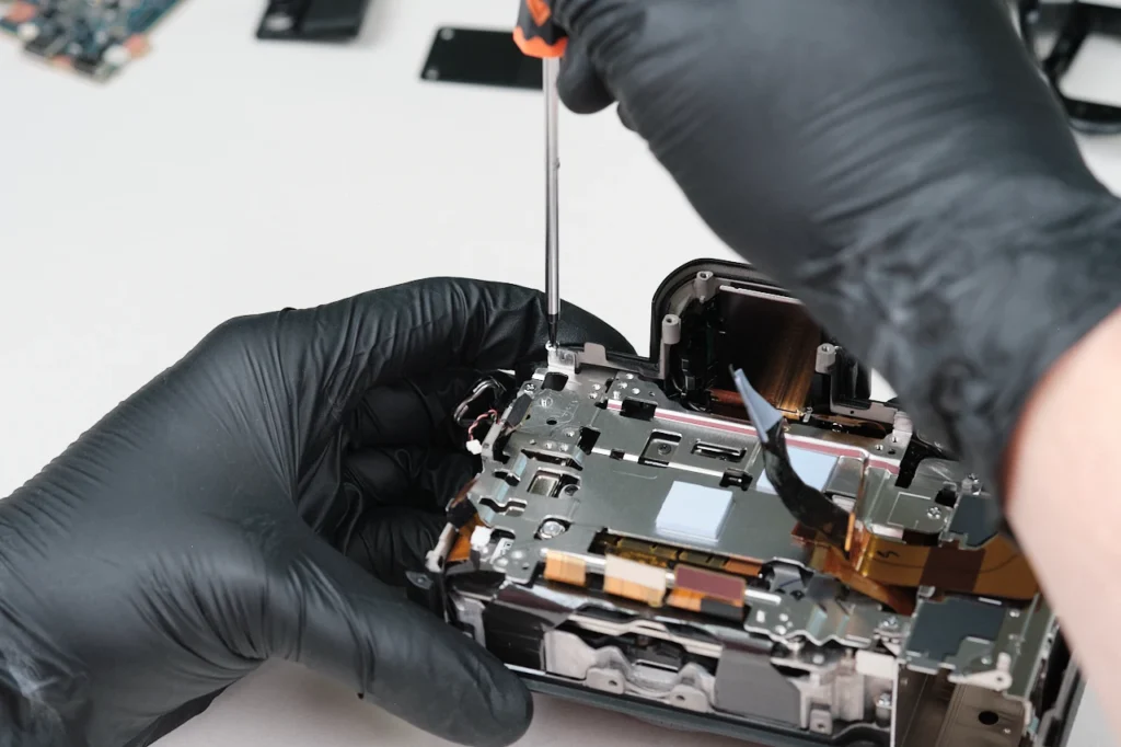
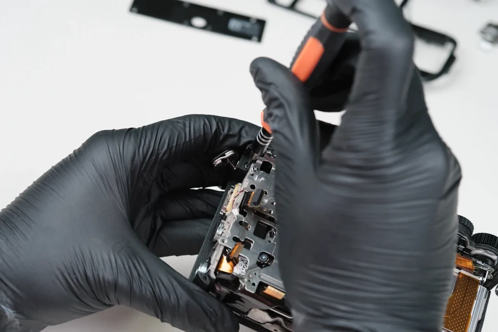
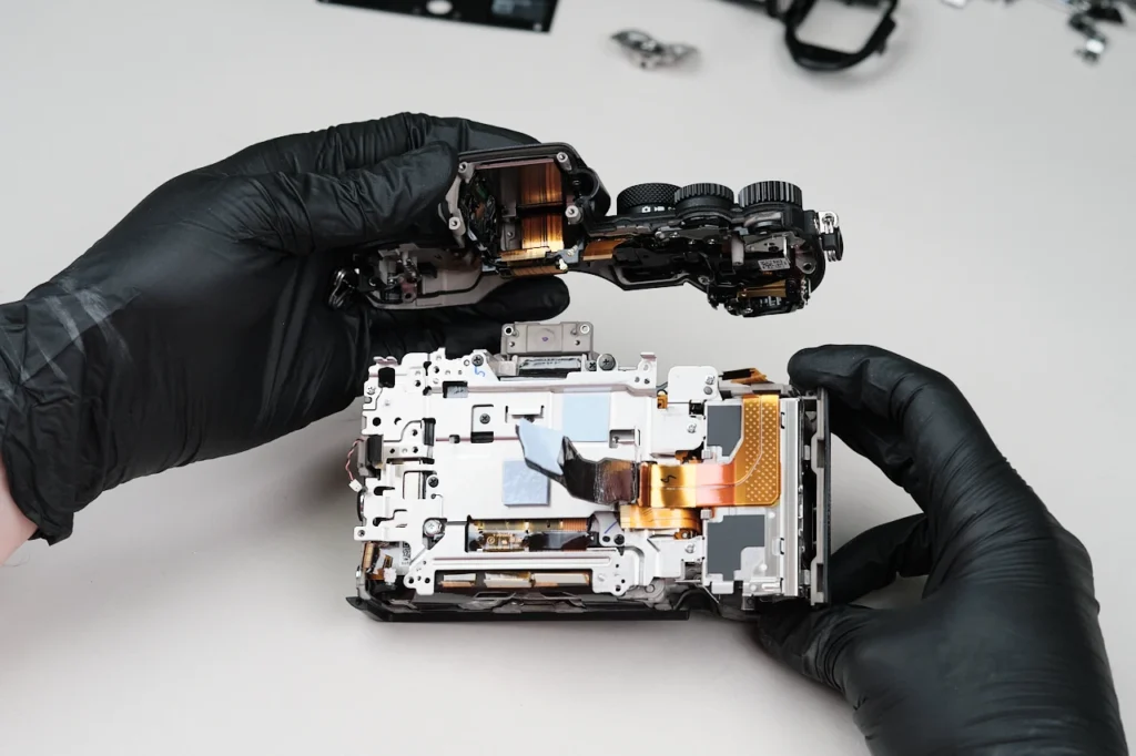
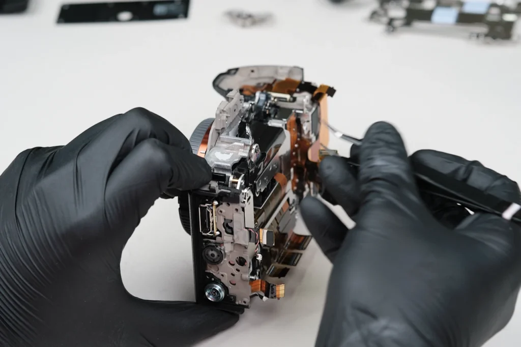
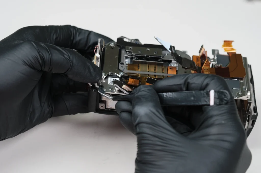
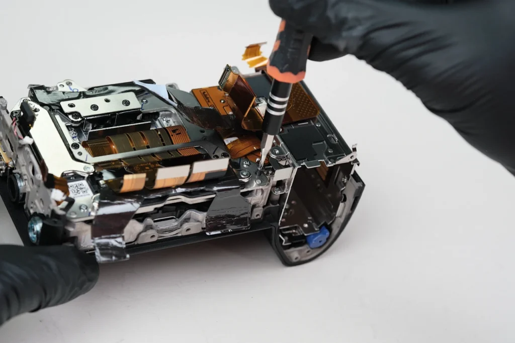
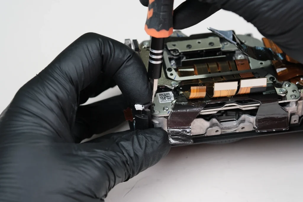
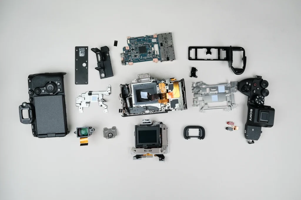
The Sony A7RVI is the latest offering from Sony’s mirrorless camera lineup, succeeding the highly regarded A7RV. Online opinion on the camera is polarizing as some shooters love it, while others are critical of the marginal improvements it brings. We’ve previously torn down many cameras from the A7R line including the Sony A7RV, Sony A7RIV, and Sony A7RIII, so let’s see how this one compares to its predecessors.
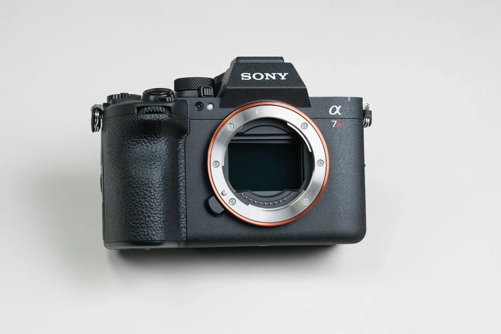
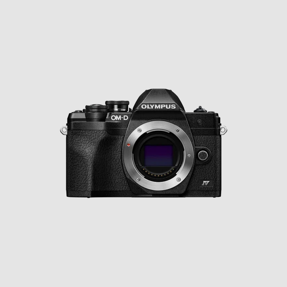
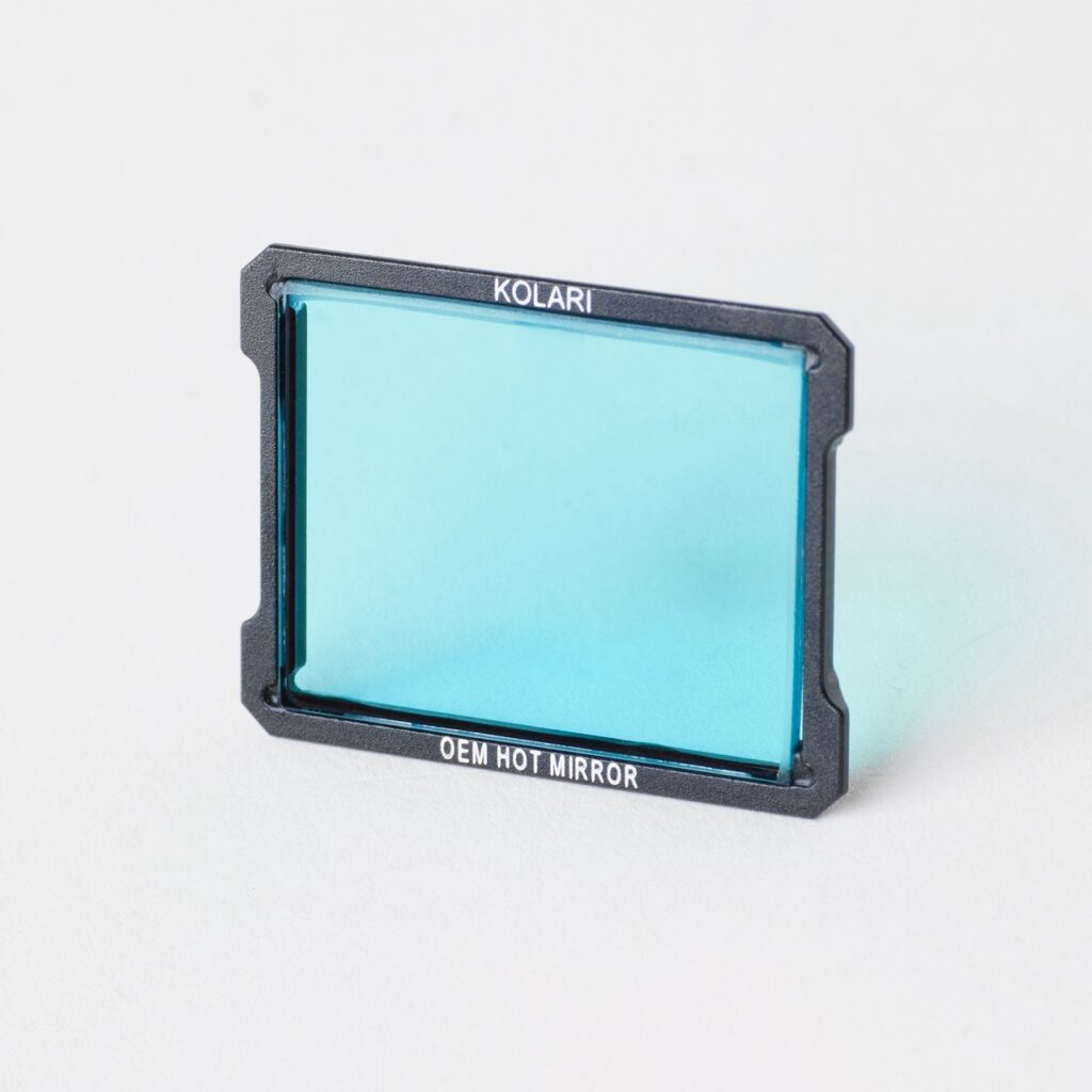
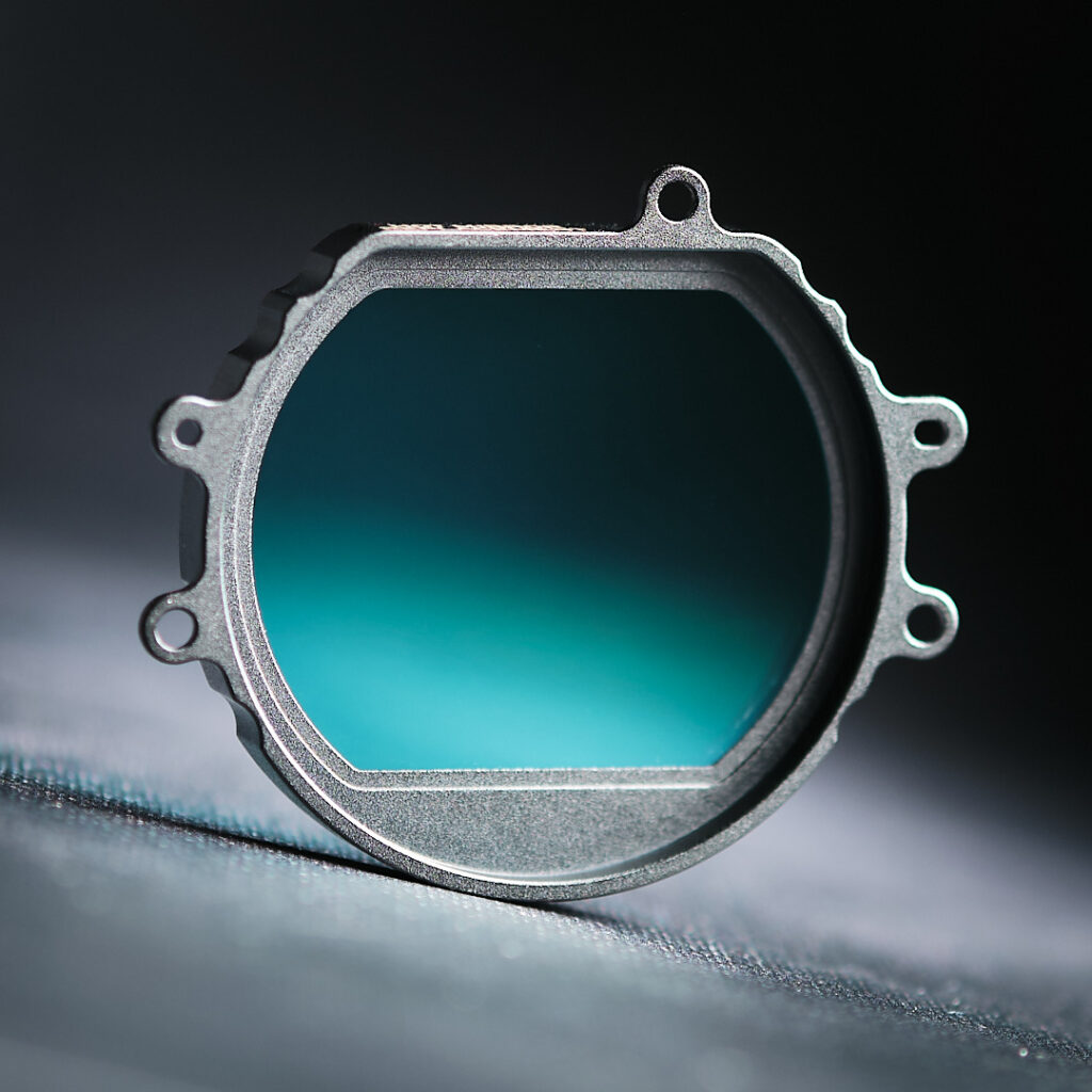
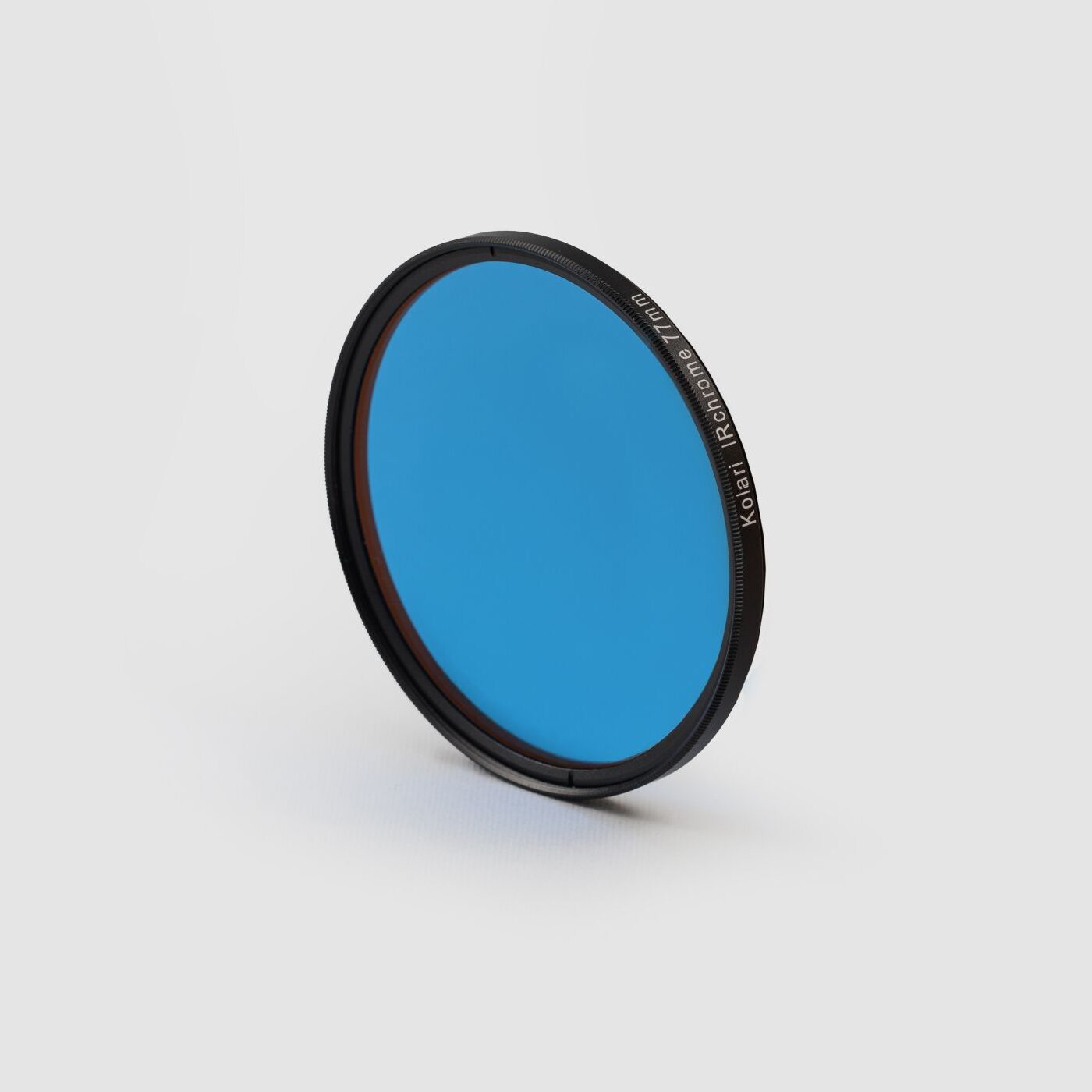
The Sony A7R VI features a different interior mount from its predecessors. You can see in the photo above that the upper section of the inner mount has a ridge, meaning this camera is not currently compatible with our magnetic clip-in filters for Sony E-mount. However, this camera is capable of being converted to full-spectrum through our Sony A7R VI Full Spectrum Conversion Service.
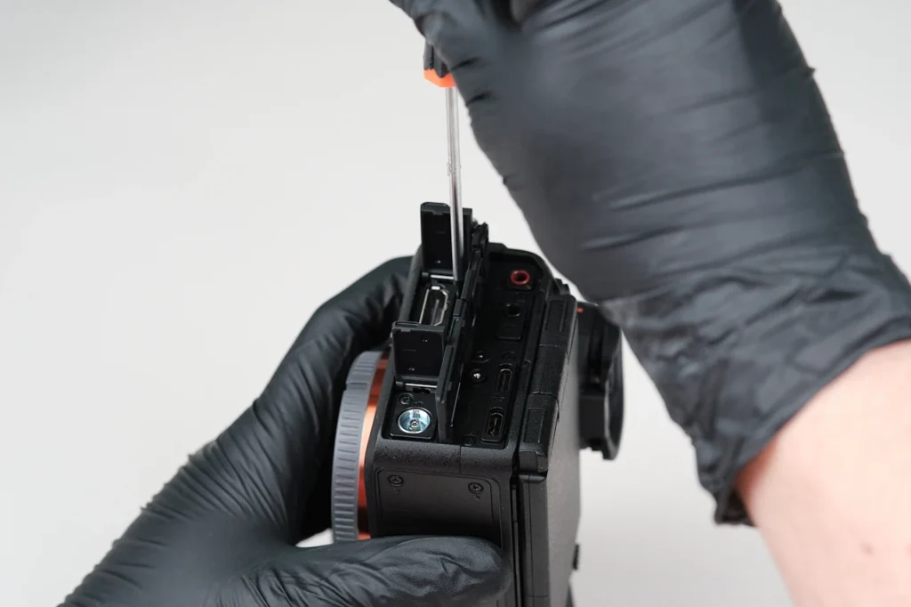
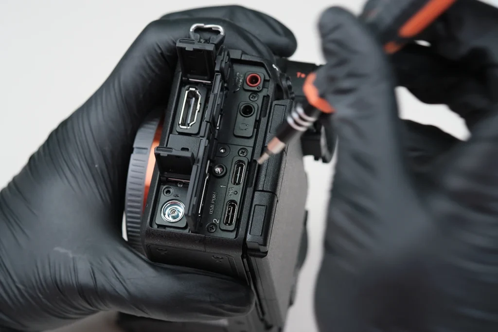
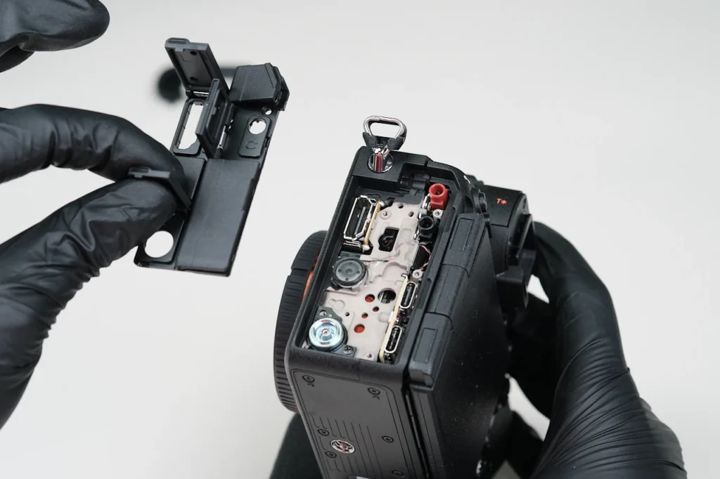
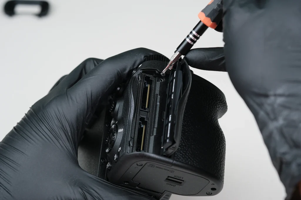
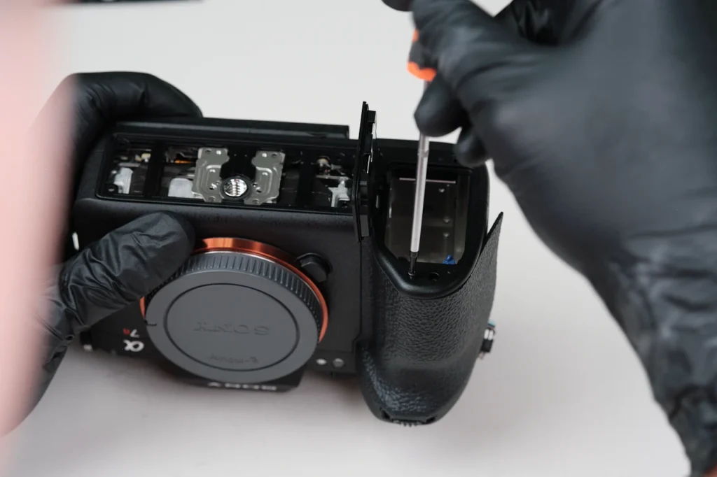
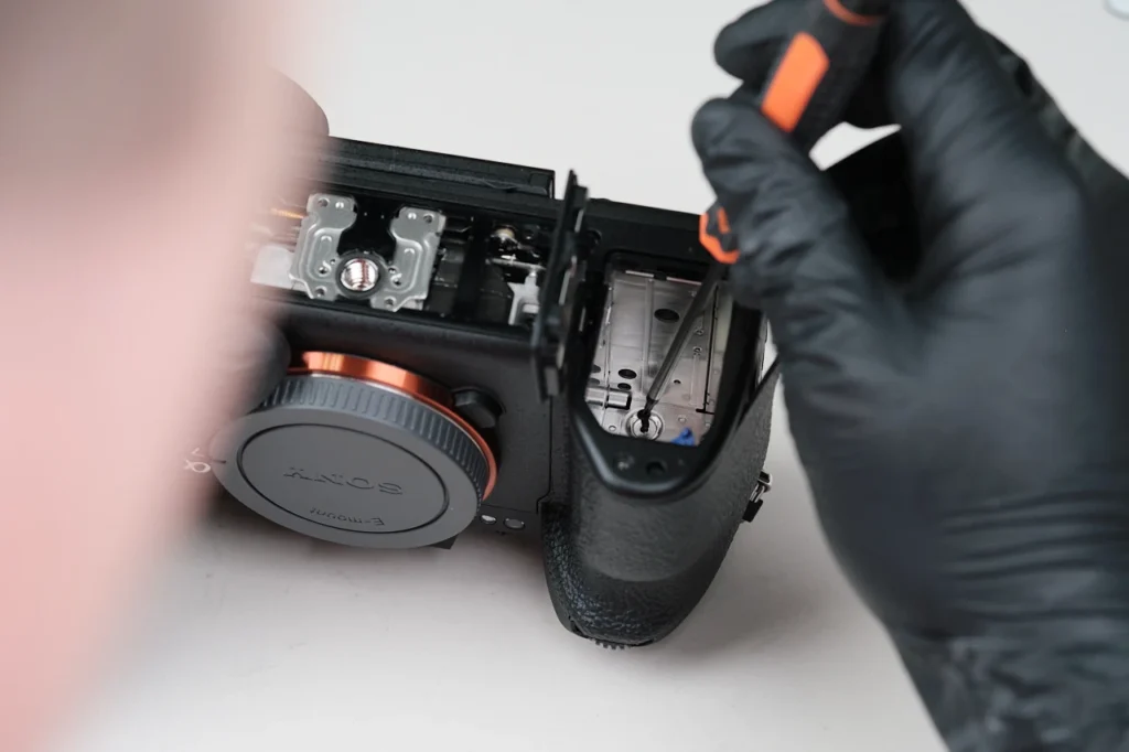
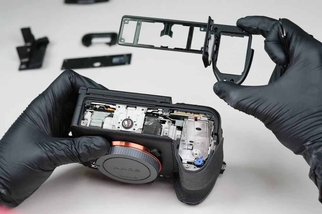
Although we normally start with removing the baseplate of the camera, we opted to remove the port side cover first. We removed five screws underneath the panel covers.
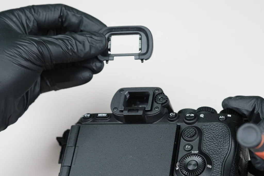
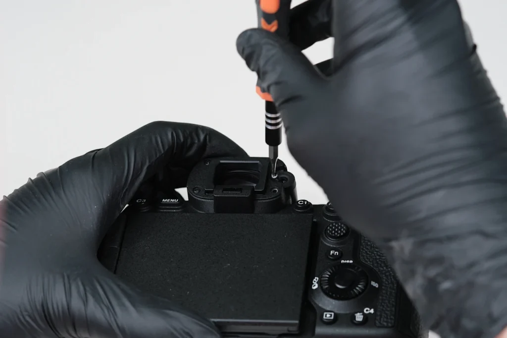
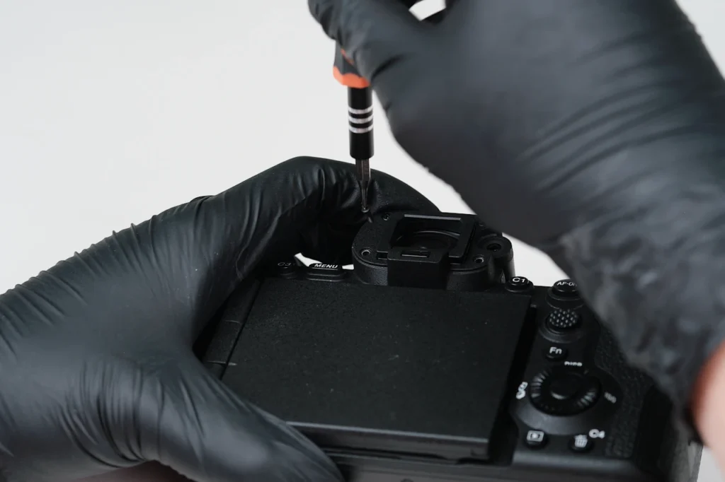
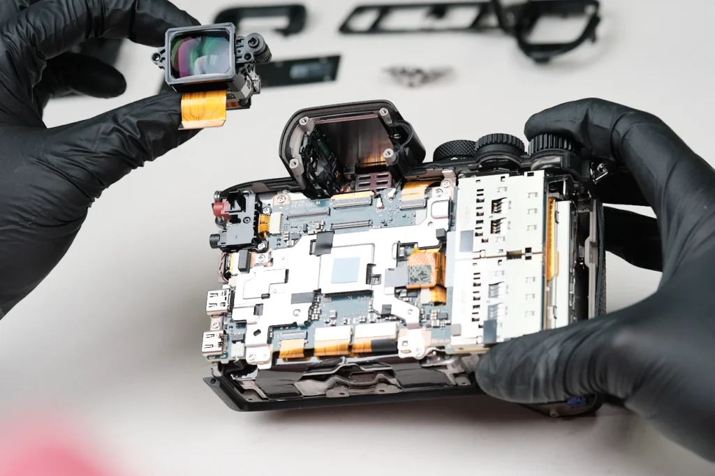
Beneath the eyecup, the EVF assembly is held down by four screws. The diopter is held in place only by a single screw.
There’s only one screw beneath the card slot cover.
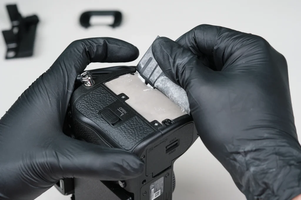
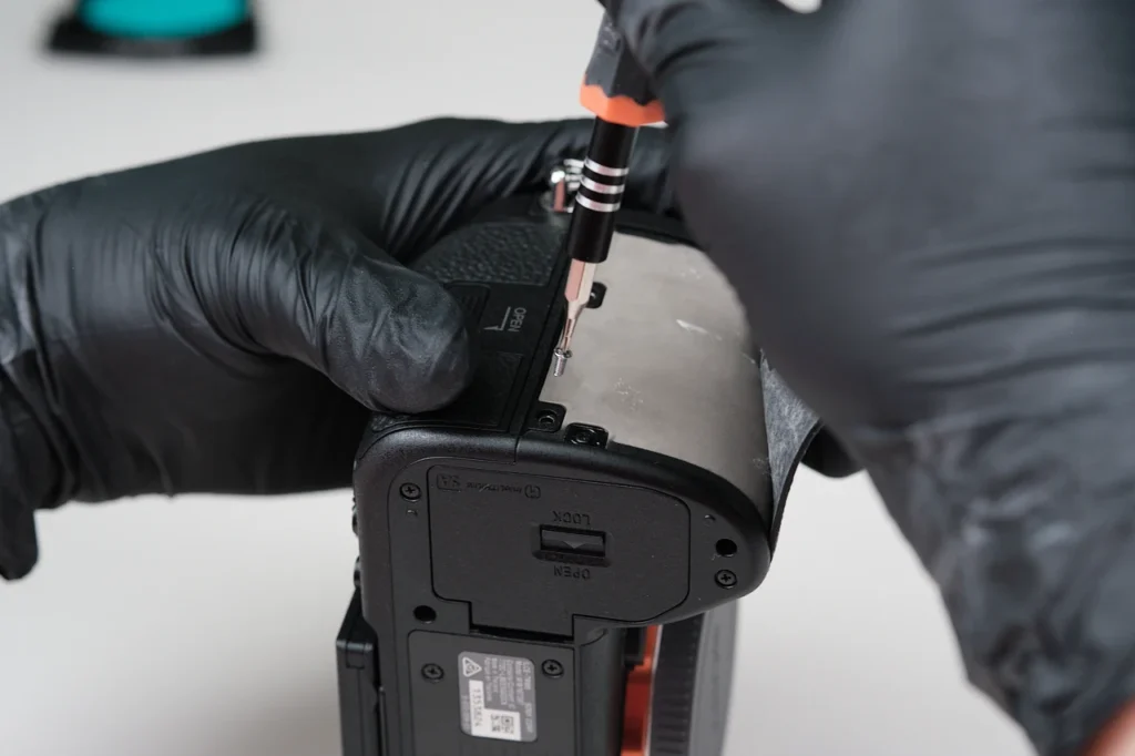
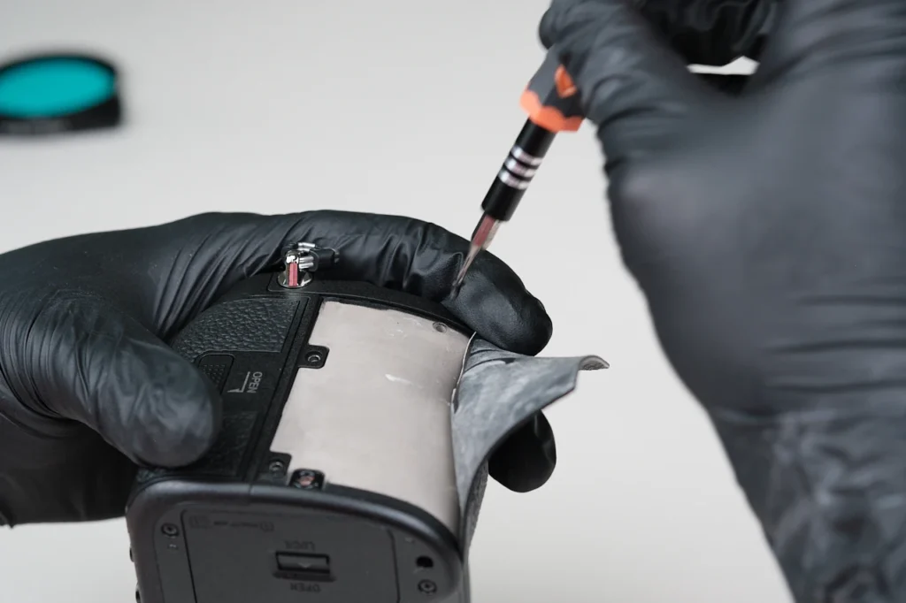
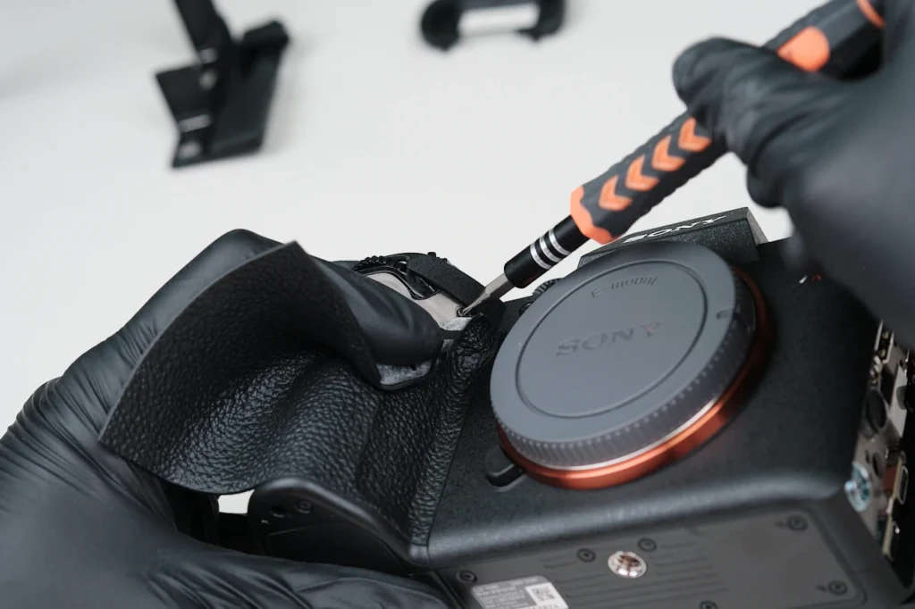
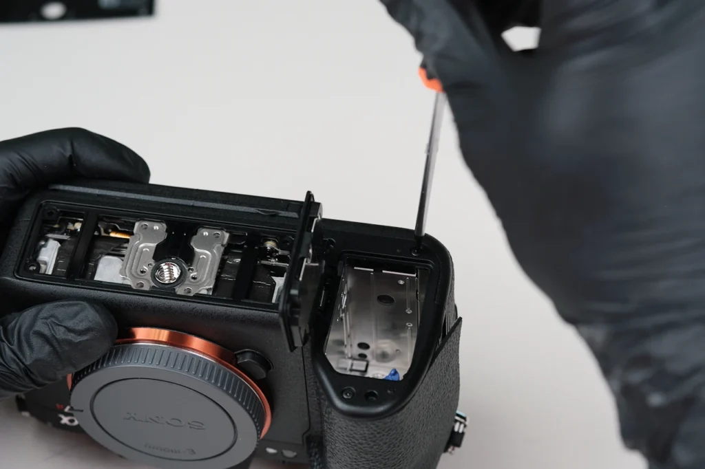
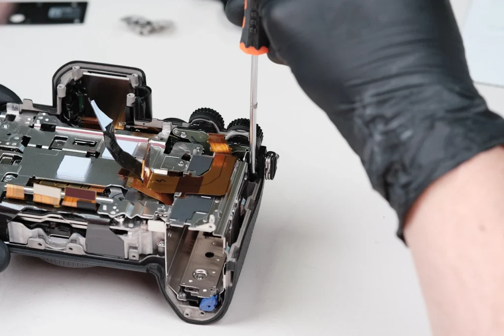
Although there may not be visible screws surrounding the body, they are most often found beneath the leather cover of a camera. There were five screws all around the handle side of the camera.
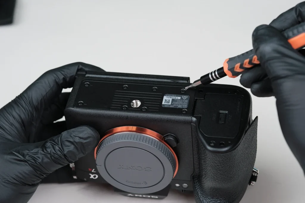
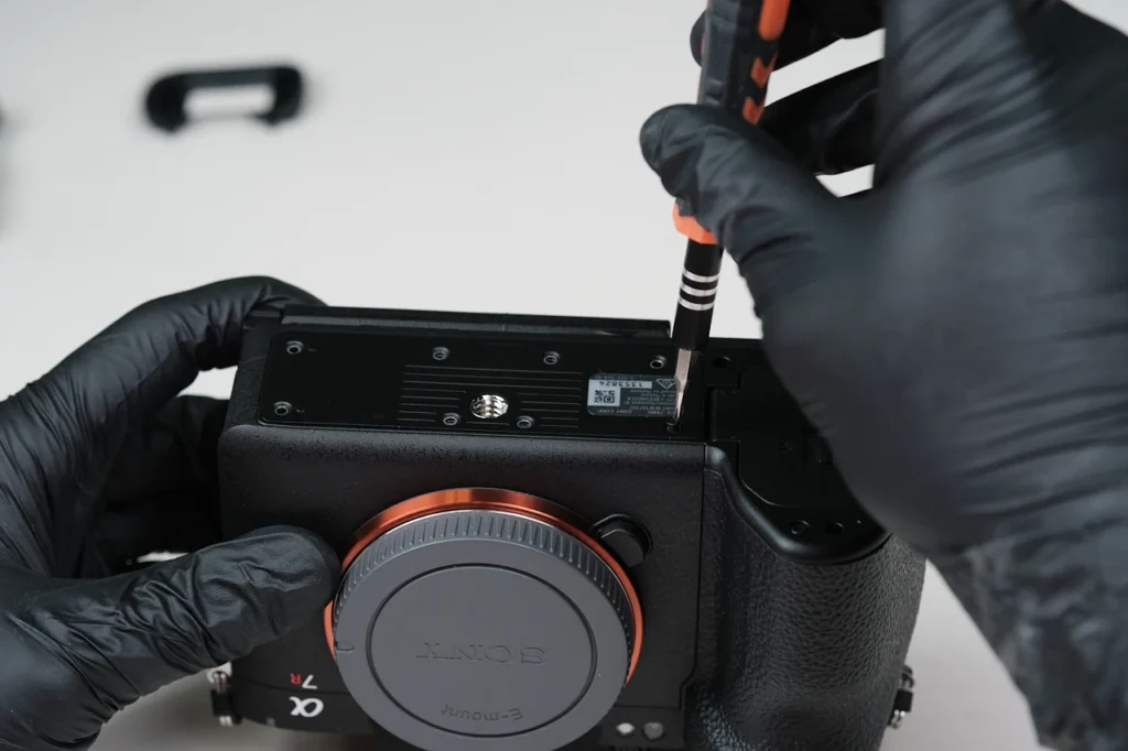
Eight screws secured the baseplate.
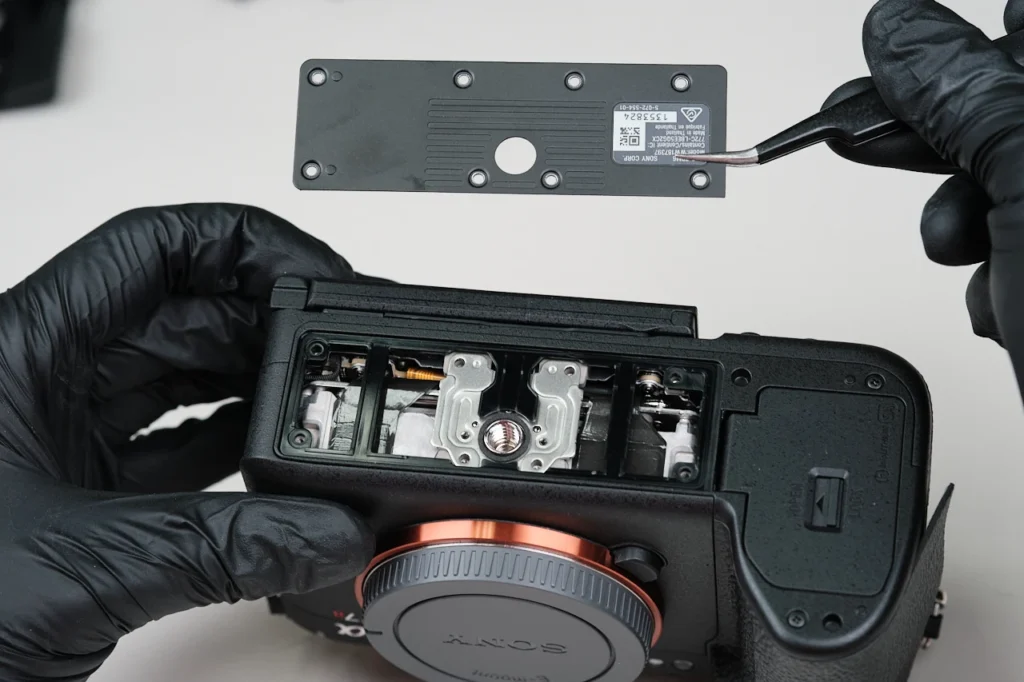
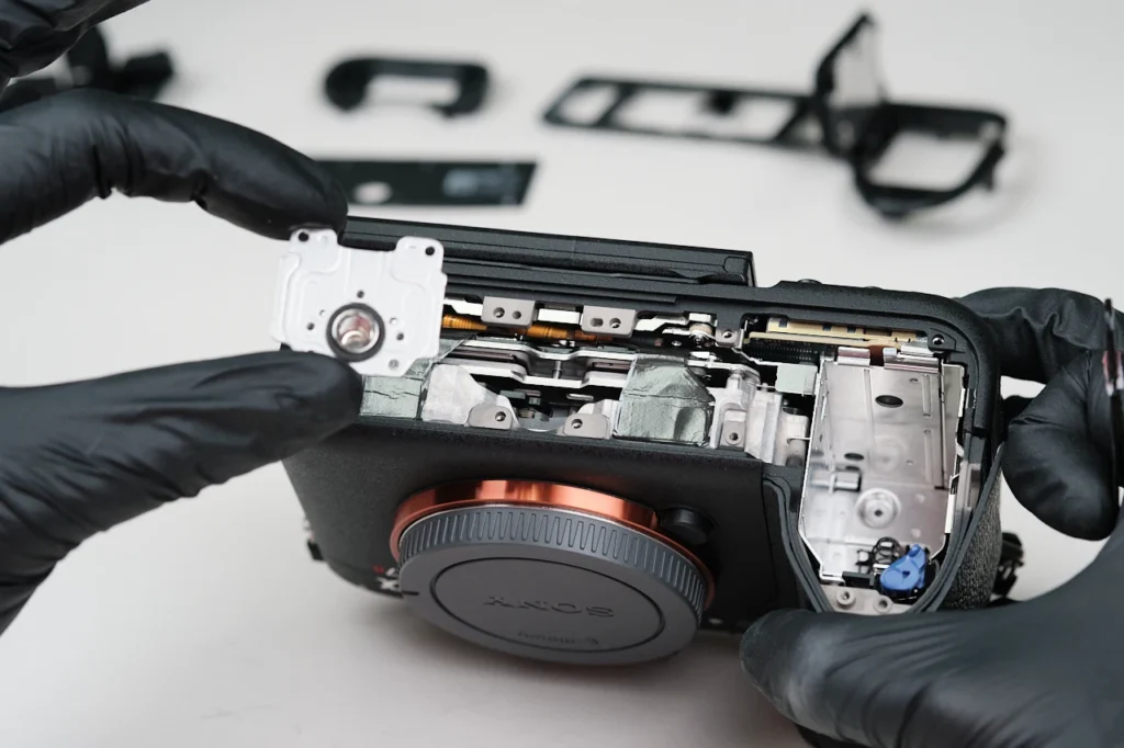
Several screws surrounding the perimeter of the battery compartment of the baseplate, and three screws within the interior of the compartment itself. We were able to remove the entirety of the baseplate assembly now. The screw mount piece is also removable at this point.
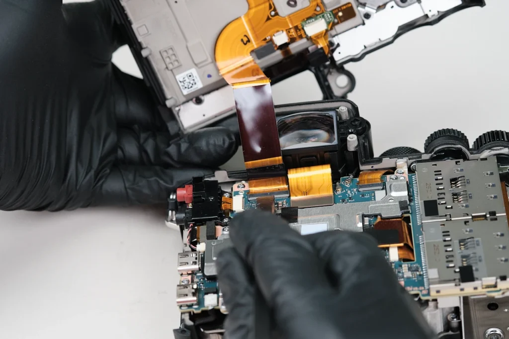
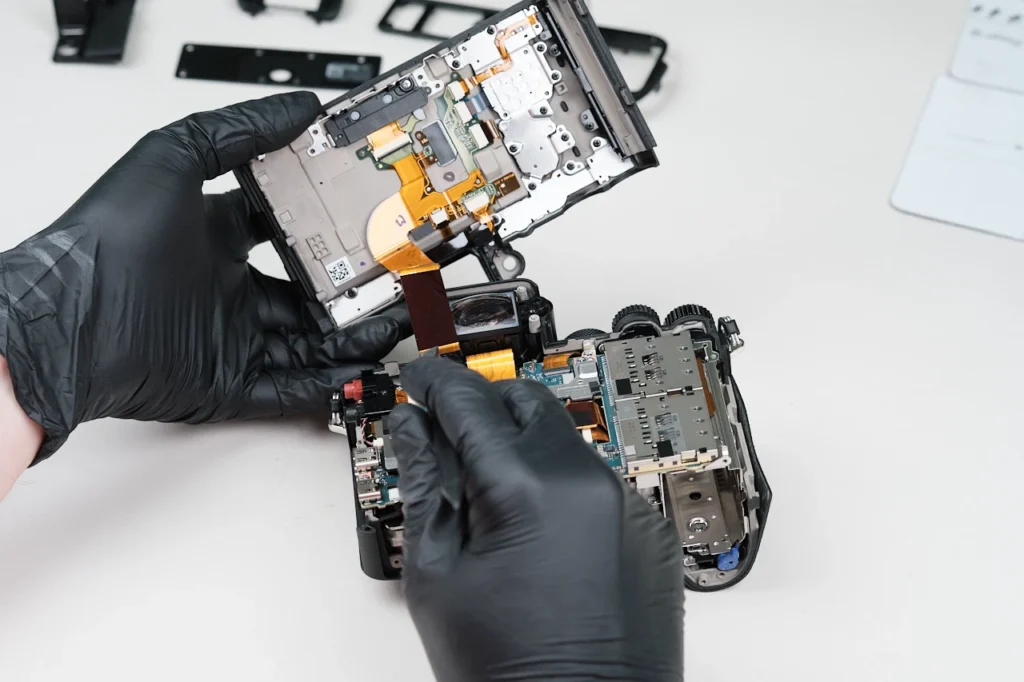
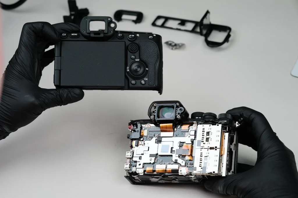
One large ribbon cable attaches the camera’s backplate to the circuitboard. Detaching this allows full access to the interior.
The EVF mechanism is attached via one ribbon cable.
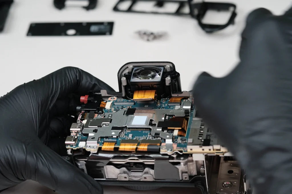
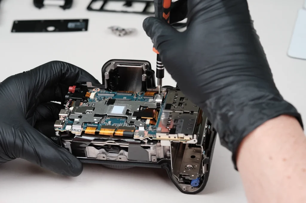
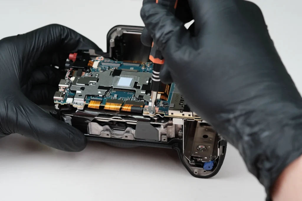
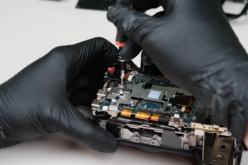
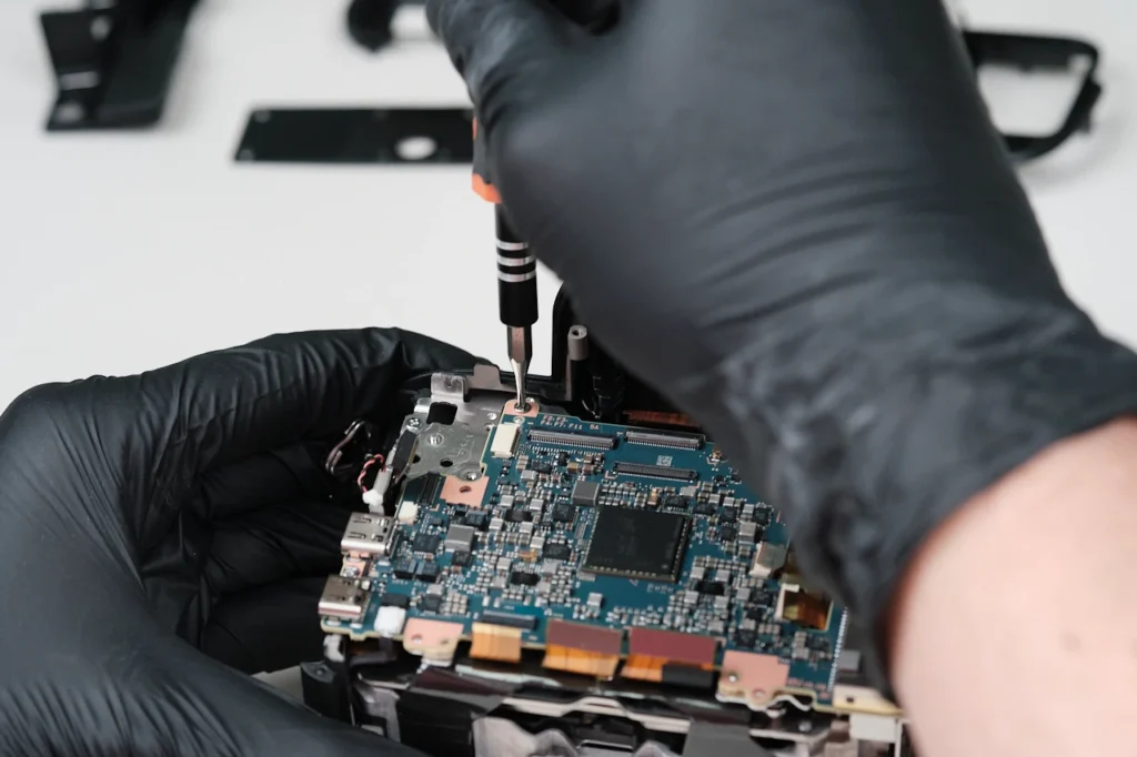
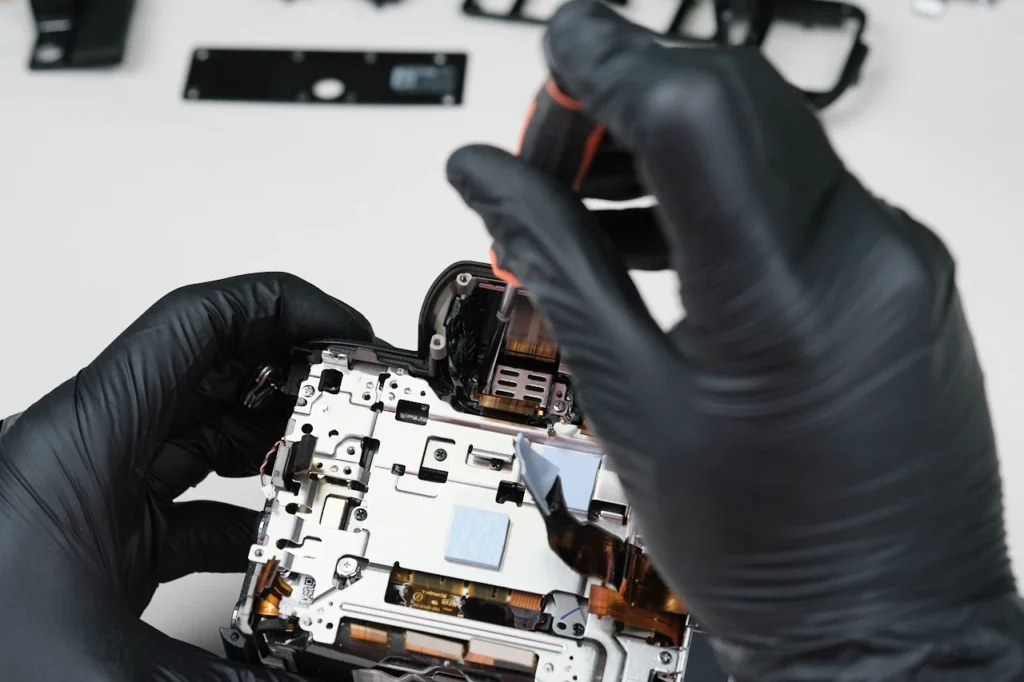
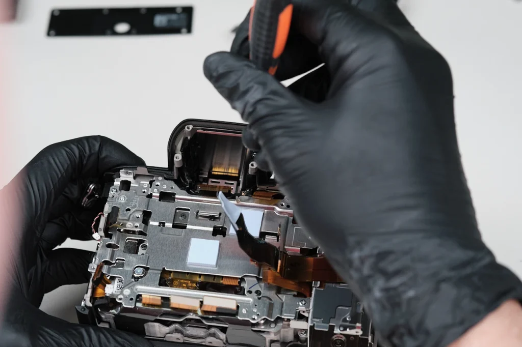
Four screws were removed around the perimeter of the RF shield bracket.
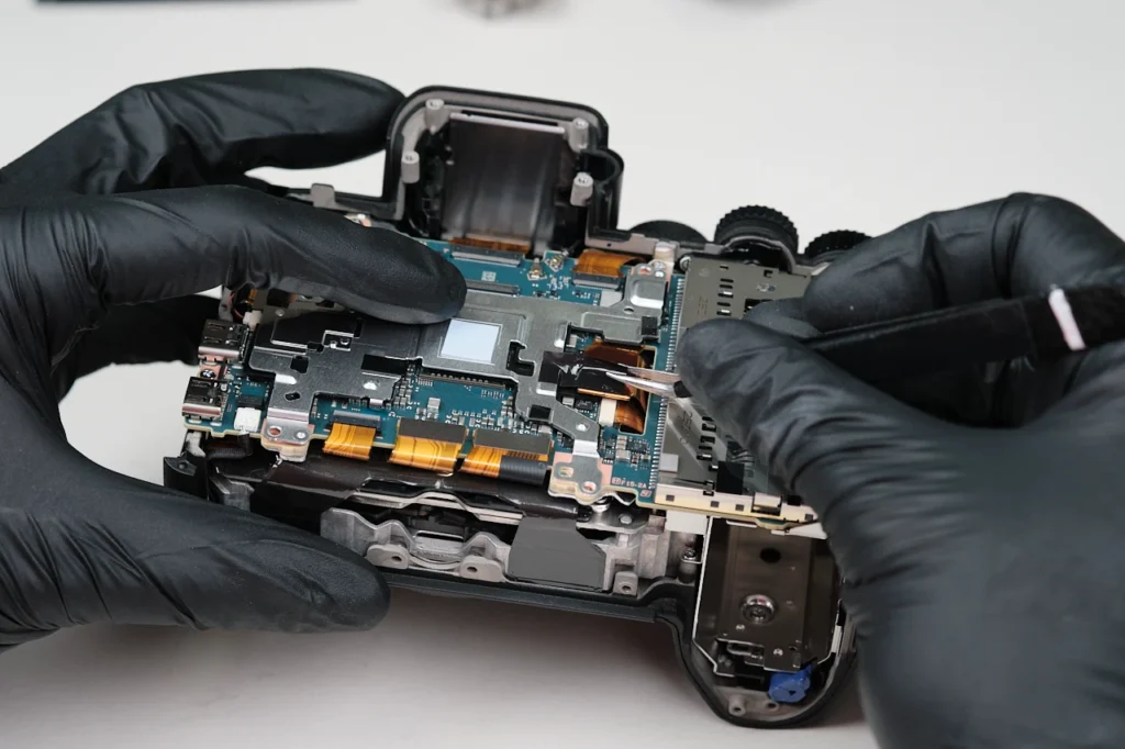
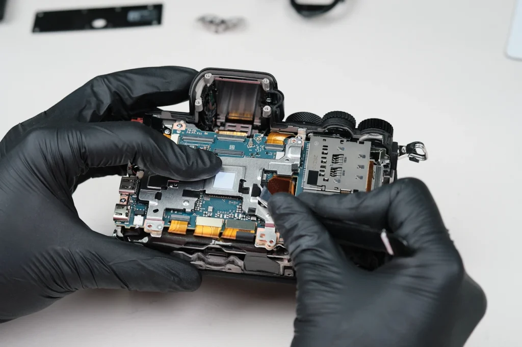
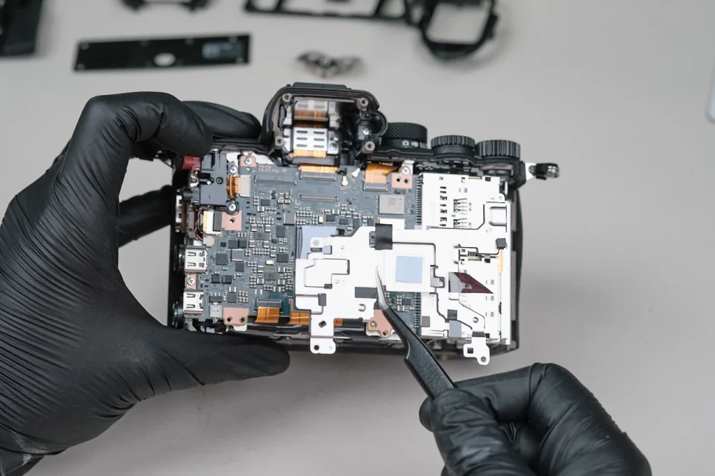
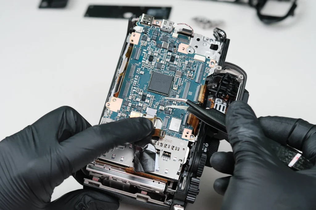
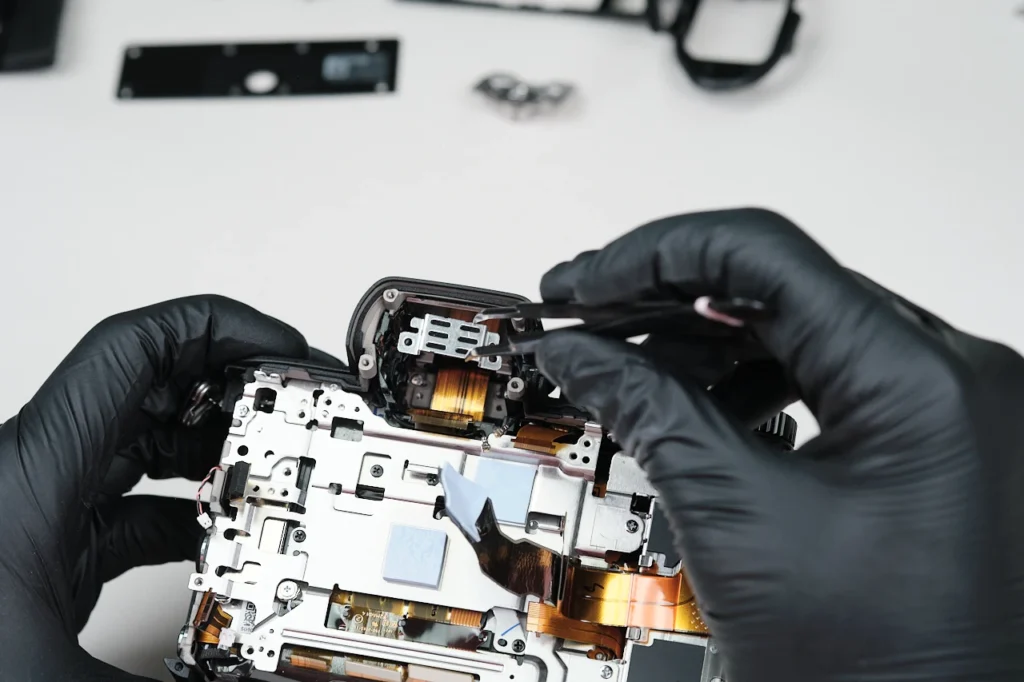
There was one heat transfer tape connected to the RF shield bracket, which required us to ring it through the bracket for full removal. We were then able to lift it away from the circuitboard.
The circuitboard
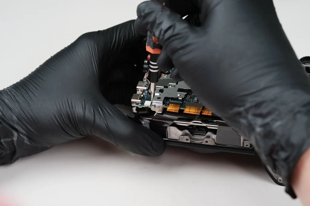
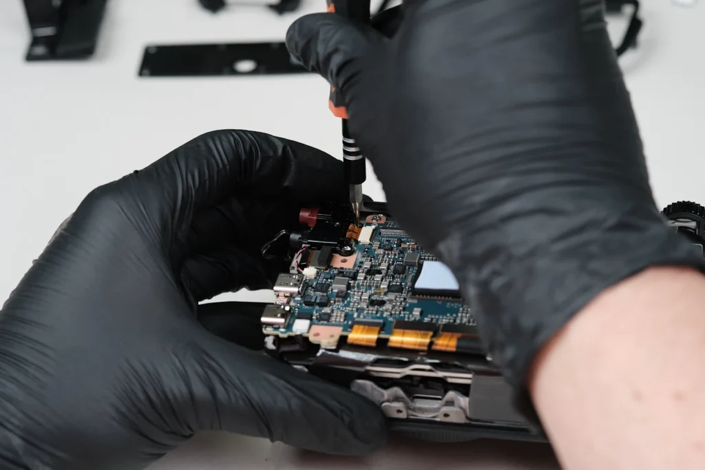
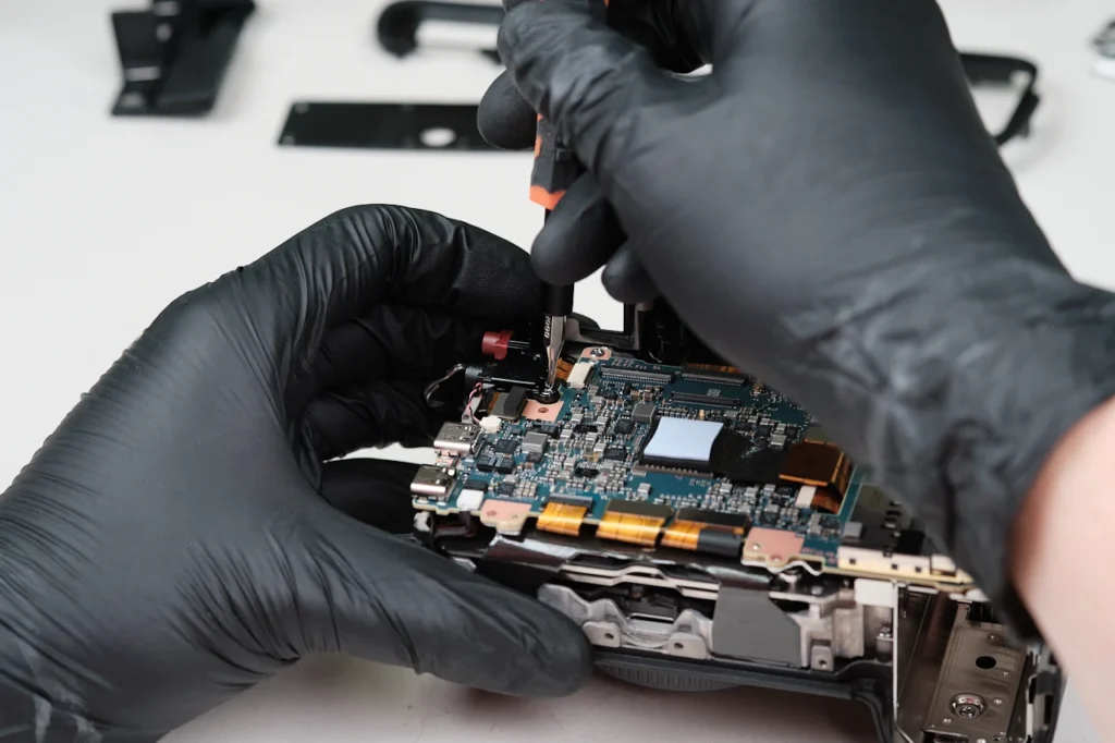
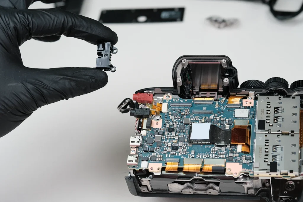
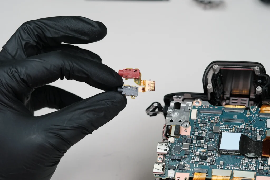
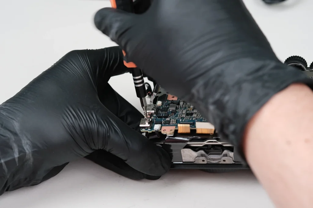
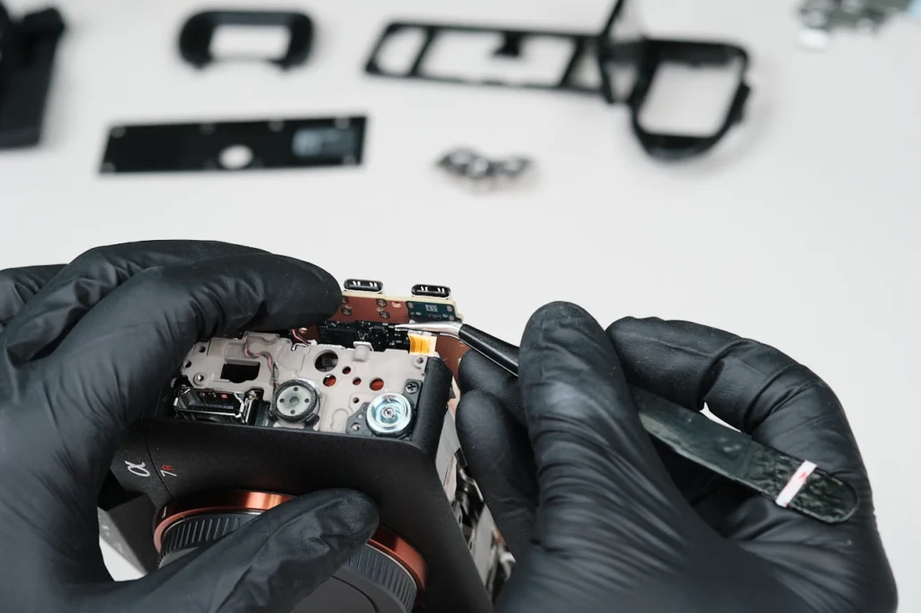
Two screws hold a cover over the audio input jacks.
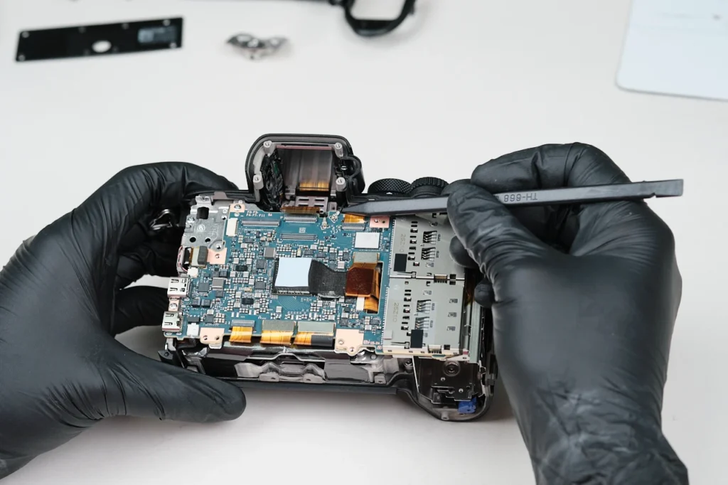
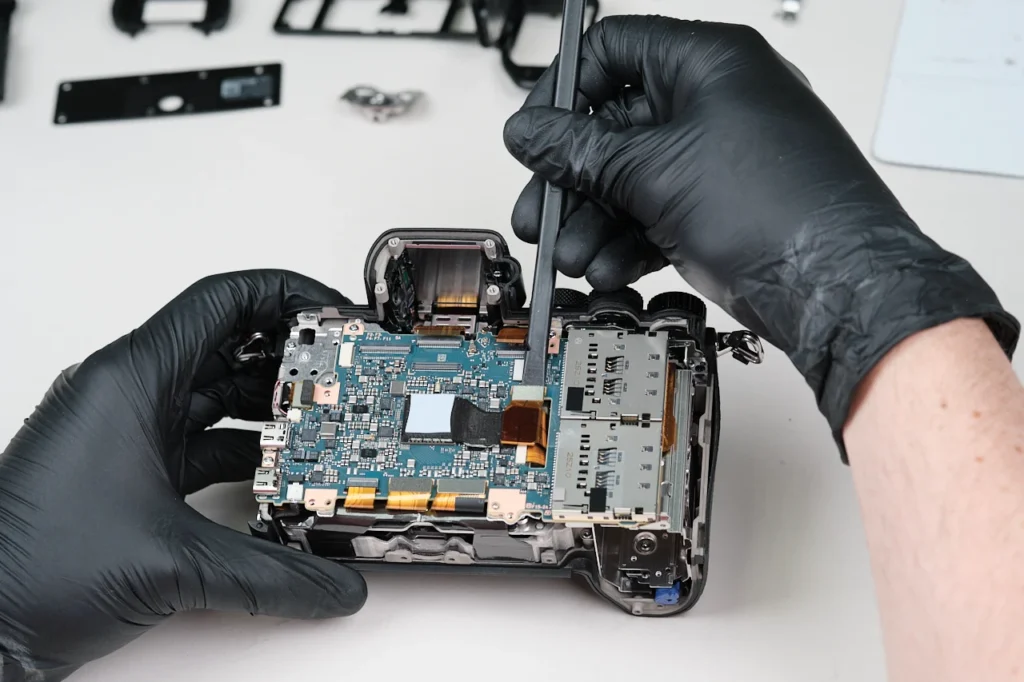
Several ribbon cables and wires are connected around the perimeter of the circuitboard.
Three wires throughout the were connected.
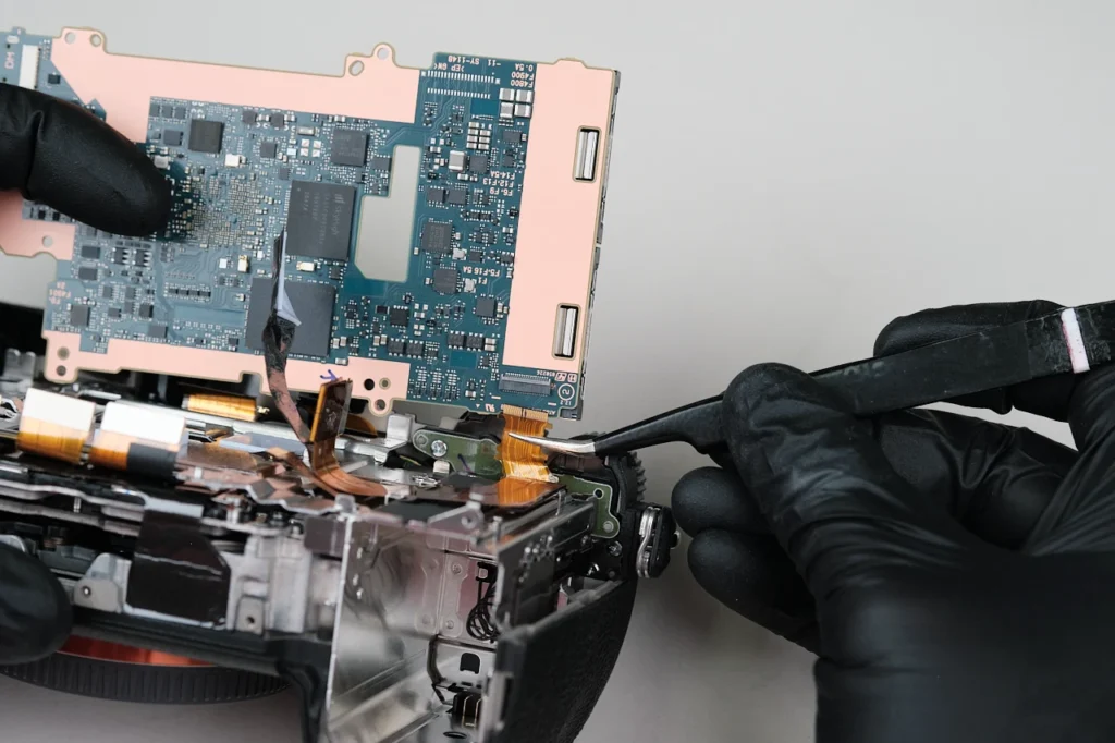
One last heat transfer tape was connected to the circuitboard. One ribbon cable was attached to the circuitboard hidden underneath this heat transfer tape.
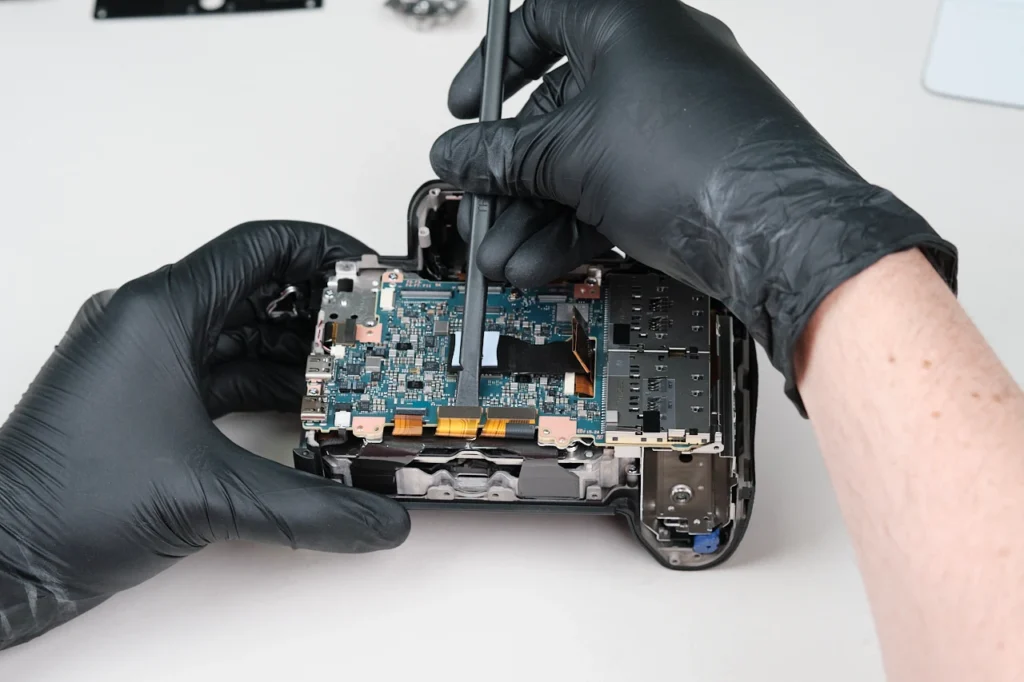
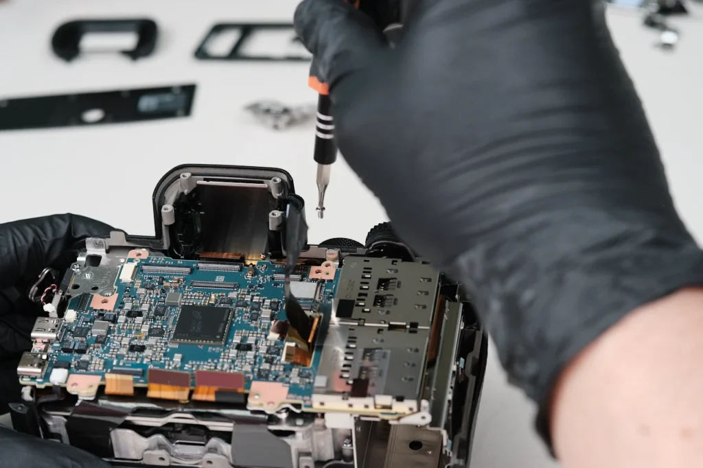
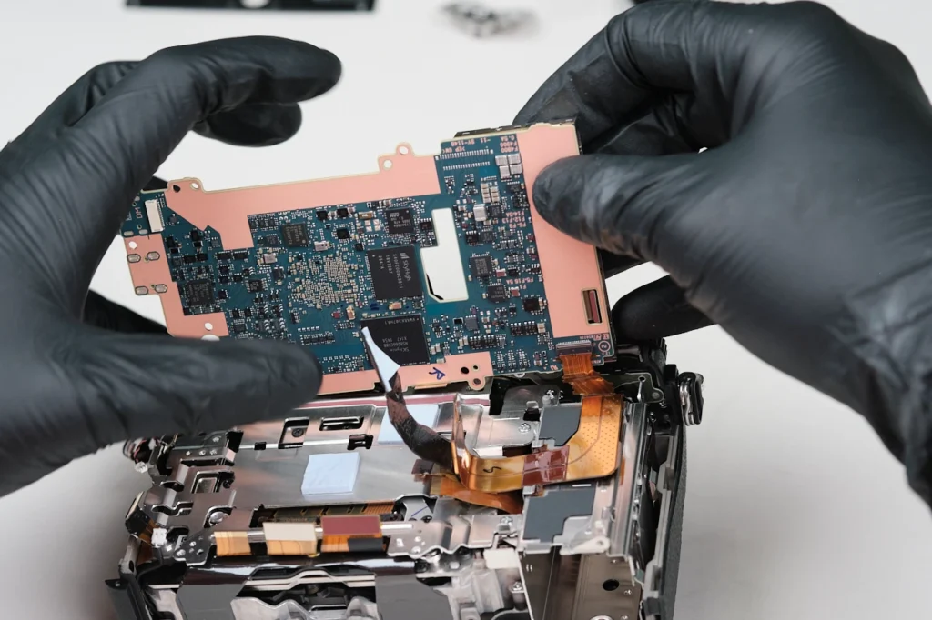
The circuitboard was held down with four screws altogether. At this point, the circuitboard was almost fully detachable from the body, as there are a few connections beneath the PCB itself as we will see in the next section.
We had to be careful in detaching the circuitboard. Two more ribbon cables were attached to the posterior of the circuitboard.
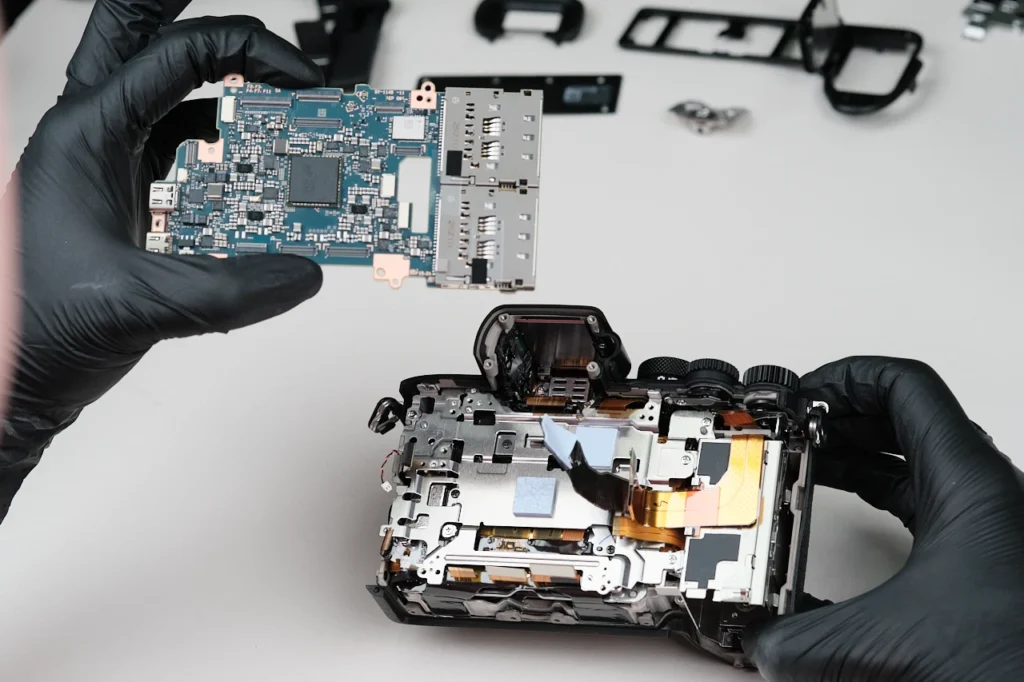
And here we have the circuitboard detached. There is just a few more things to remove as we reach the camera’s sensor.
Two screws within the EVF compartment hold down a bracket inside of it.
Five screws around the bracket of the camera were removed. These were the last parts to be removed so we could detach the top panel.
Here is the top panel removed. Altogether, it was held in place with seven screws.
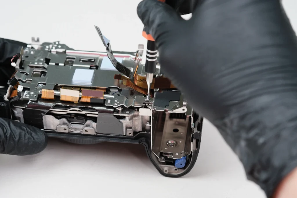
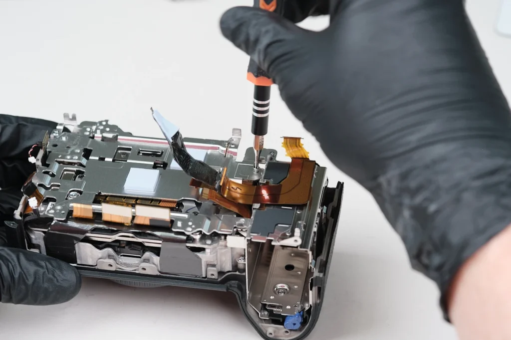
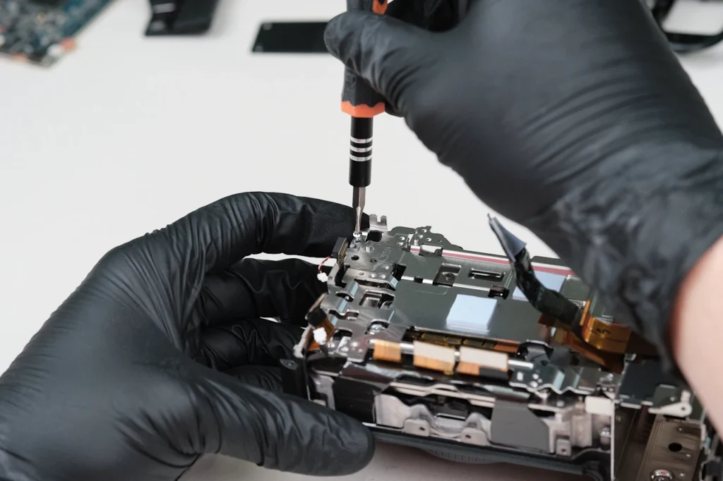
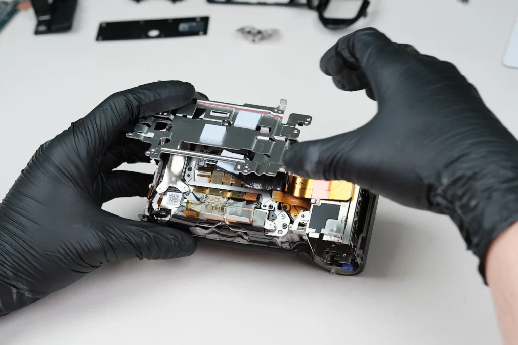
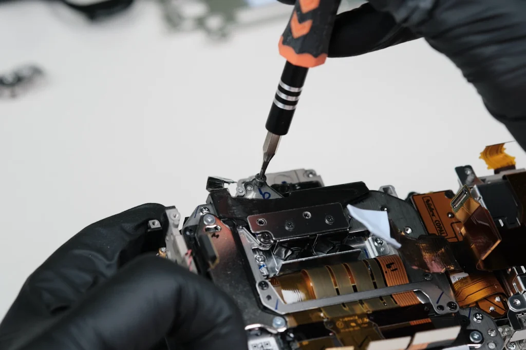
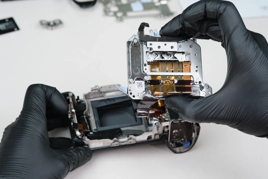
Three screws hold down the entire bracket frame.
The bracket removed from the body.
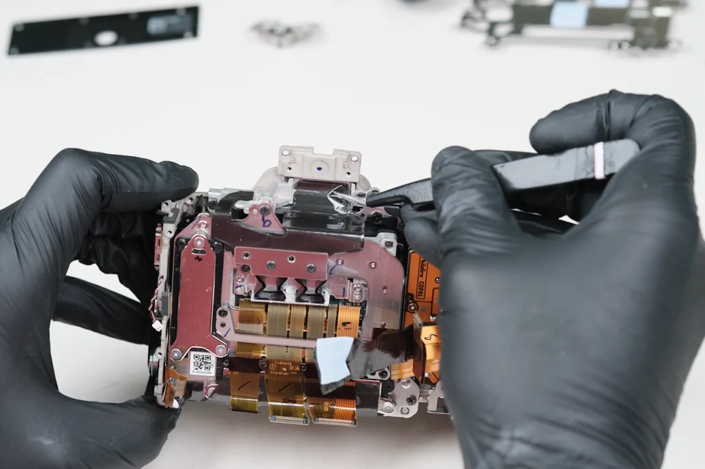
Heat transfer tape surrounds the sensor’s frame.
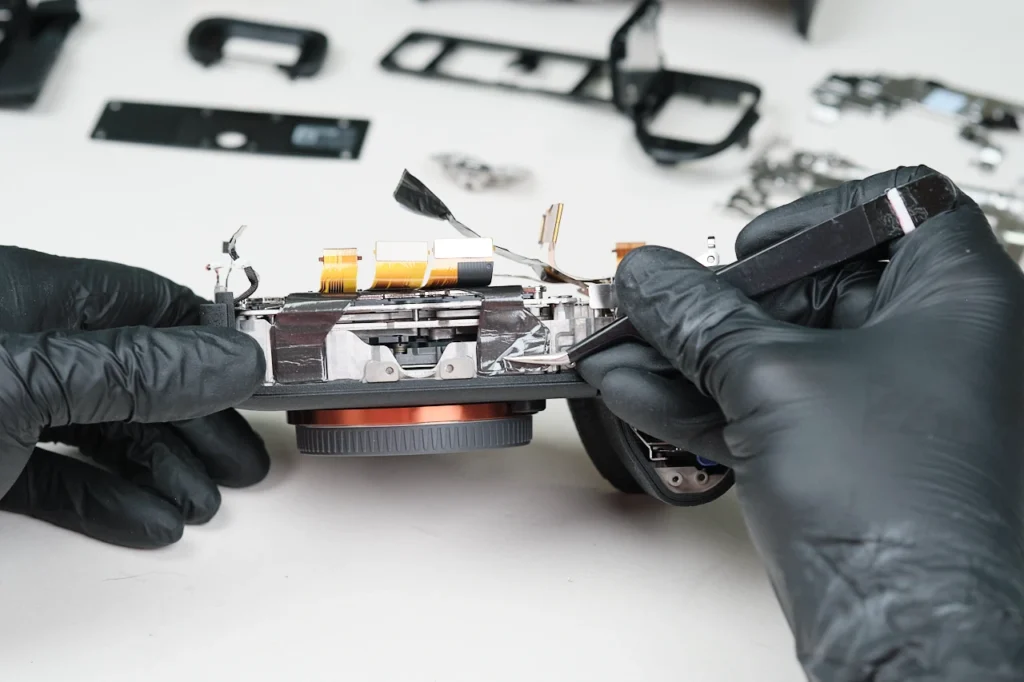
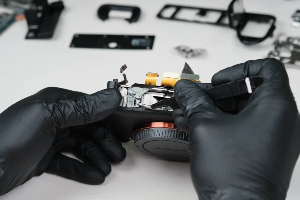
Hidden heat transfer tape on the side of the camera.
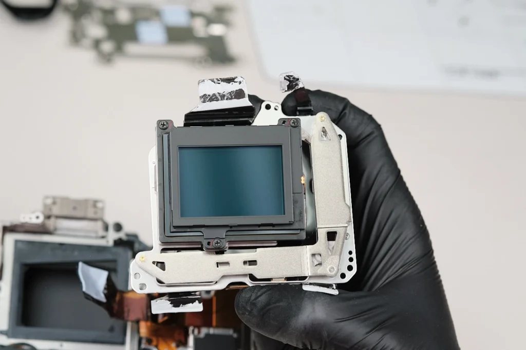
Three screws hold down the camera sensor.
Finally, here is the camera sensor removed from the body.
For a Sony mirrorless camera, the A7RVI was comparable to the difficulty it takes to teardown other Sony cameras in this lineup. It was similar to the Sony A7RIII, A7RIV, and A7RV in terms of difficulty since it contained many layers and screws within the camera’s build.
Thanks for reading. We feature a new camera teardown every month. Be sure to sign up for our newsletter so you don’t miss them!