FREE SHIPPING FOR ALL DOMESTIC ORDERS OVER $100 - NO SALES TAX OUTSIDE OF NJ!
0

Fujifilm GFX100 Teardown

Table of content

Fujifilm GFX100 Camera Overview

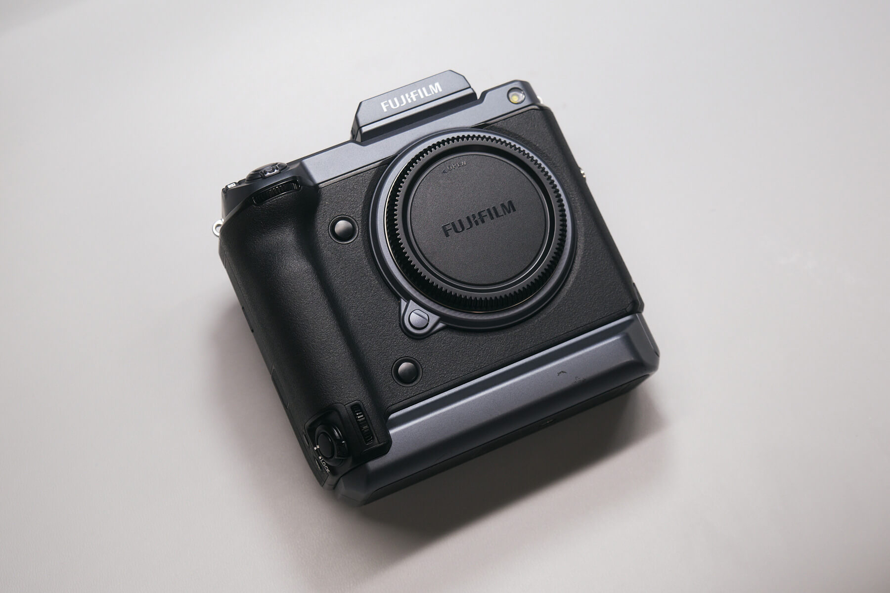
At Kolari, we managed to get our hands on the highly-acclaimed beast of a camera Fujifilm GFX100. This is just one of Fujifilm’s medium format cameras, accompanied by the GFX100S, GFX50S, GFX50S II, and GFX50R. Aside from medium format, Fujifilm has a plethora of APS-C cameras that are compatible with our Fujifilm magnetic clip-in filters.

Fujifilm GFX100 Specs and Medium Format Design

Consumers highly anticipated the Fujifilm GFX100 before its official release in 2019. It boasts an incredible 102MP medium format sensor, 5-axis in-body image stabilization (IBIS), a hybrid autofocus system, and both DCI and UHD 4K video with 10-bit 4:2:2 output. Its other features include weather sealing, removable EVF, dual-battery setup, two SD card slots, and ports for a remote control, microphone, and headphones.

With that out of the way, let’s get into this camera teardown!

Preparing the Fujifilm GFX100 for Disassembly

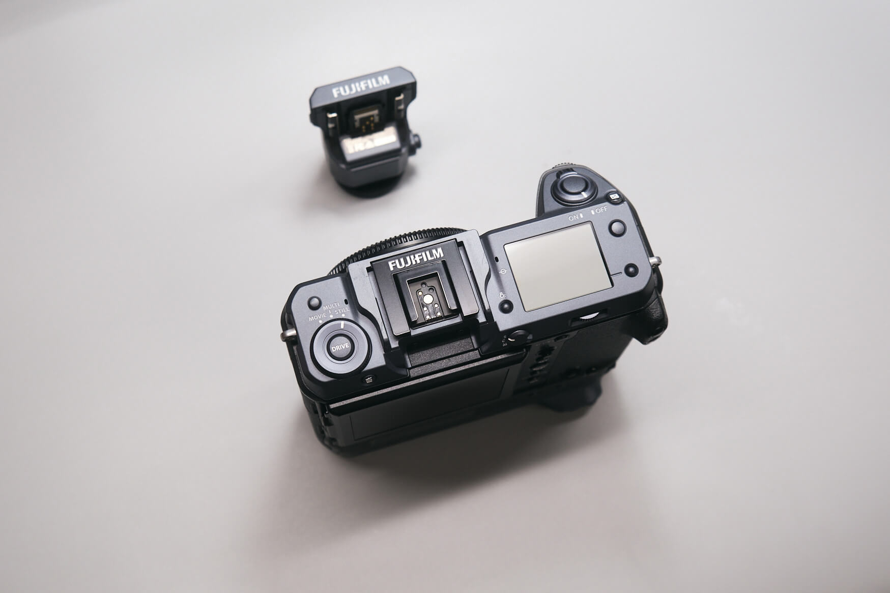
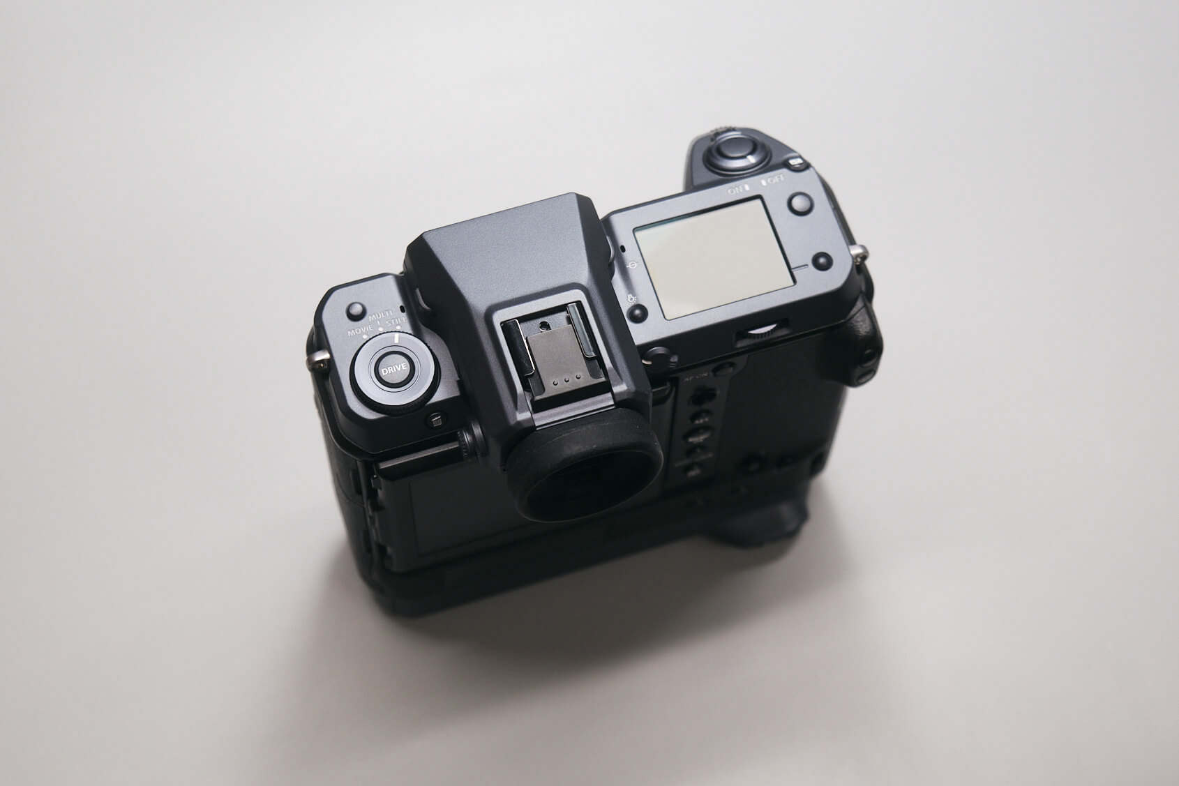
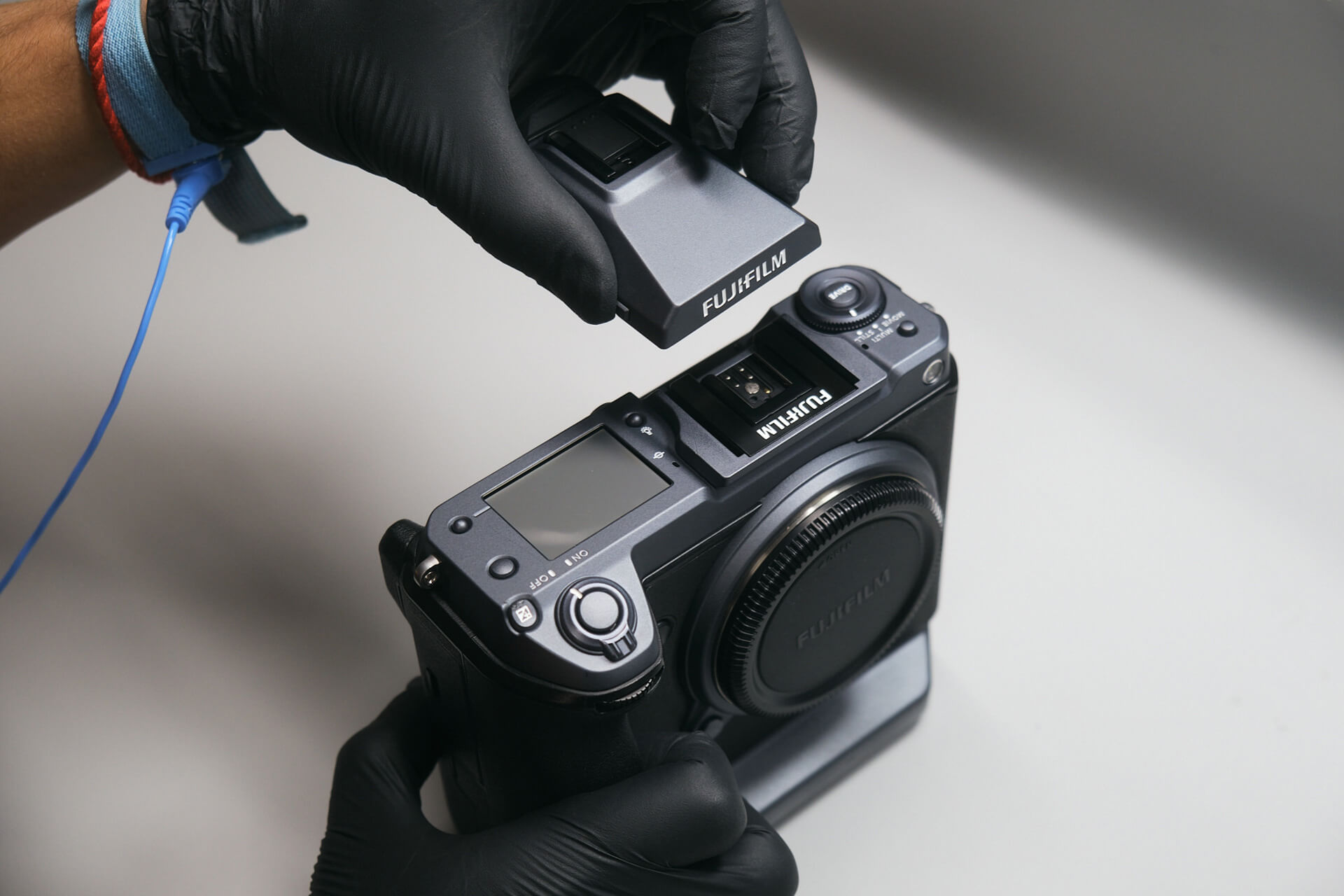
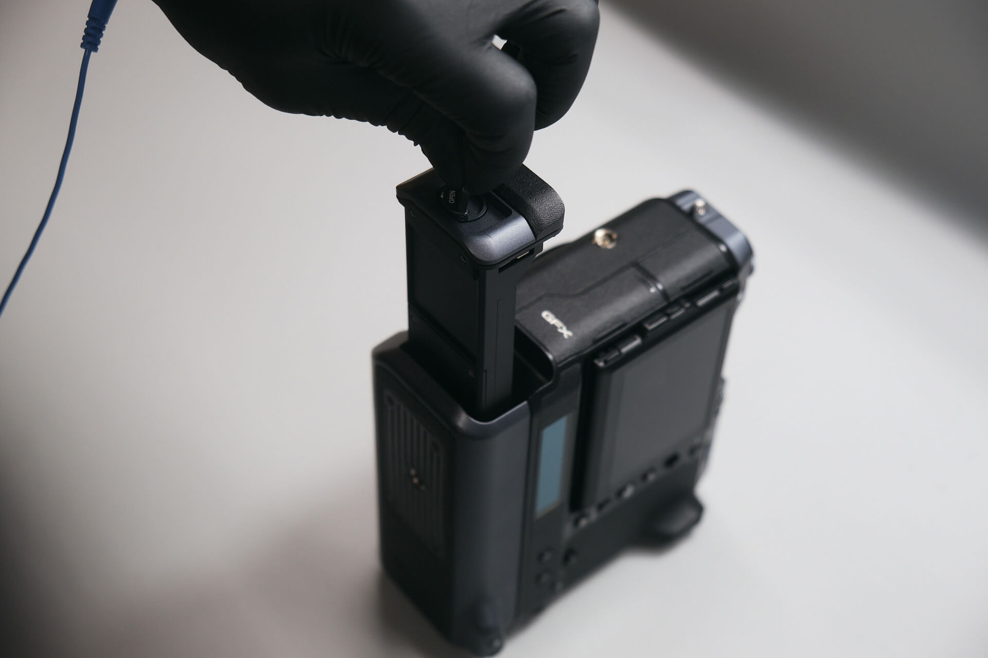
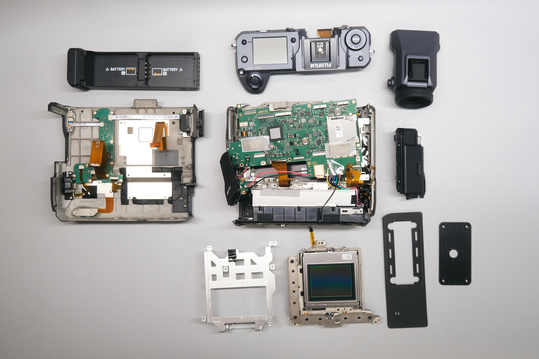
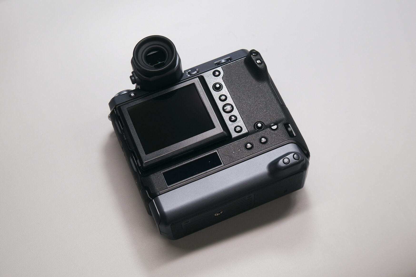
Before the main disassembly, we detached the peripherals from the camera body, namely the OLED viewfinder and the battery tray. The GFX100 features a detachable viewfinder for other attachments.

Removing Exterior Screws and Hidden Grip Screws

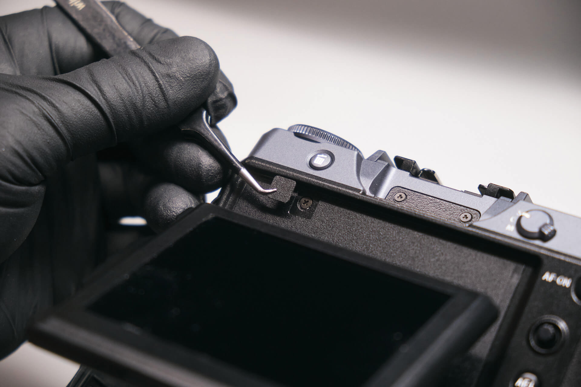
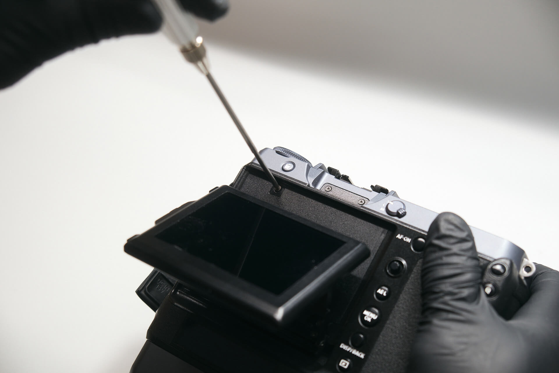
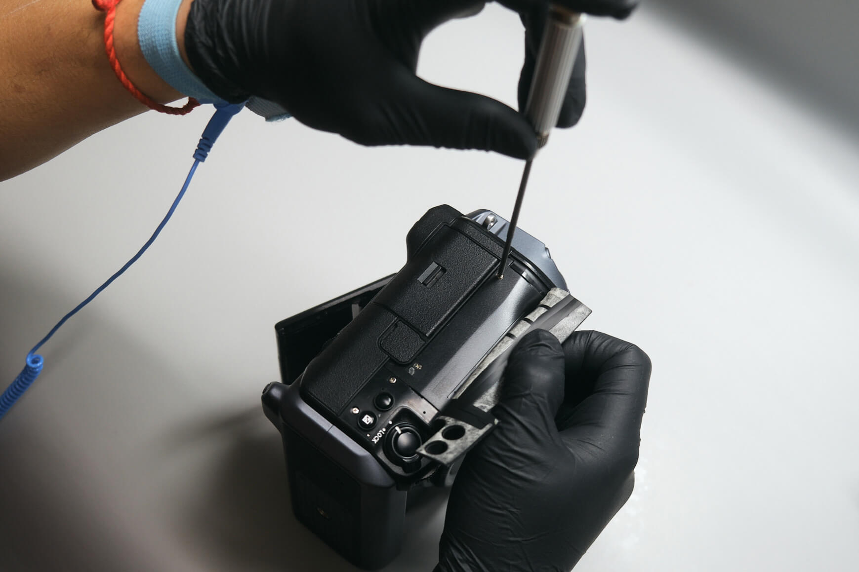
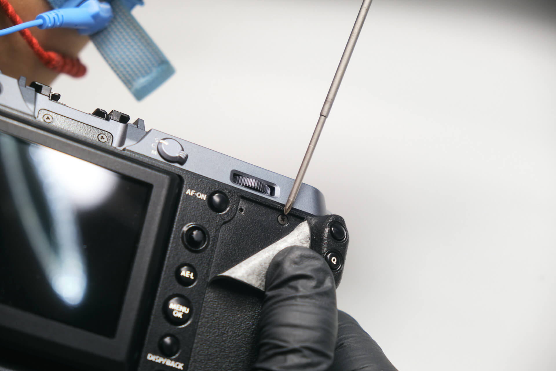
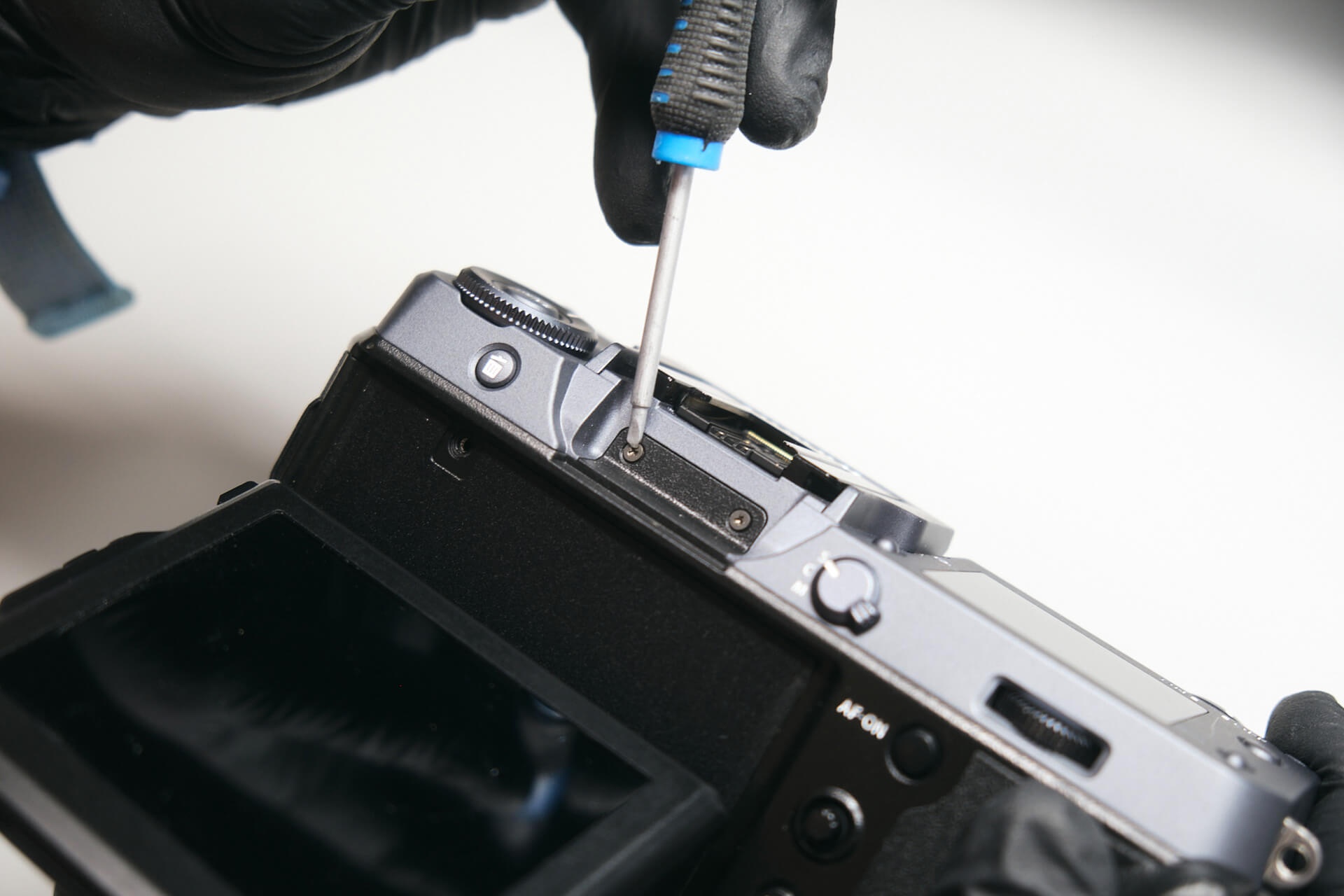
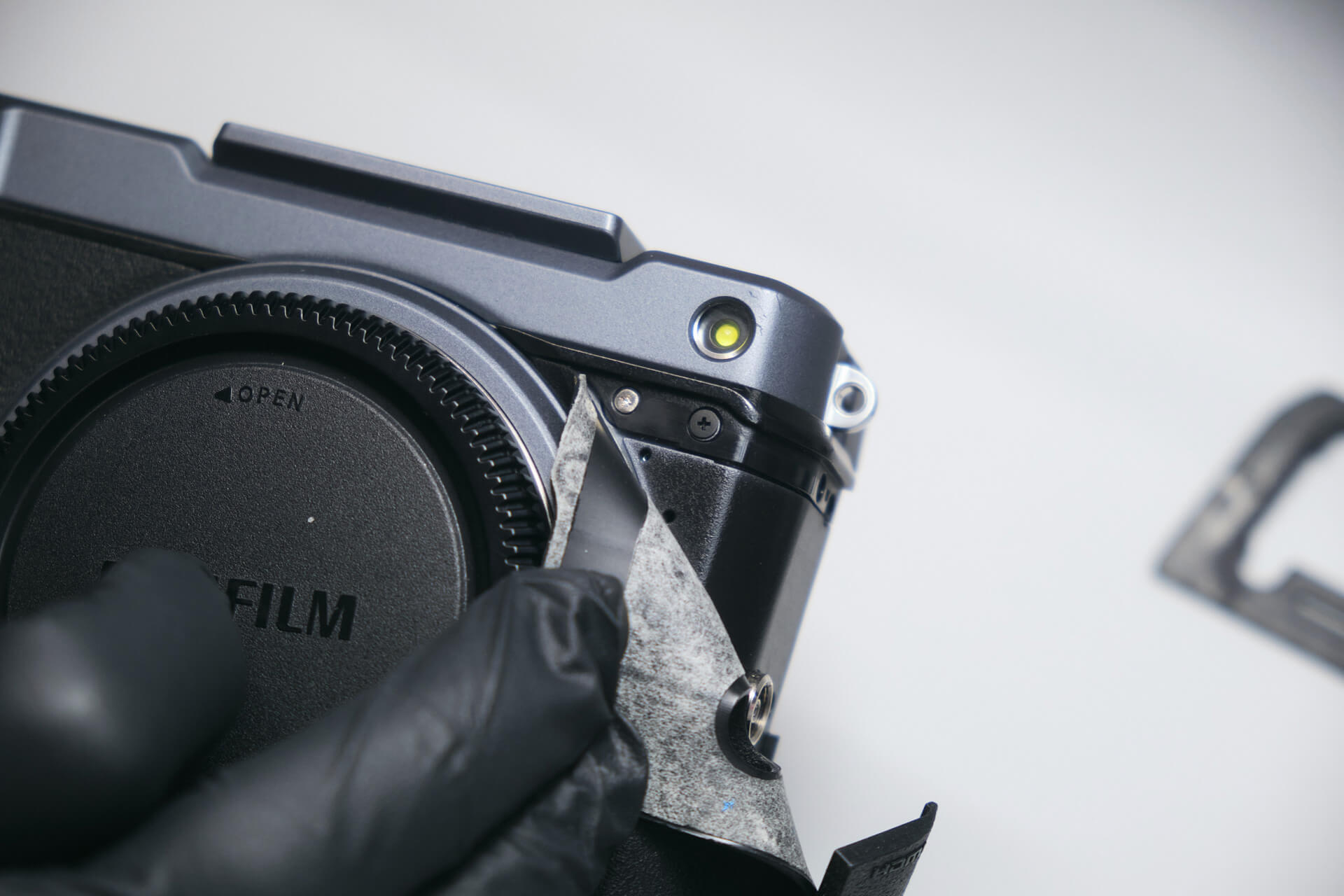
Typically when disassembling cameras, many hidden screws keep the camera together. One of the first ones we spotted was under the LCD monitor, which required us to gently peel off the adhesive cap and remove the screw.

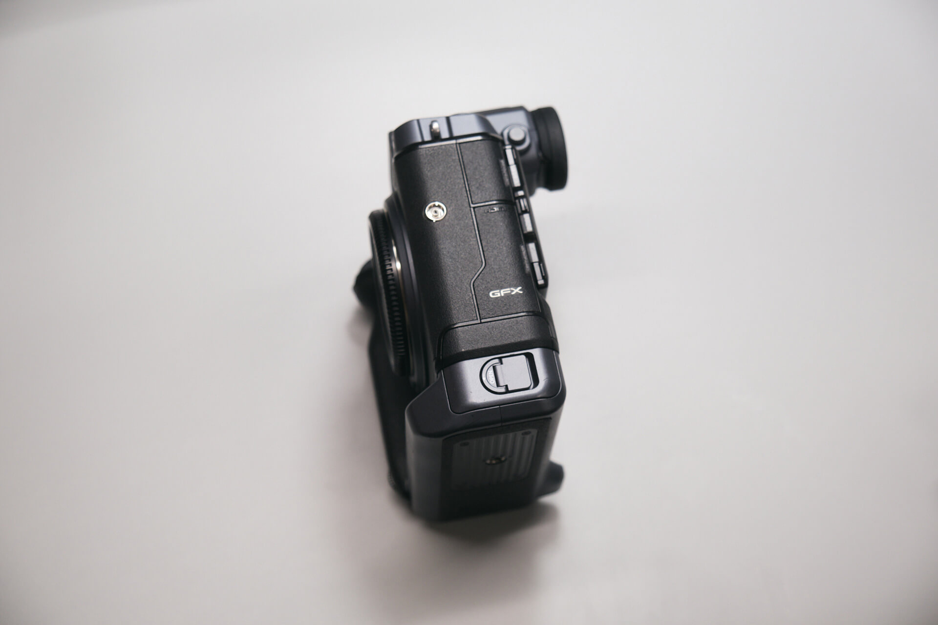
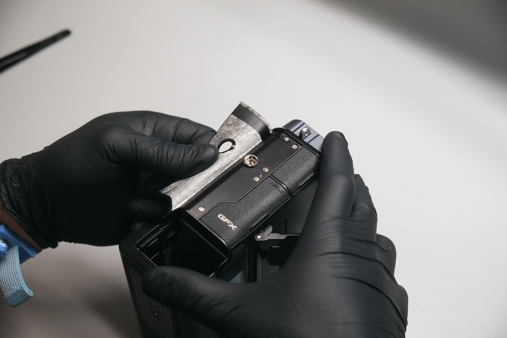
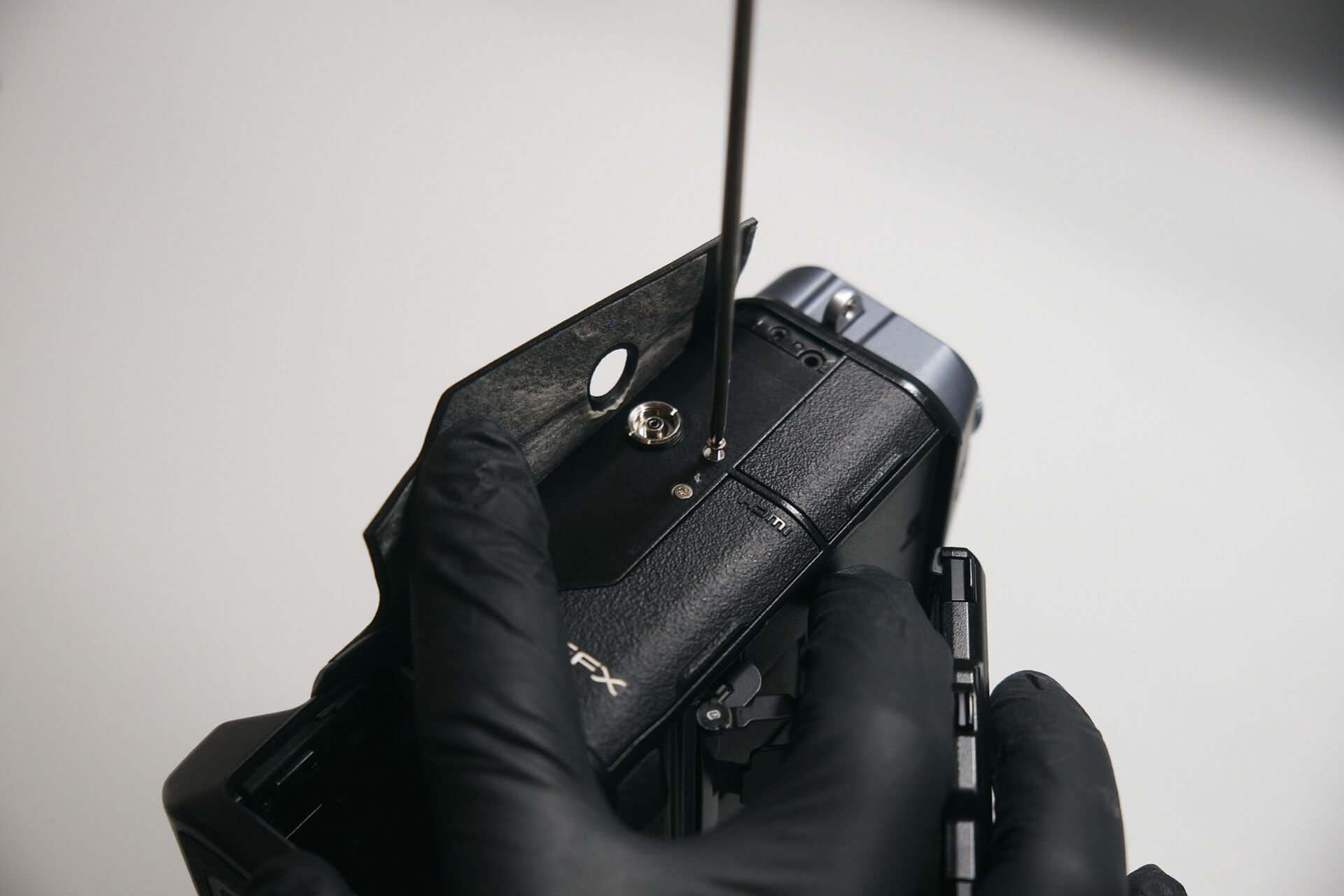
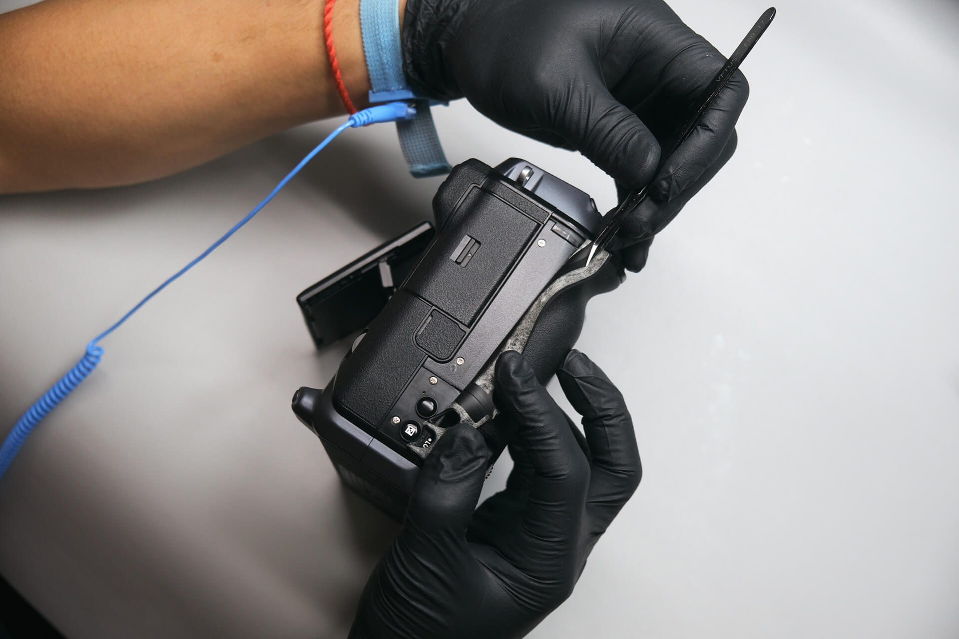
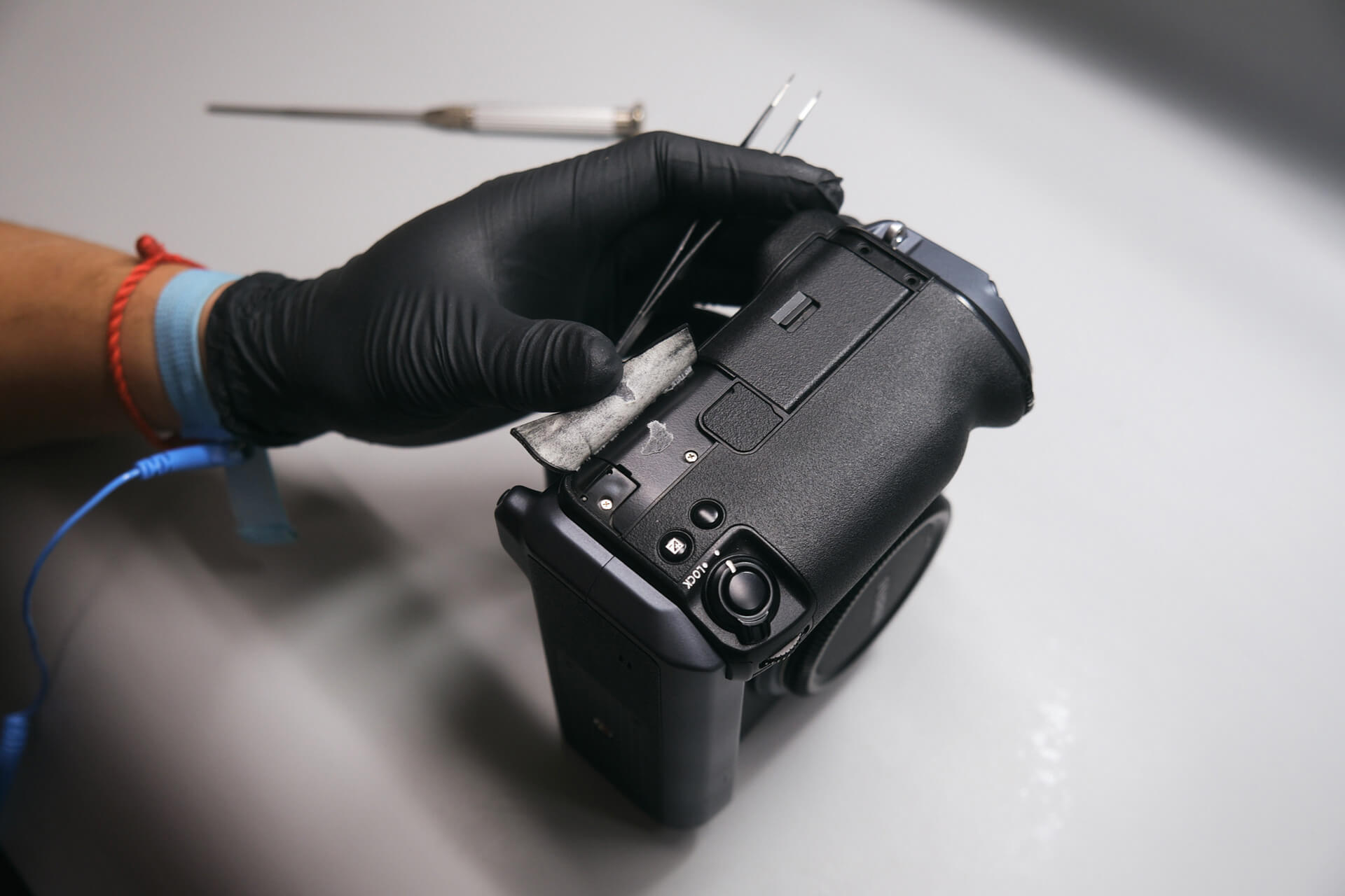
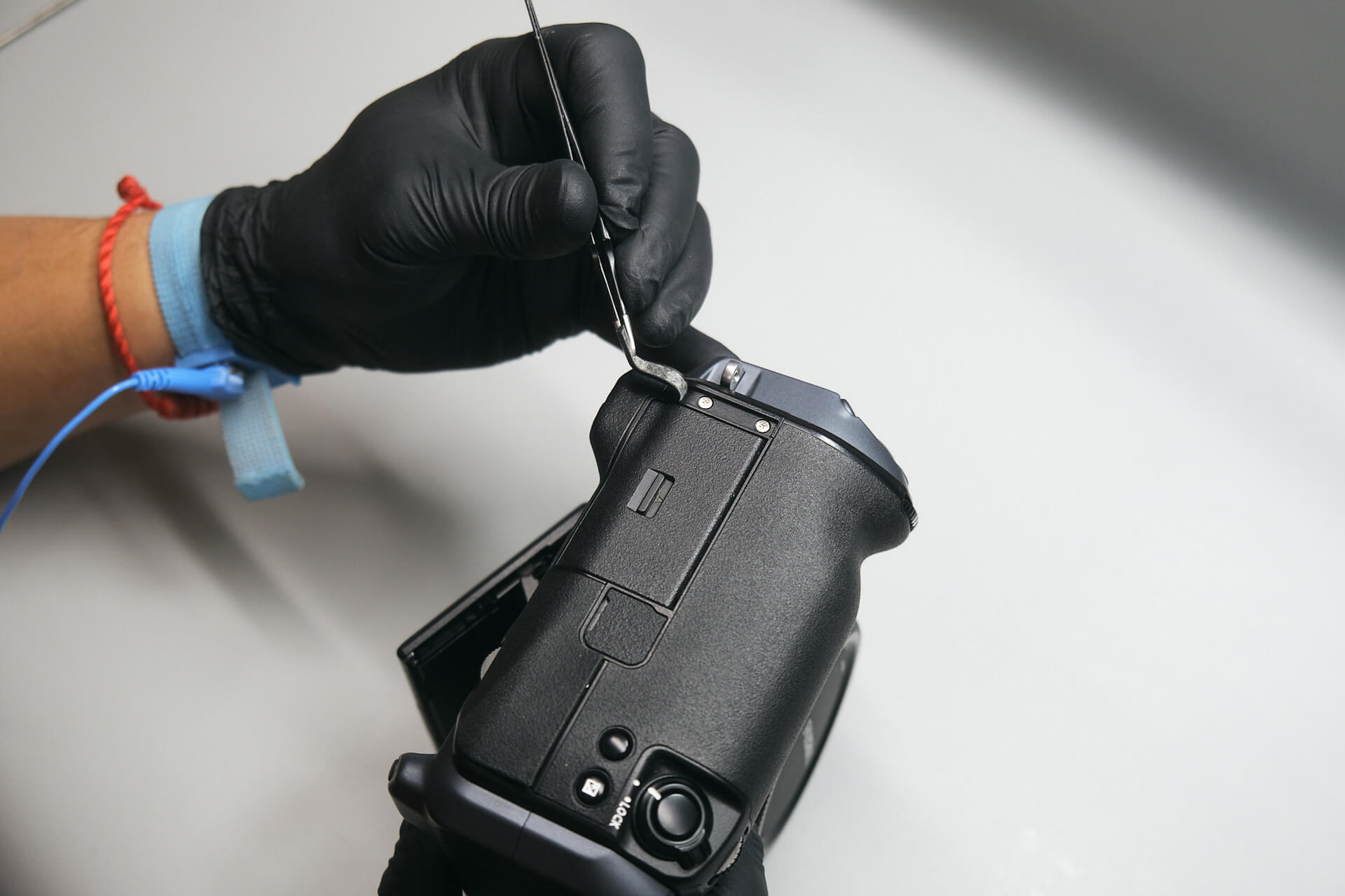
The main screws holding the camera body from the outside are usually underneath the rubber grips. We popped off the dust cap on the port side and removed a screw between the HDMI and 15V DC jack. Peeling back the rubber grip revealed five silver screws.

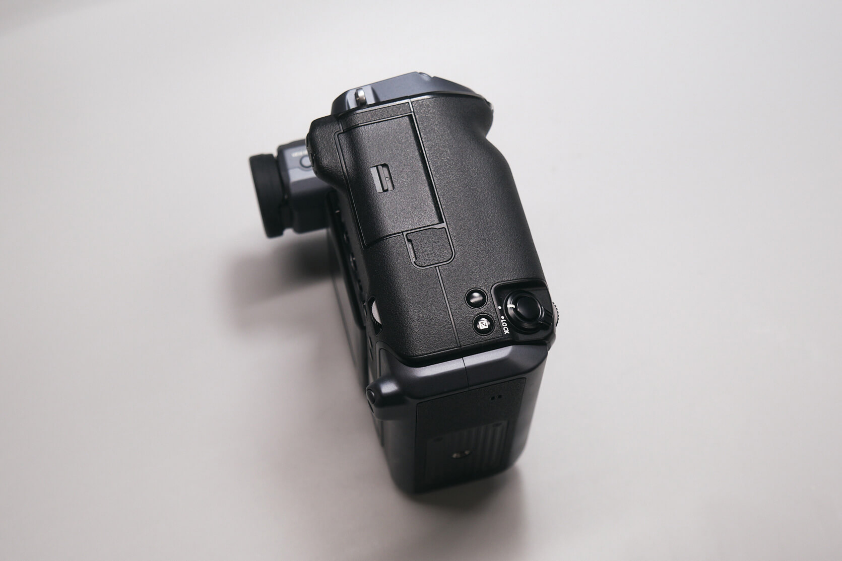
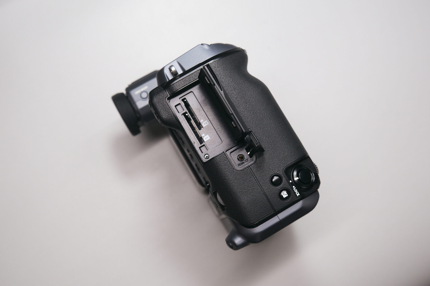
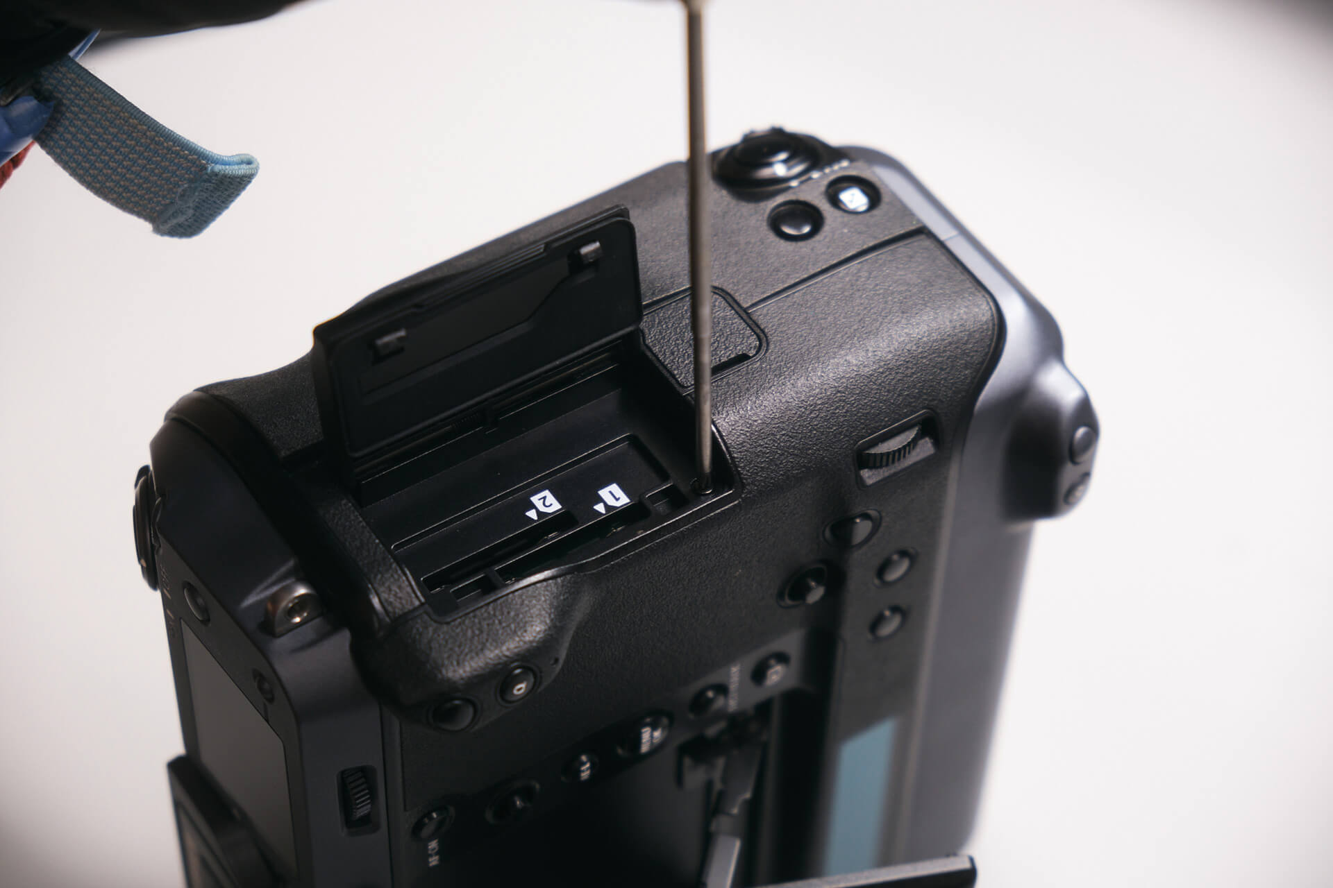
We peeled back the rubber grip on the camera’s right side to remove four silver screws. We found another hidden below SD card slot #1 when we opened the card door. Below and above the card door, we removed four more screws.

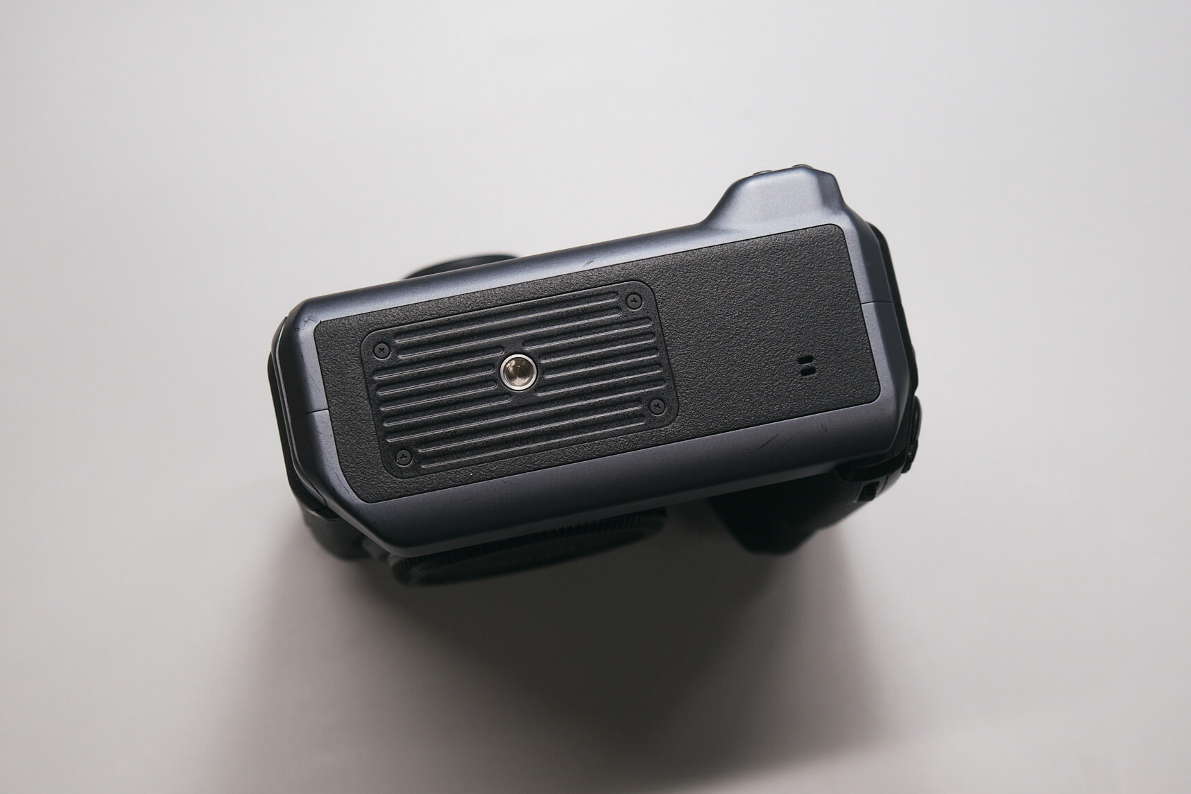
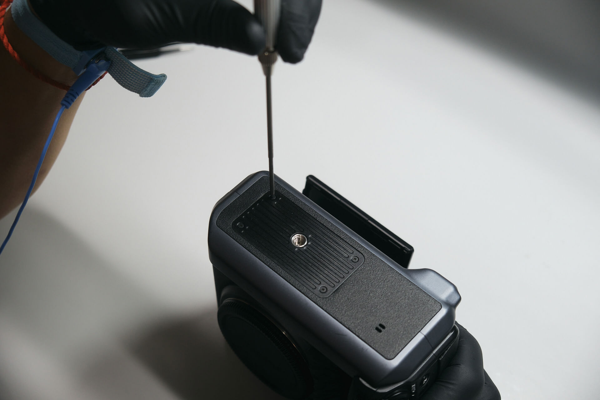
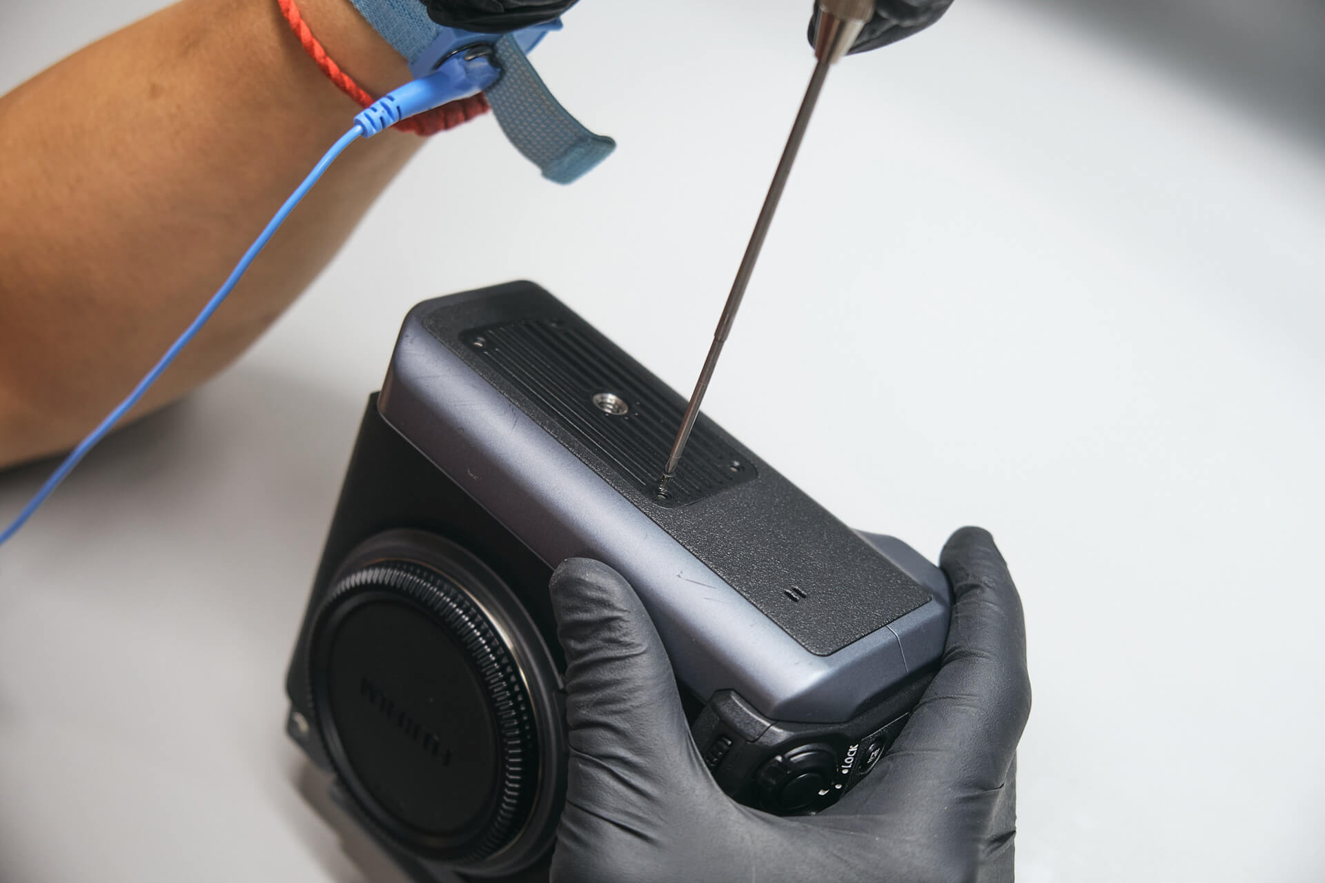
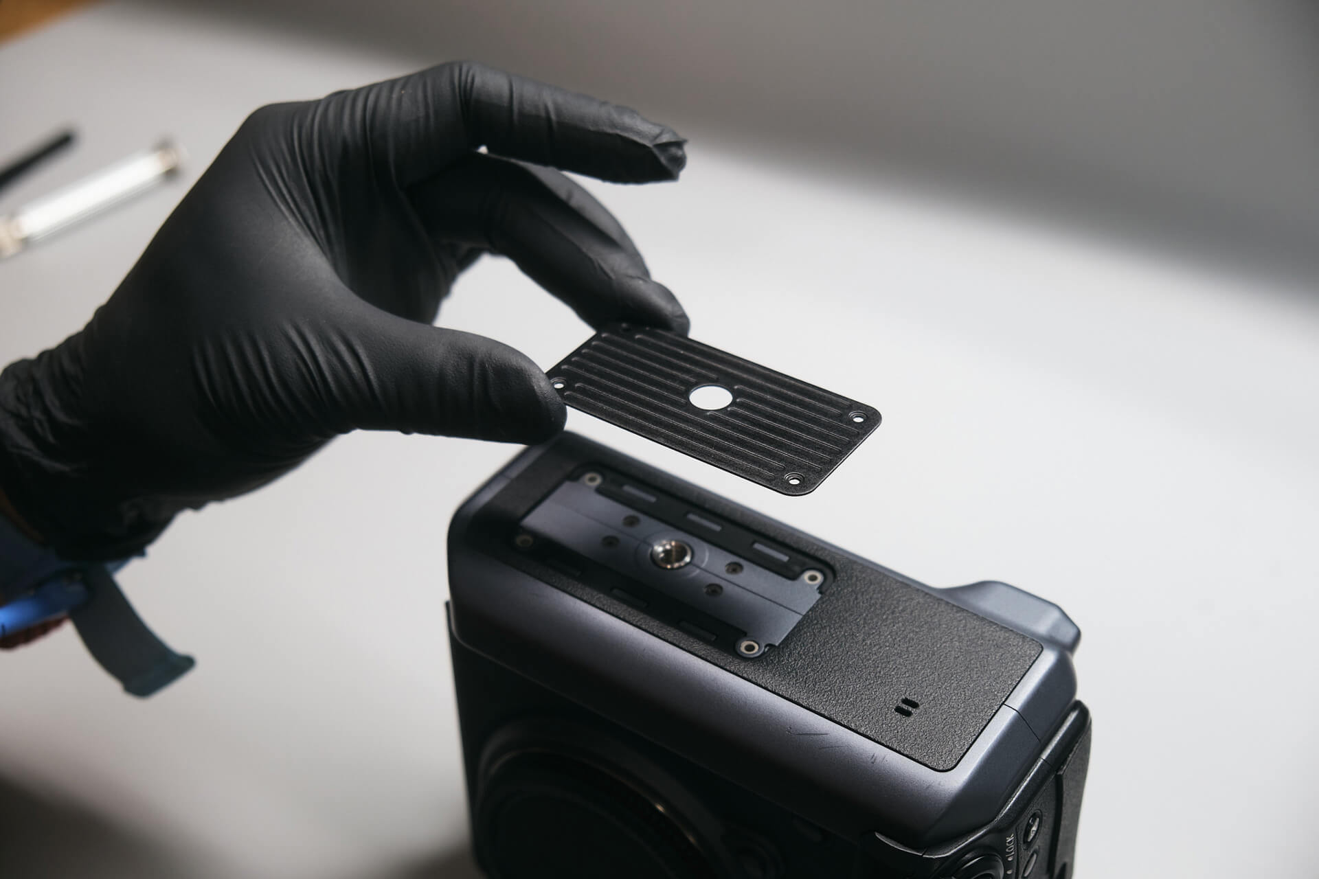
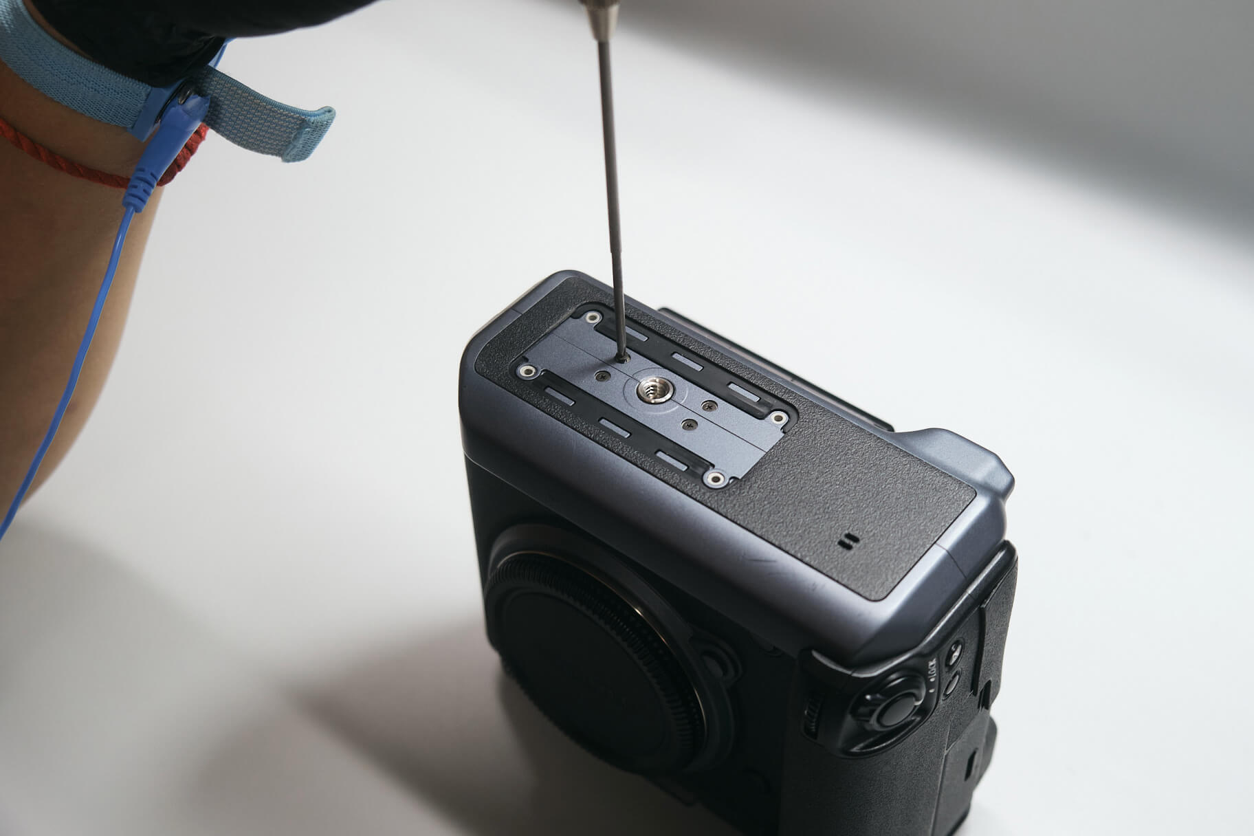
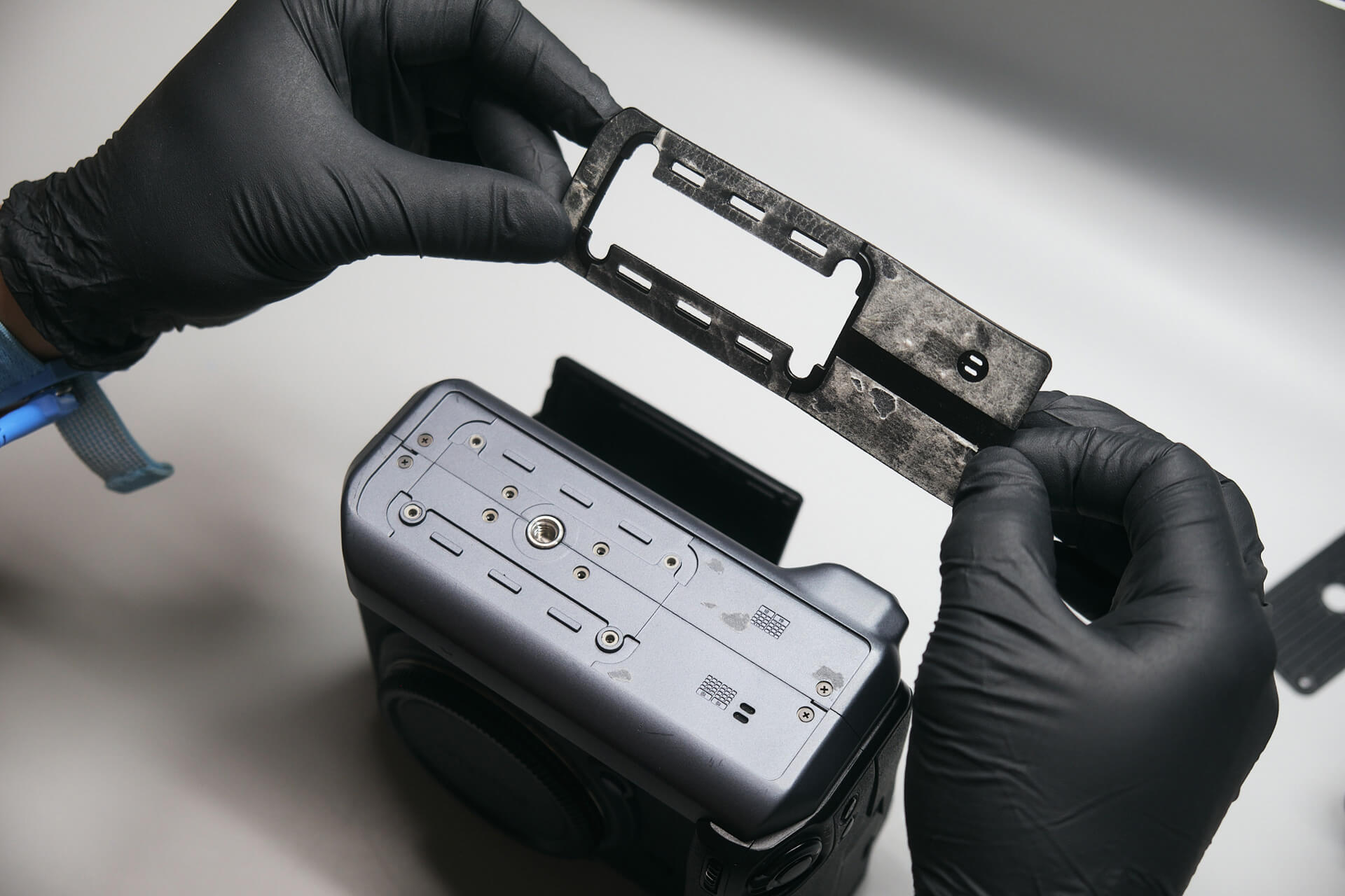
The baseplate was only held down with four screws, which made for easy removal. There were another four screws below the baseplate.

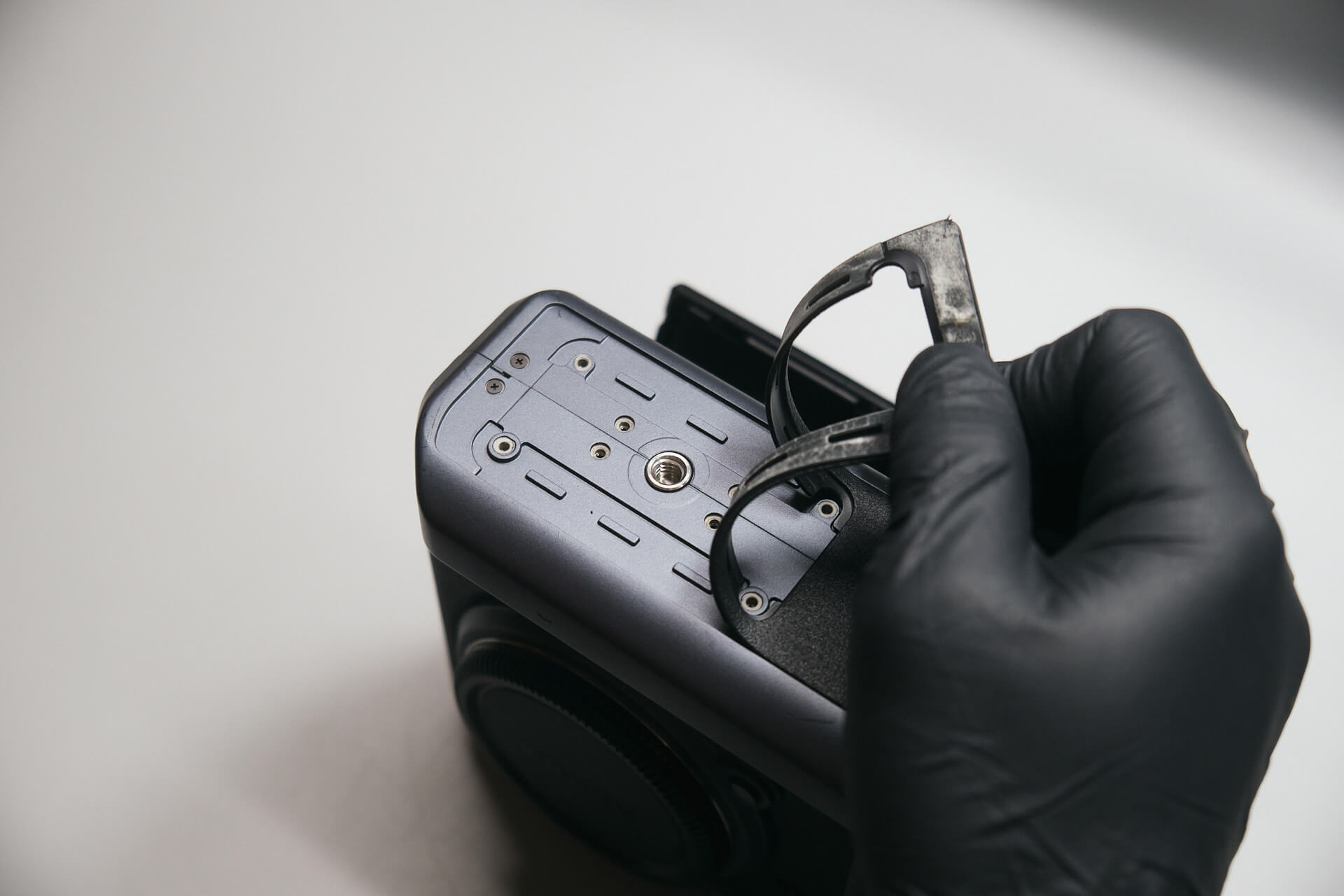
Of course, we had to peel off more of the rubber grip to find more screws. In this case, removing it revealed four more screws. Overall, there were a total of twelve screws on the bottom of the camera.

We peeled back the rubber grip on the back panel and removed a screw under the rear command dial. Two spline screws were removed as well.

Removing the Rear Panel and Ribbon Cables

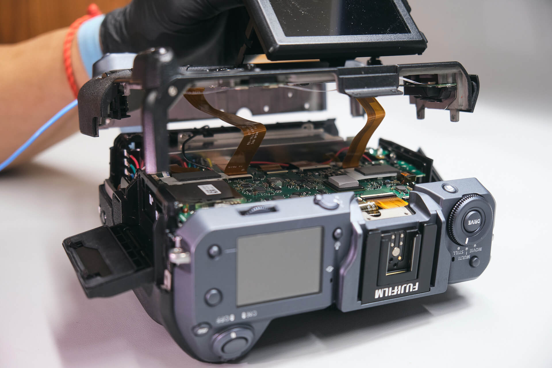
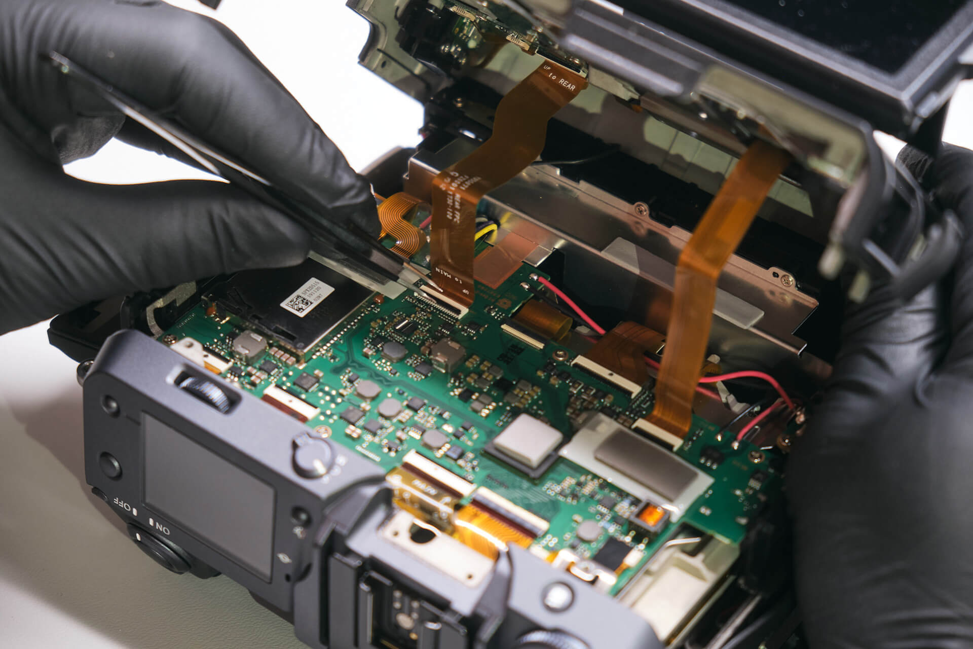
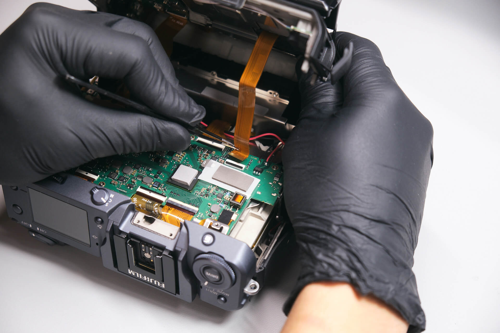
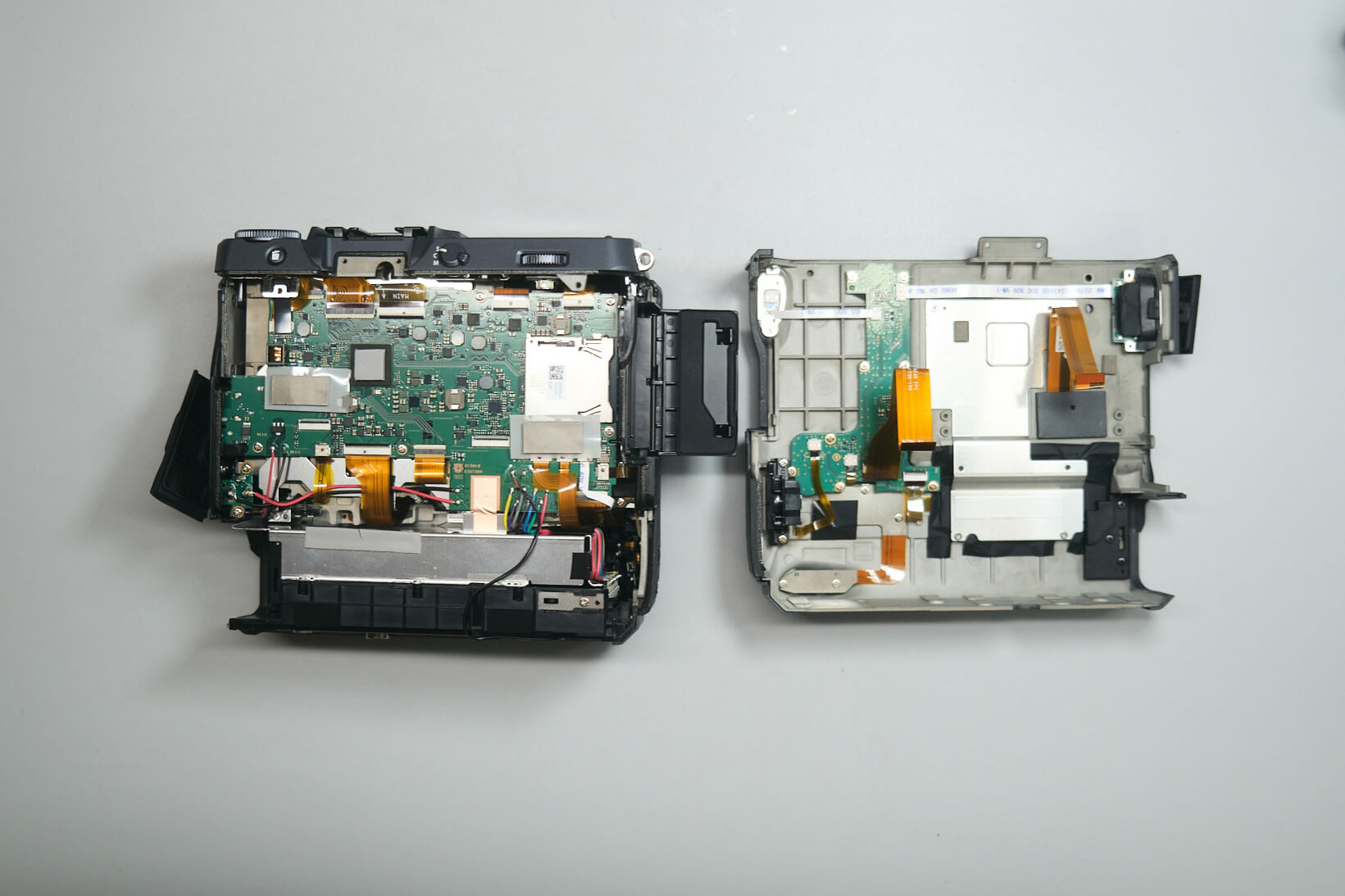
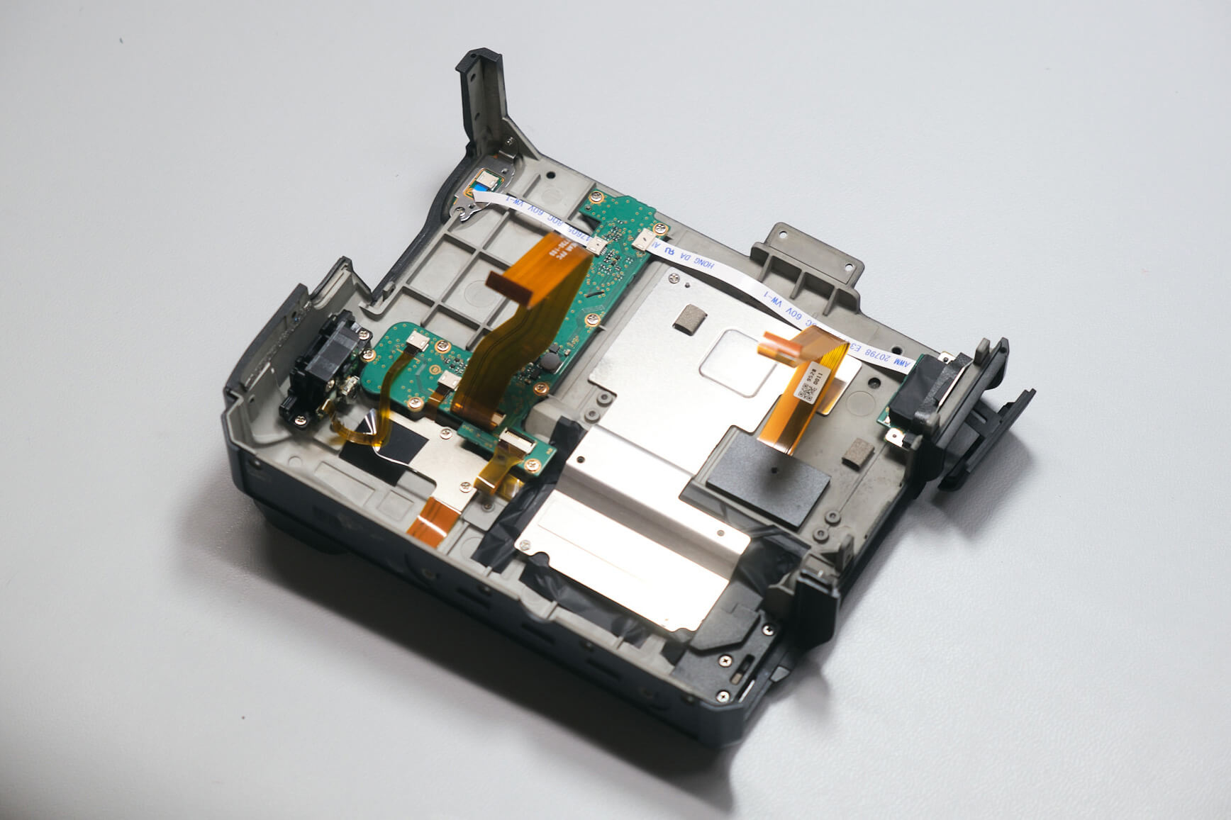
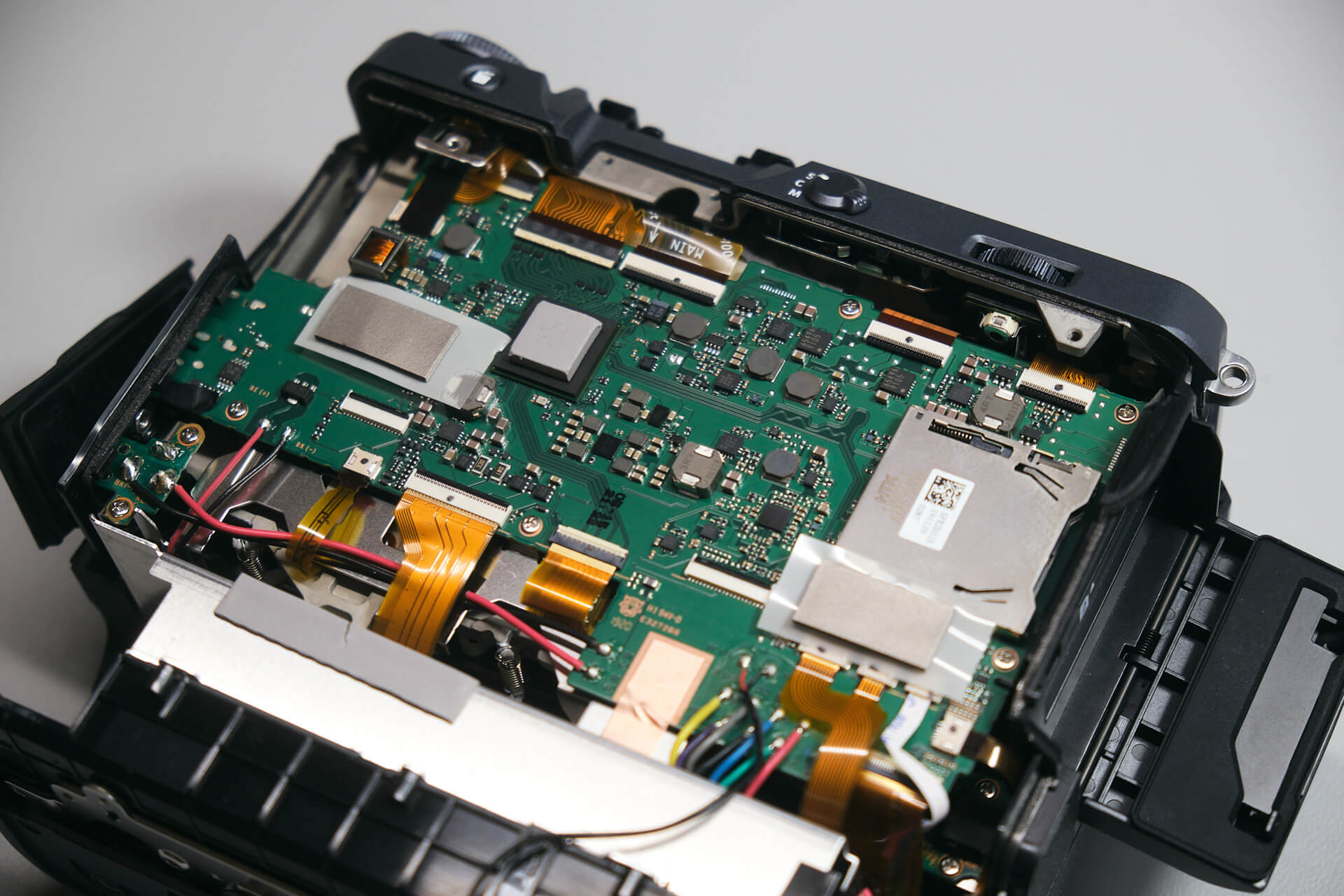
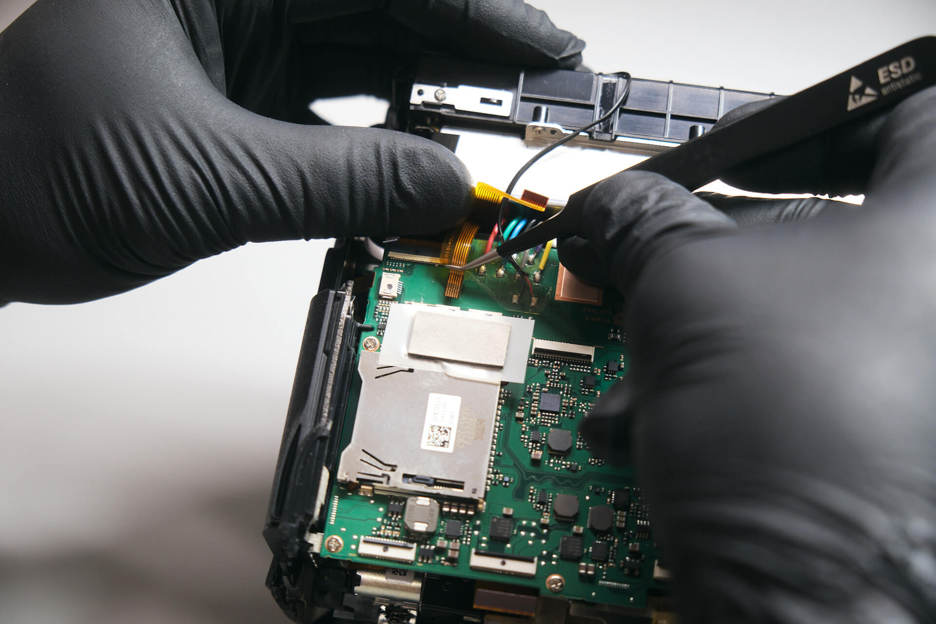
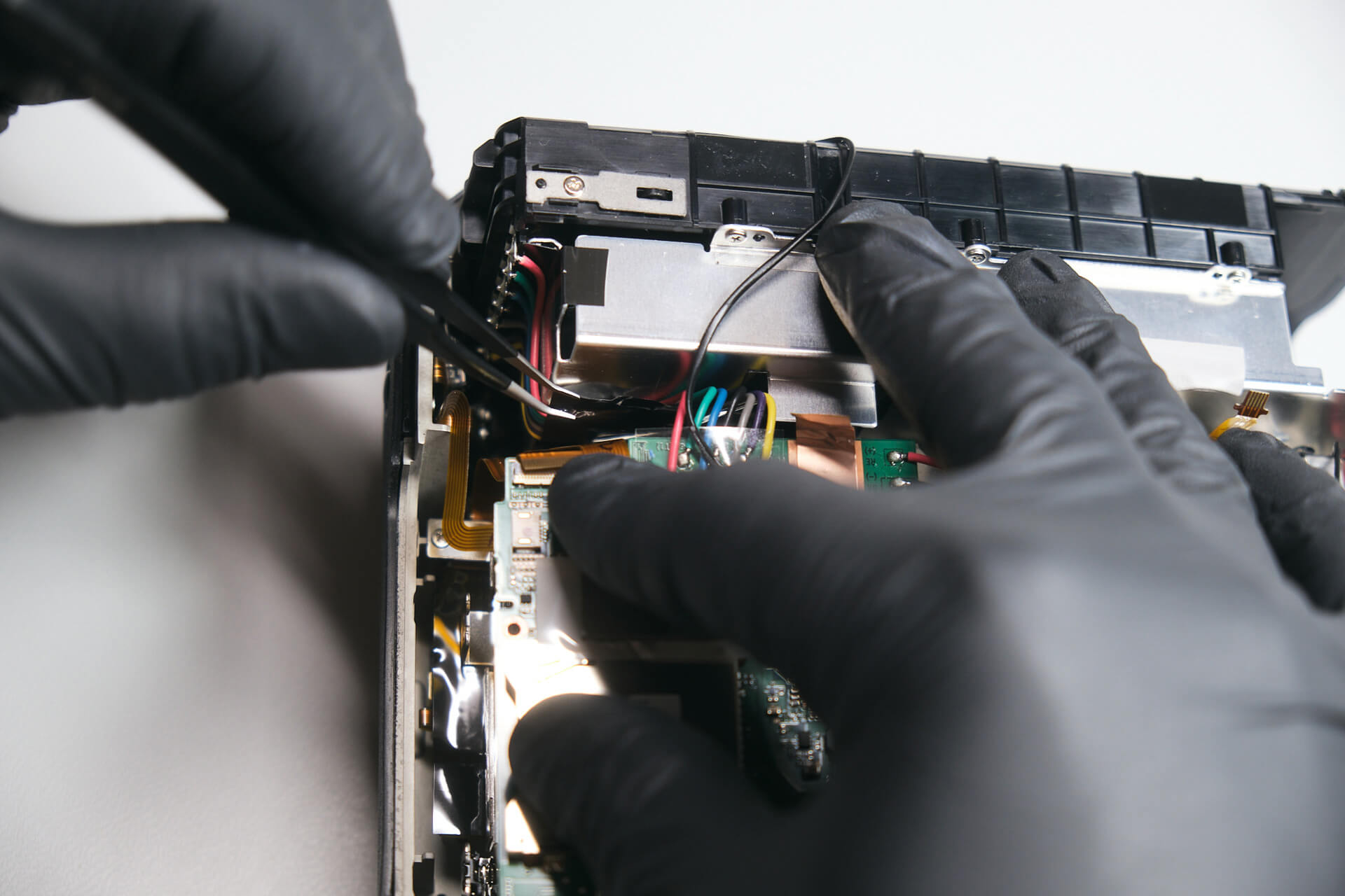
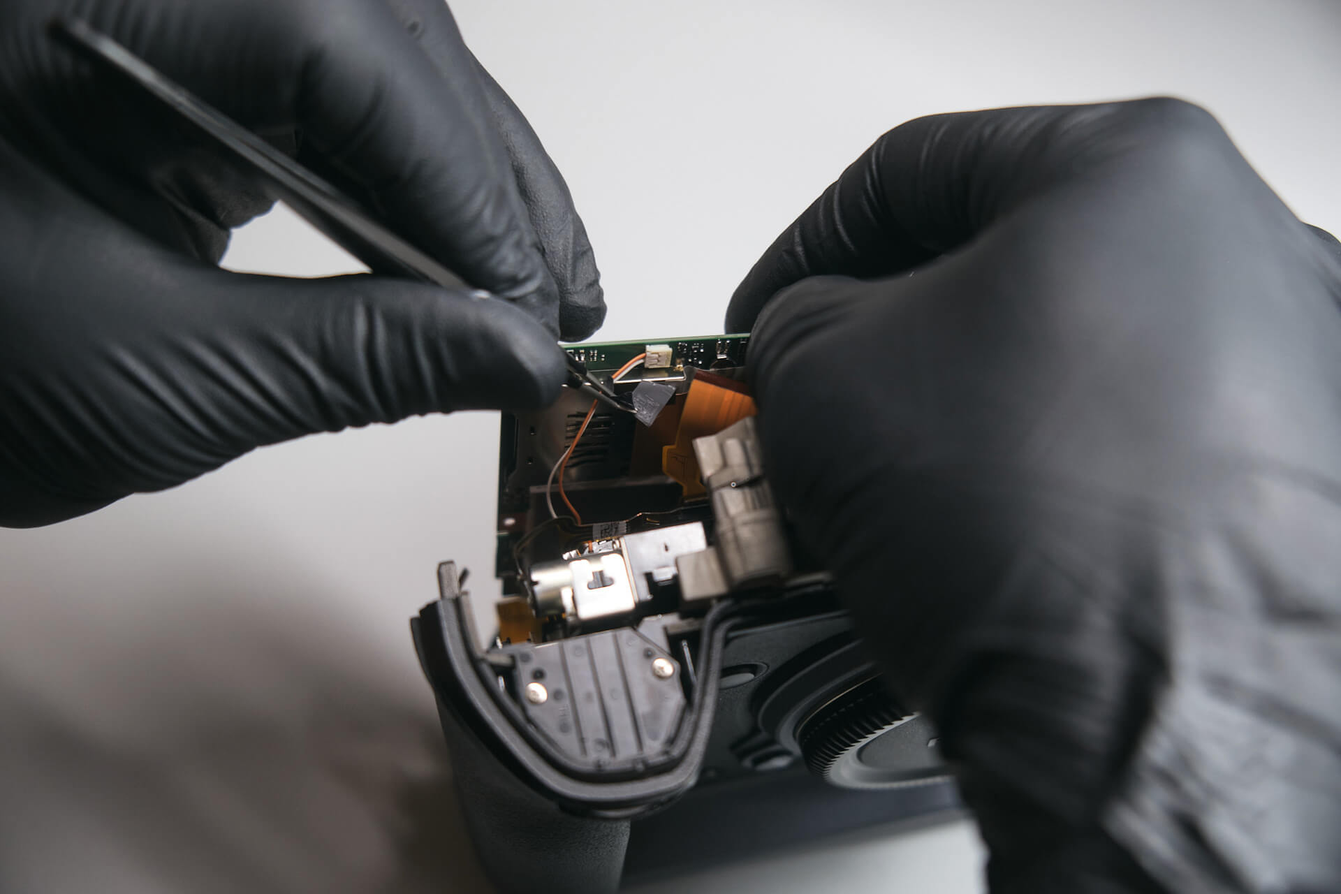
With all screws removed, we were able to lift the back panel. Before disconnecting, however, we needed to disconnect the LCD and rear button ribbon cables from the circuit board.

Removing the Top Panel and Accessing Internal Connections

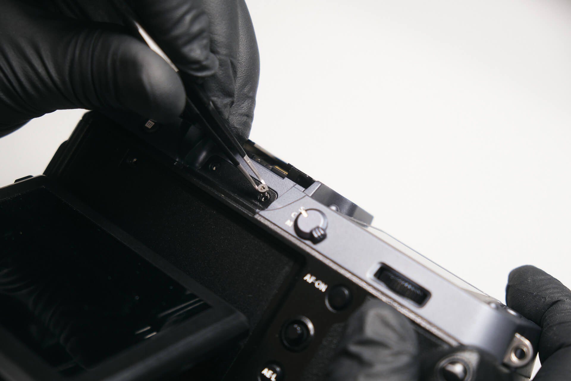
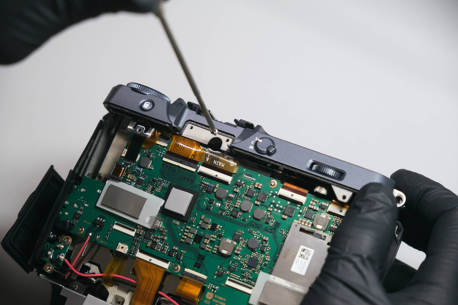
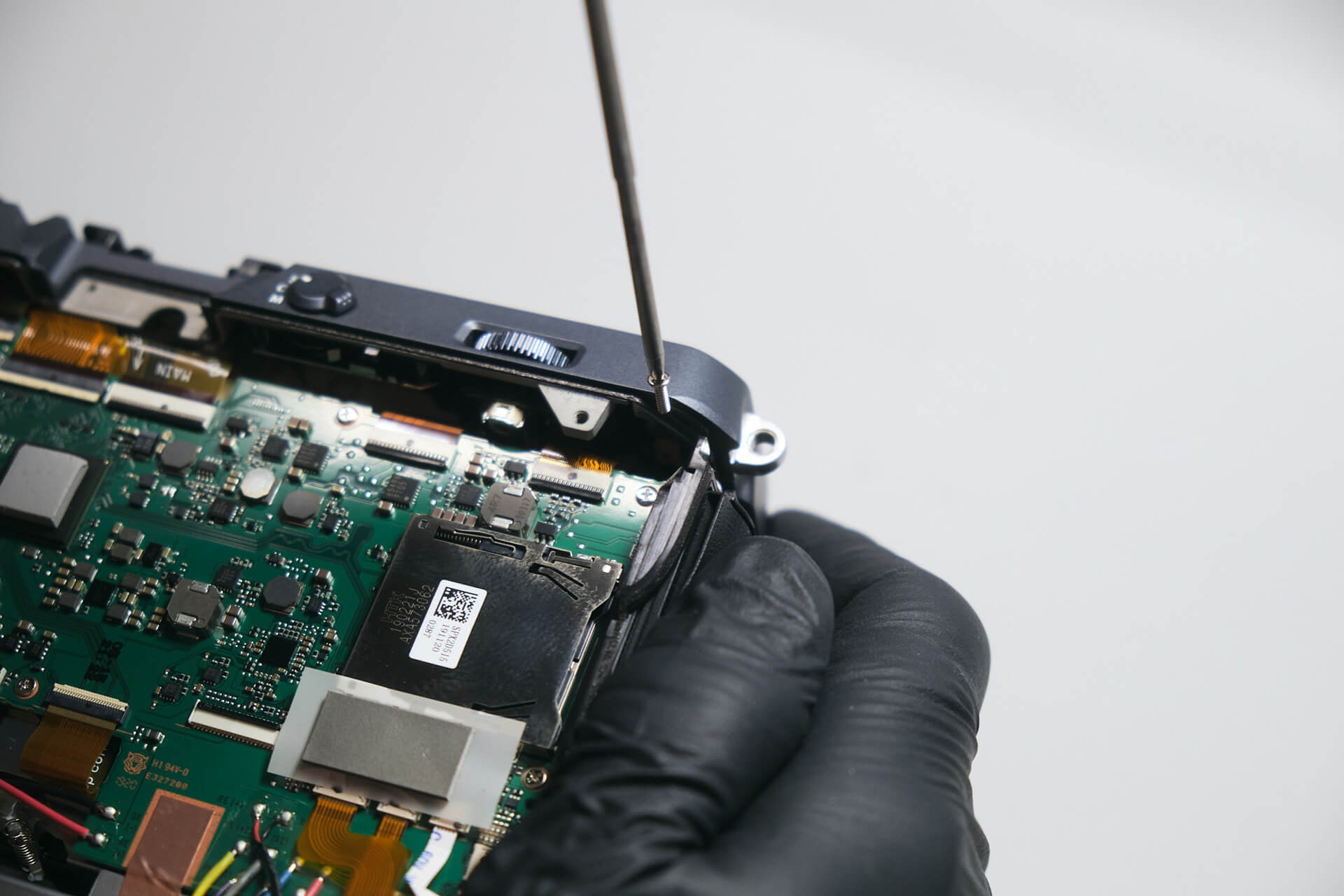
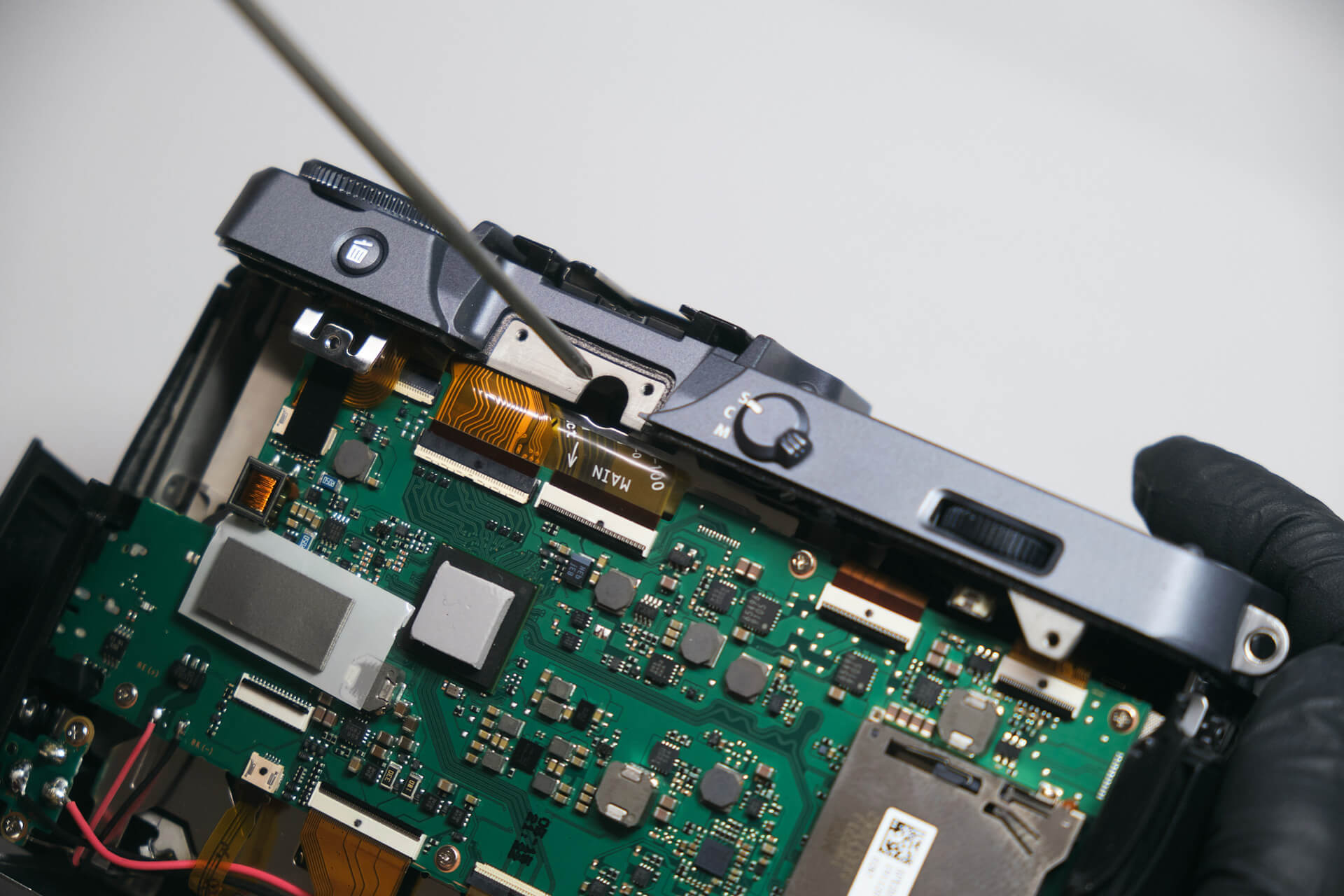
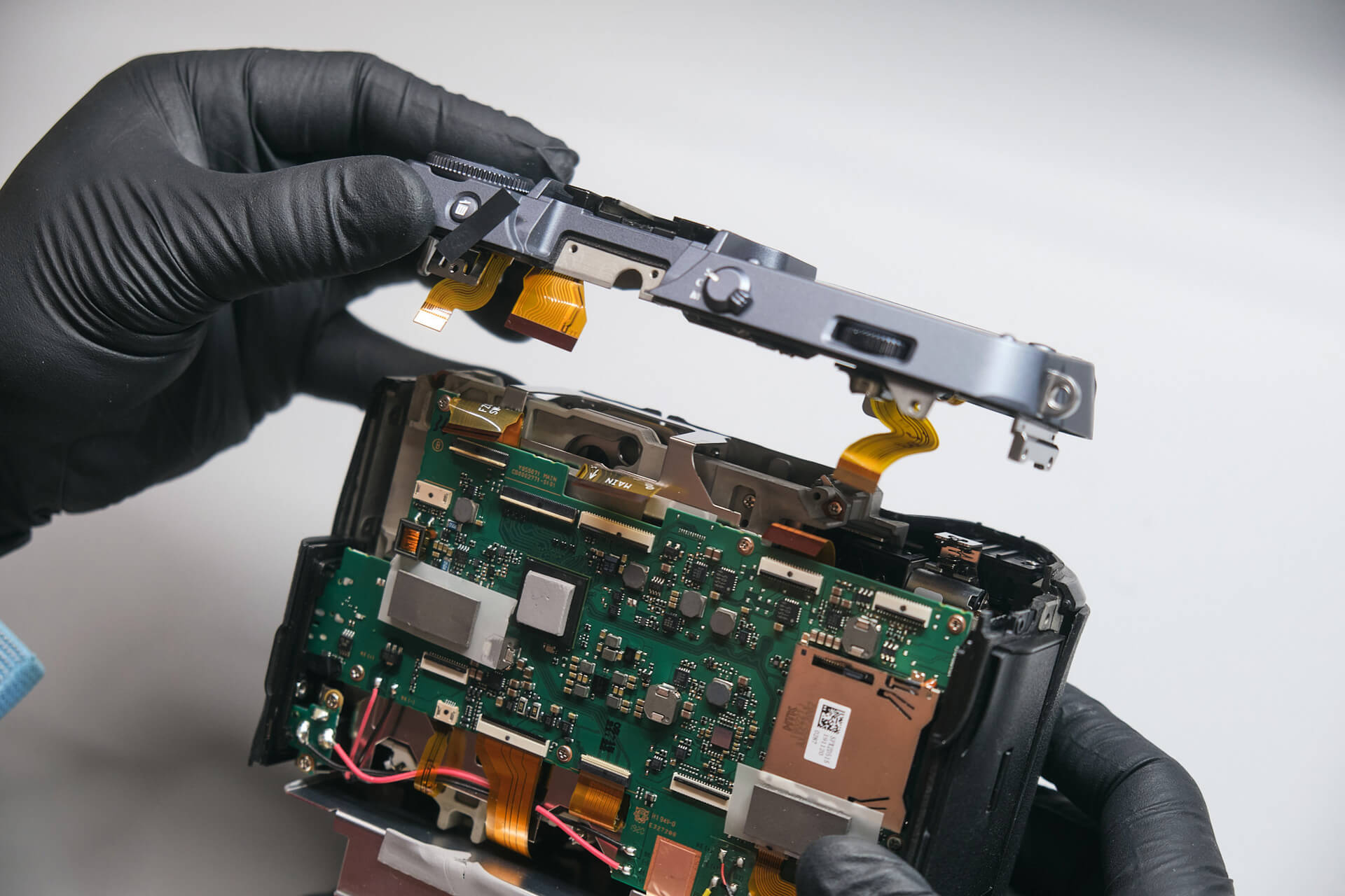
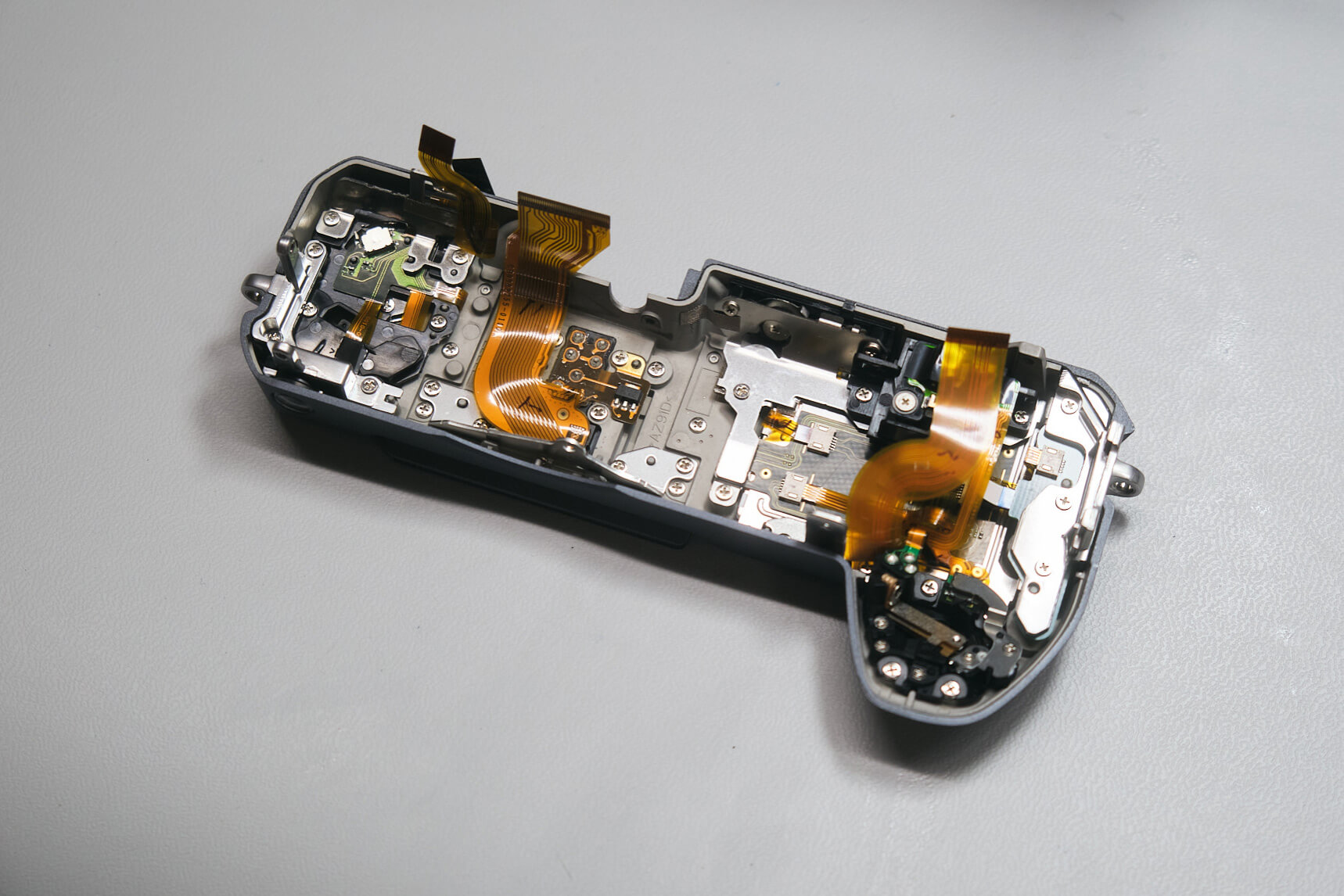
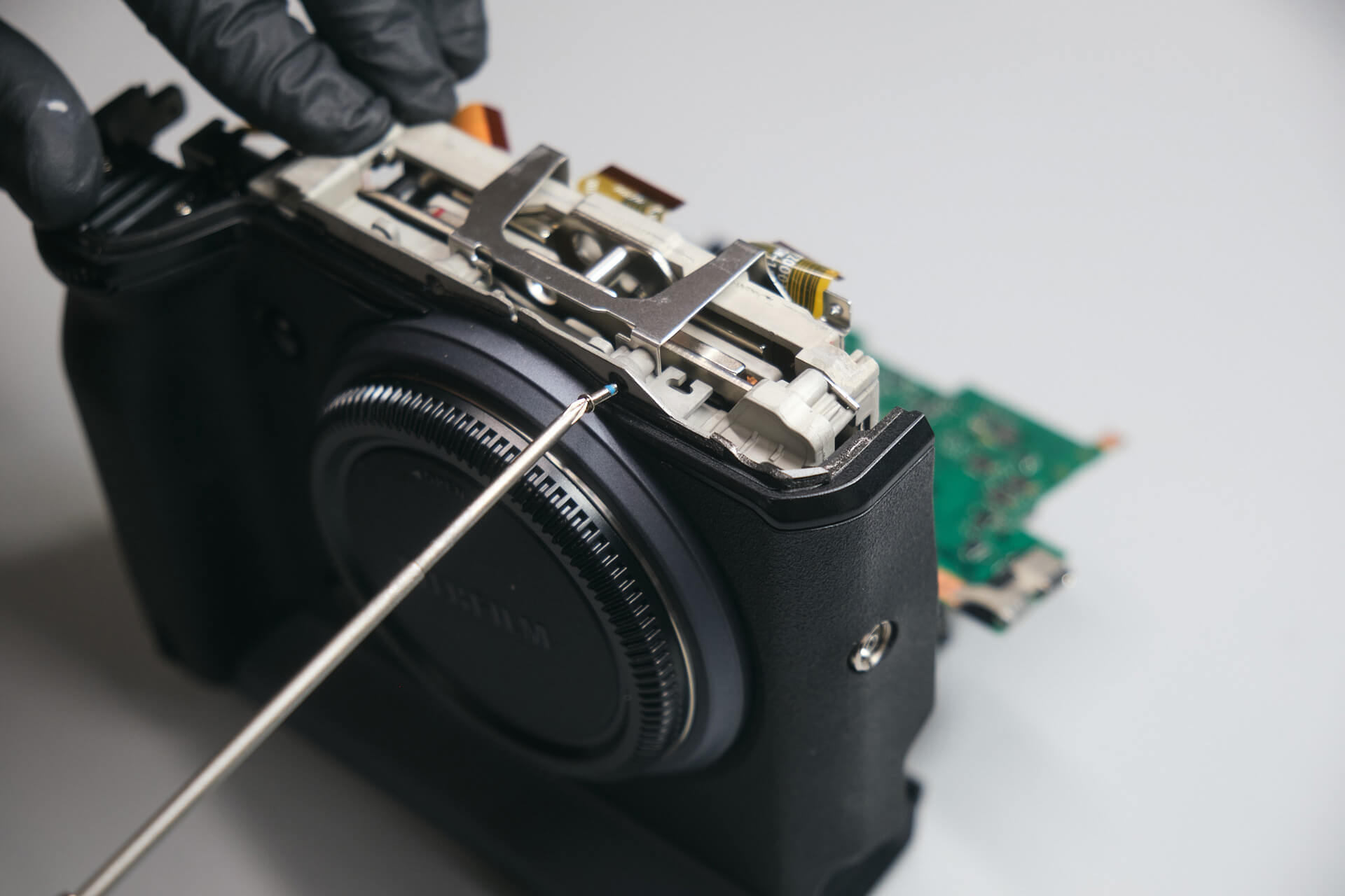
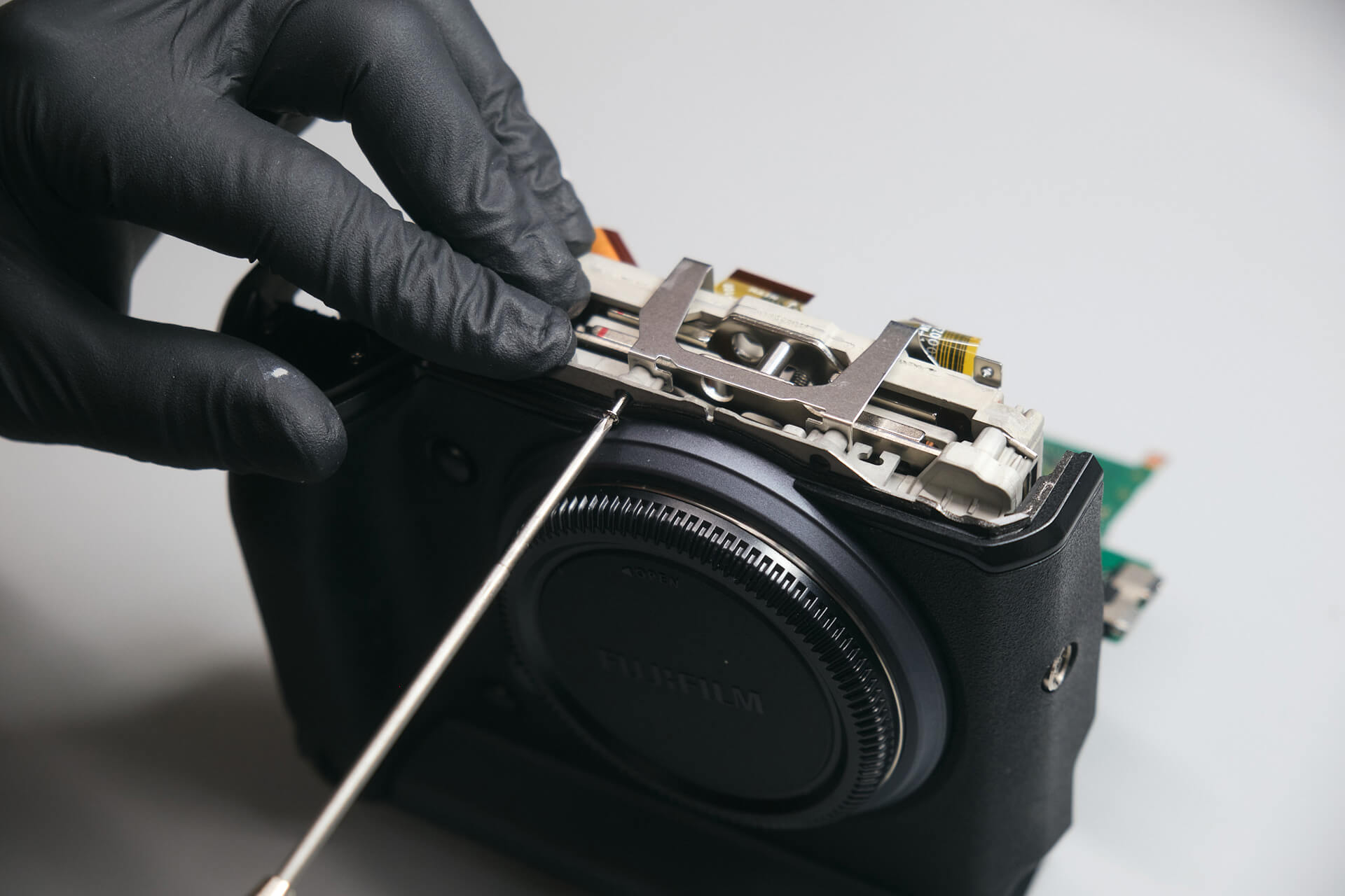
Before we could continue removing the circuit board, we needed to take off the top panel. There were hidden screws under the hot shoe, below the autofocus illuminator, and above the function button.

We found three ribbons connecting the top panel to the main circuit board. After removal, we can see that the sensor uses shims to keep it on an even plane.

Disconnecting Ribbons and Removing the Motherboard

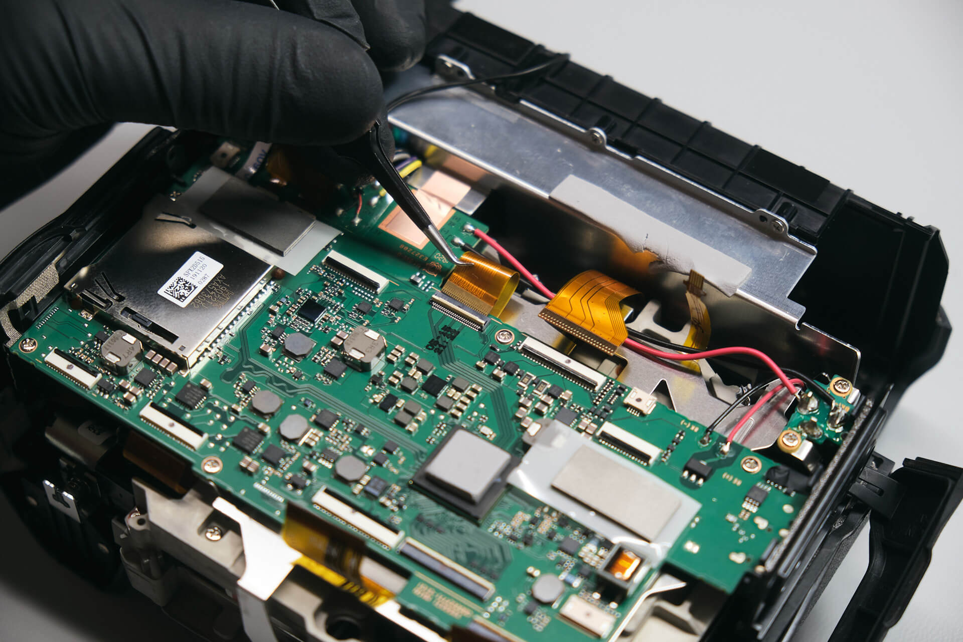
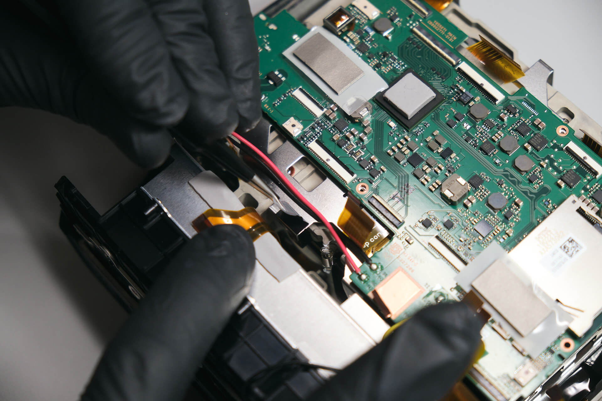
Here, we disconnected the remaining ribbons from the circuit board.

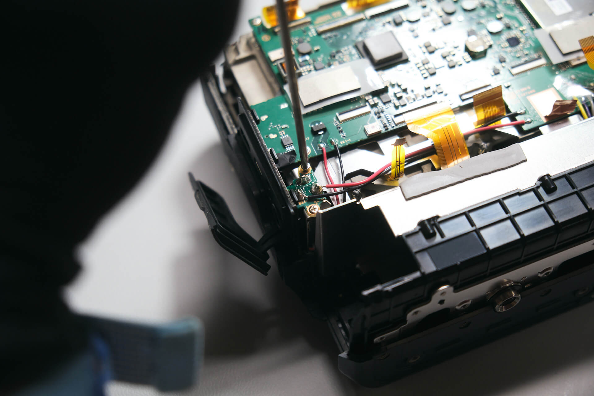
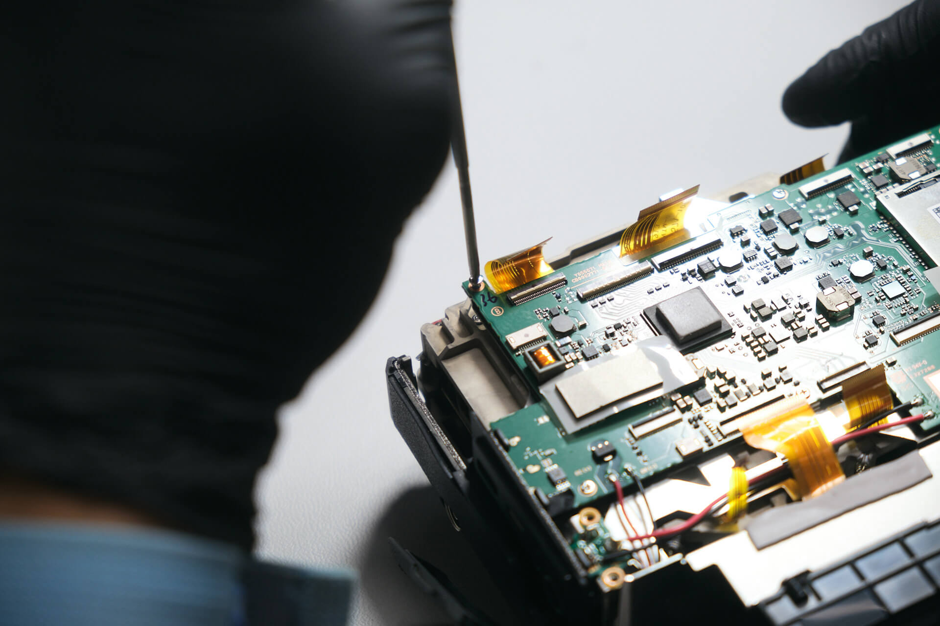
We found two screws on the 15V DC board and six screws that held down the motherboard.

With the screws removed from the board, we could remove the card reader door and port cover.

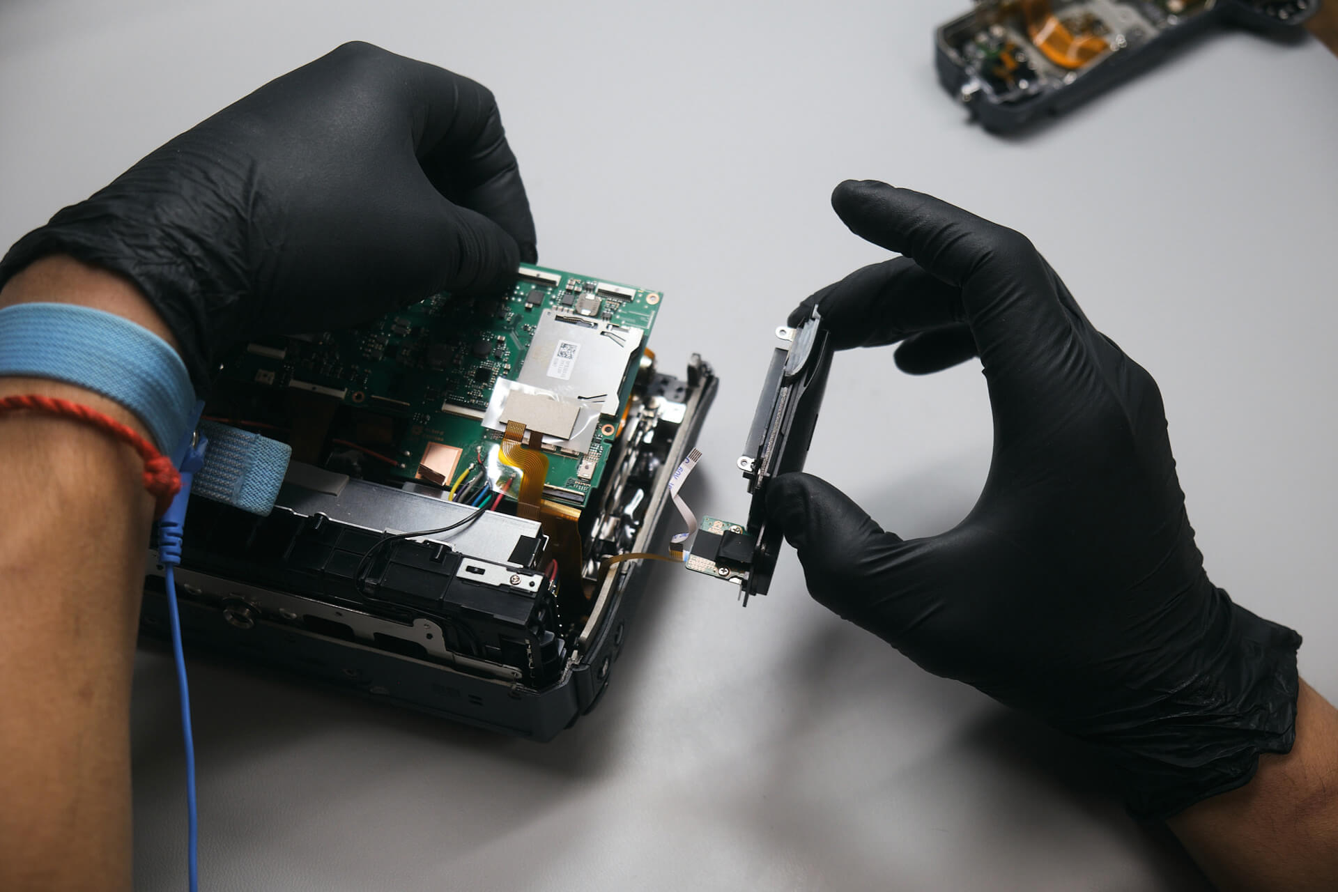
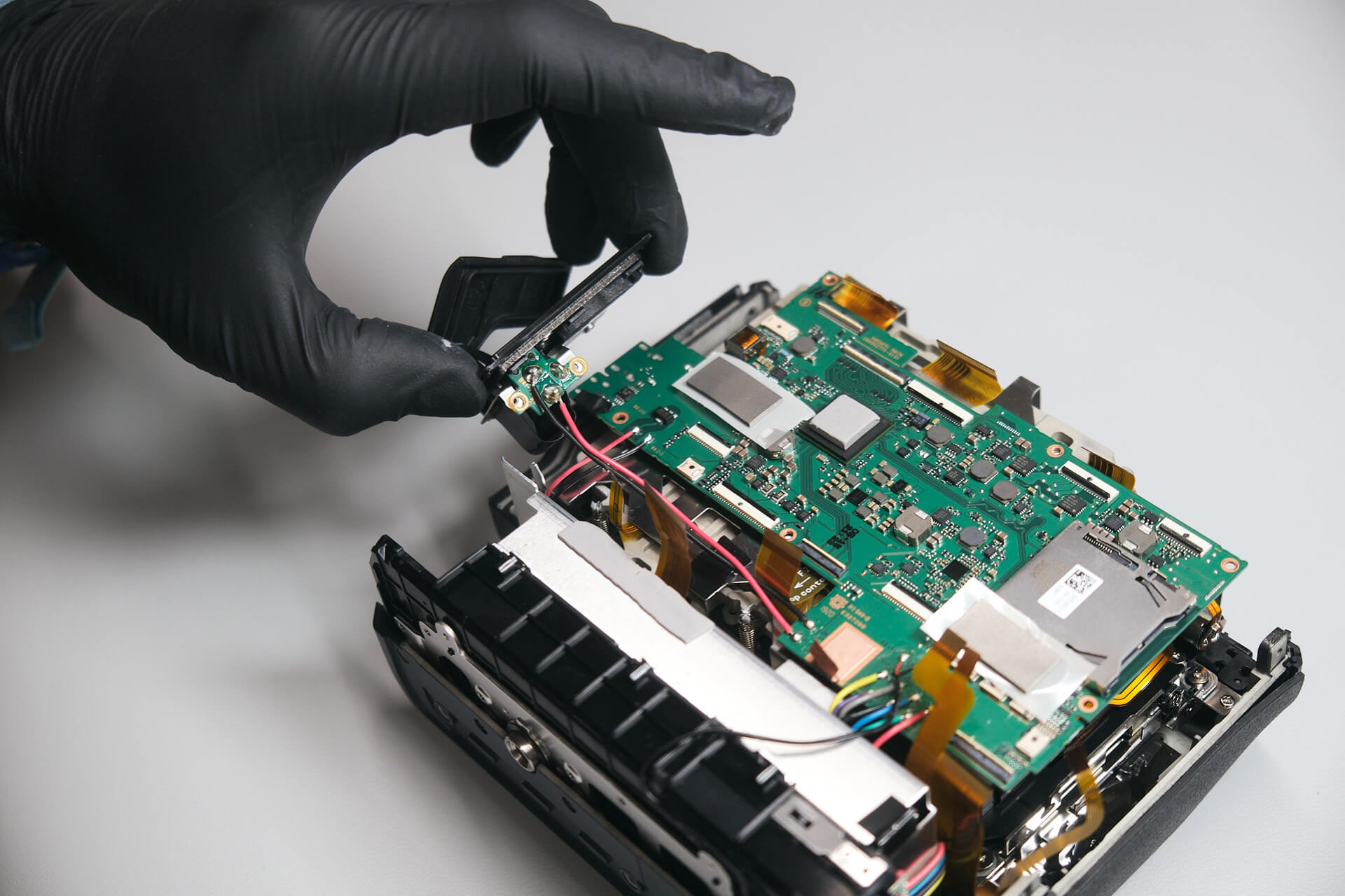
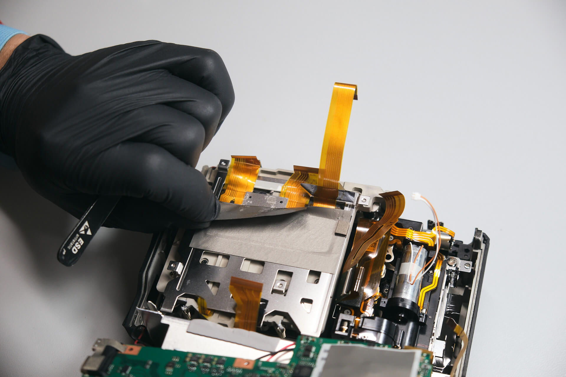
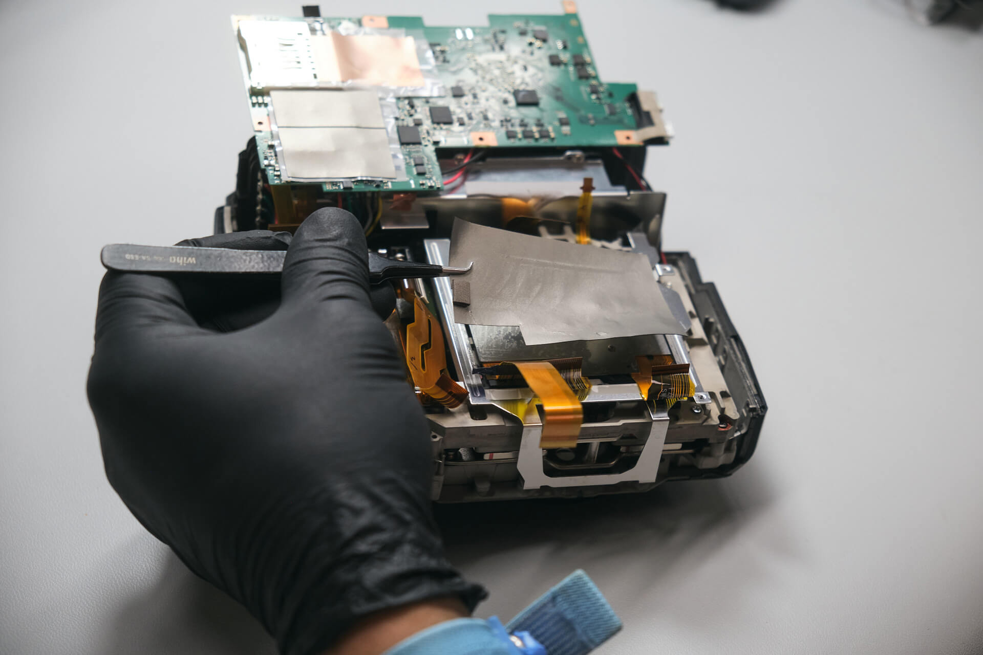
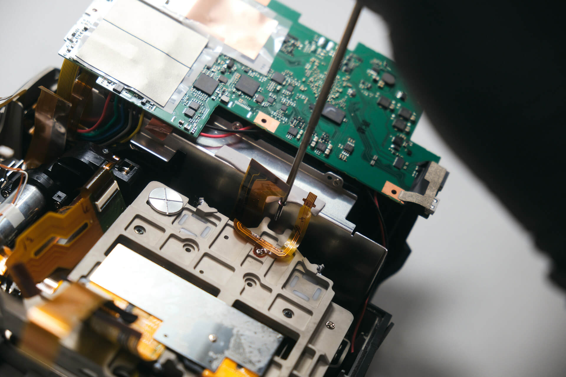
After removing the card reader door and port cover, we slightly lifted the motherboard, giving us access to peel the anti-static tape off the wires. The last static tape was actually underneath the board.

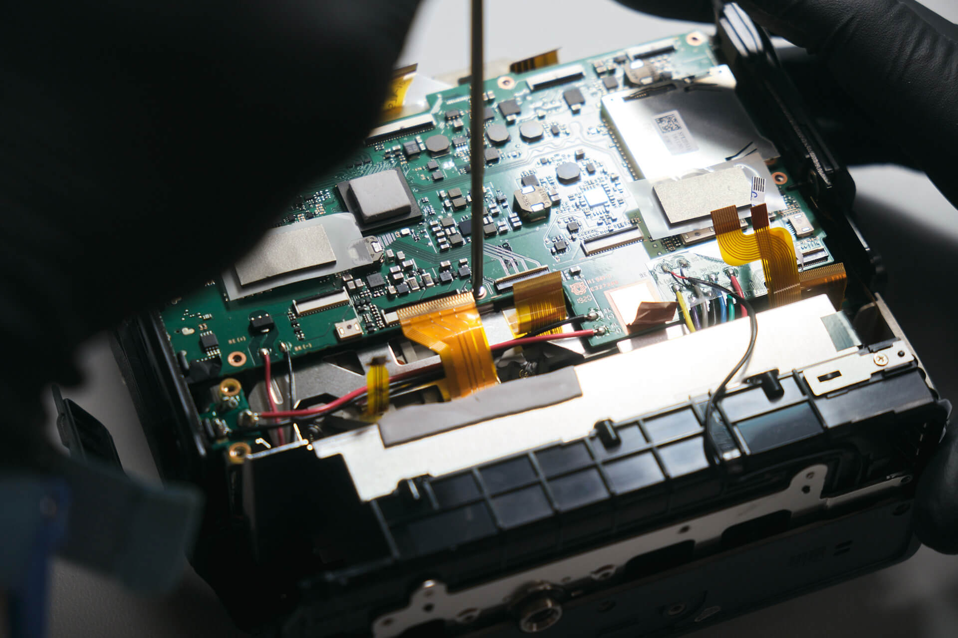
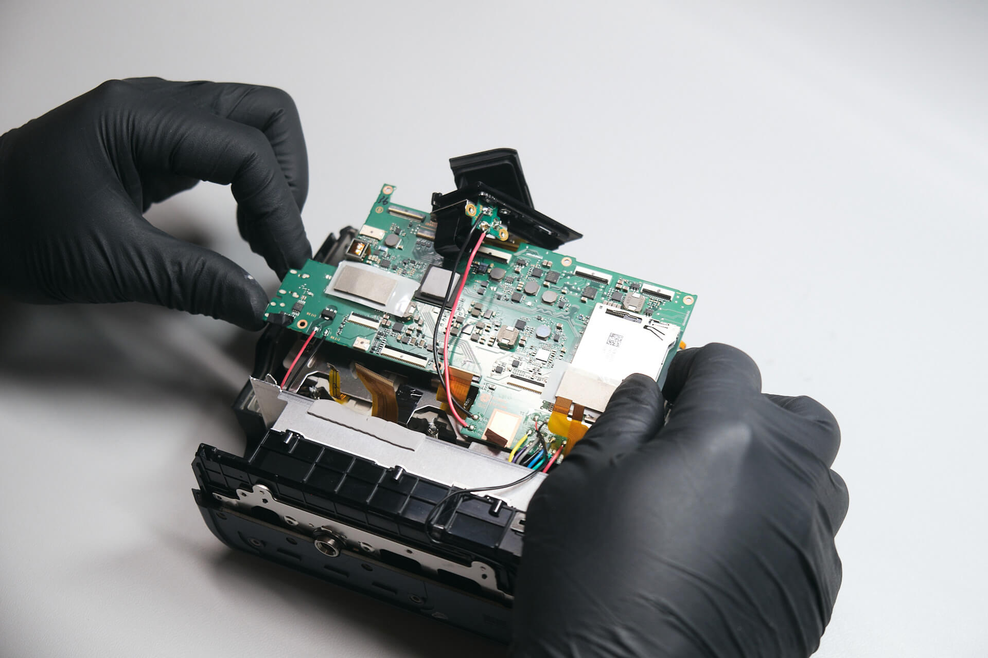
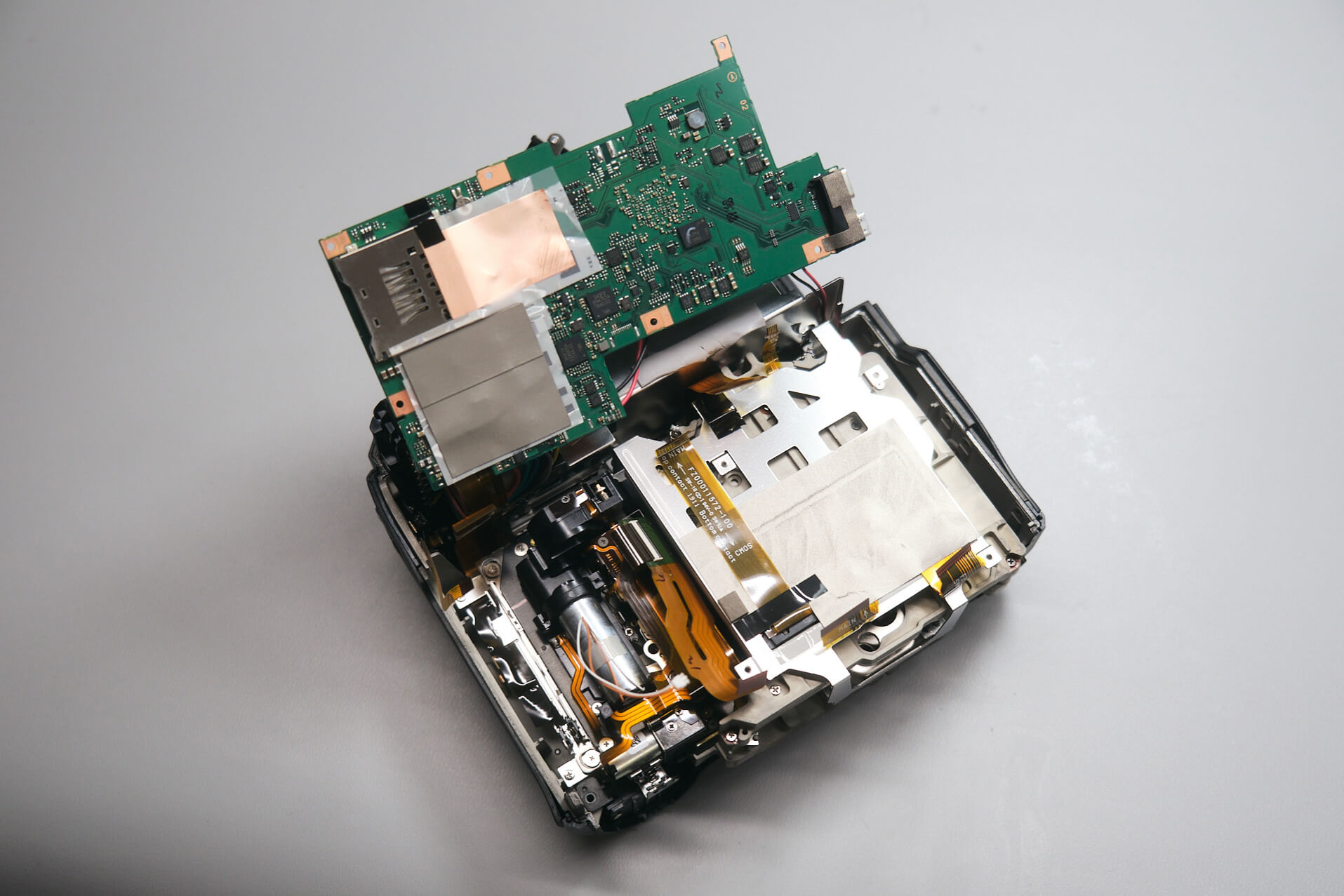
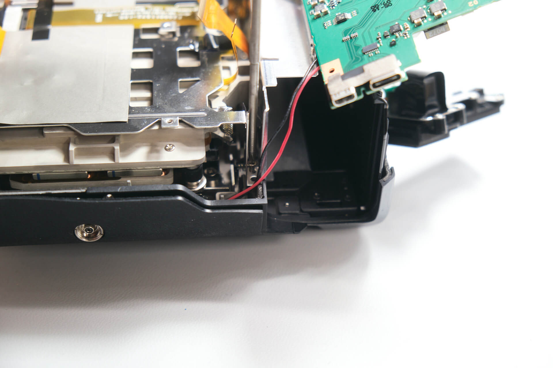
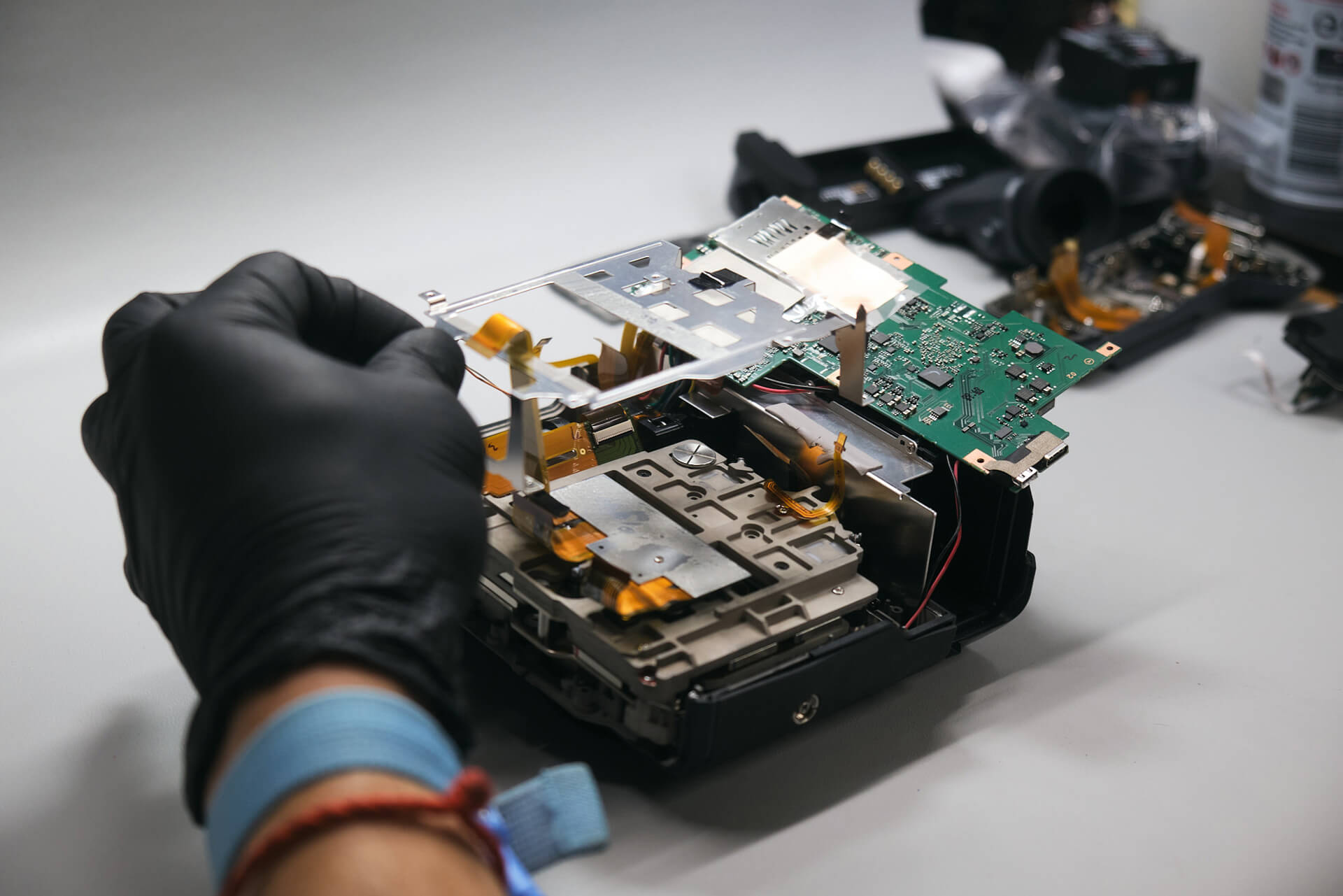
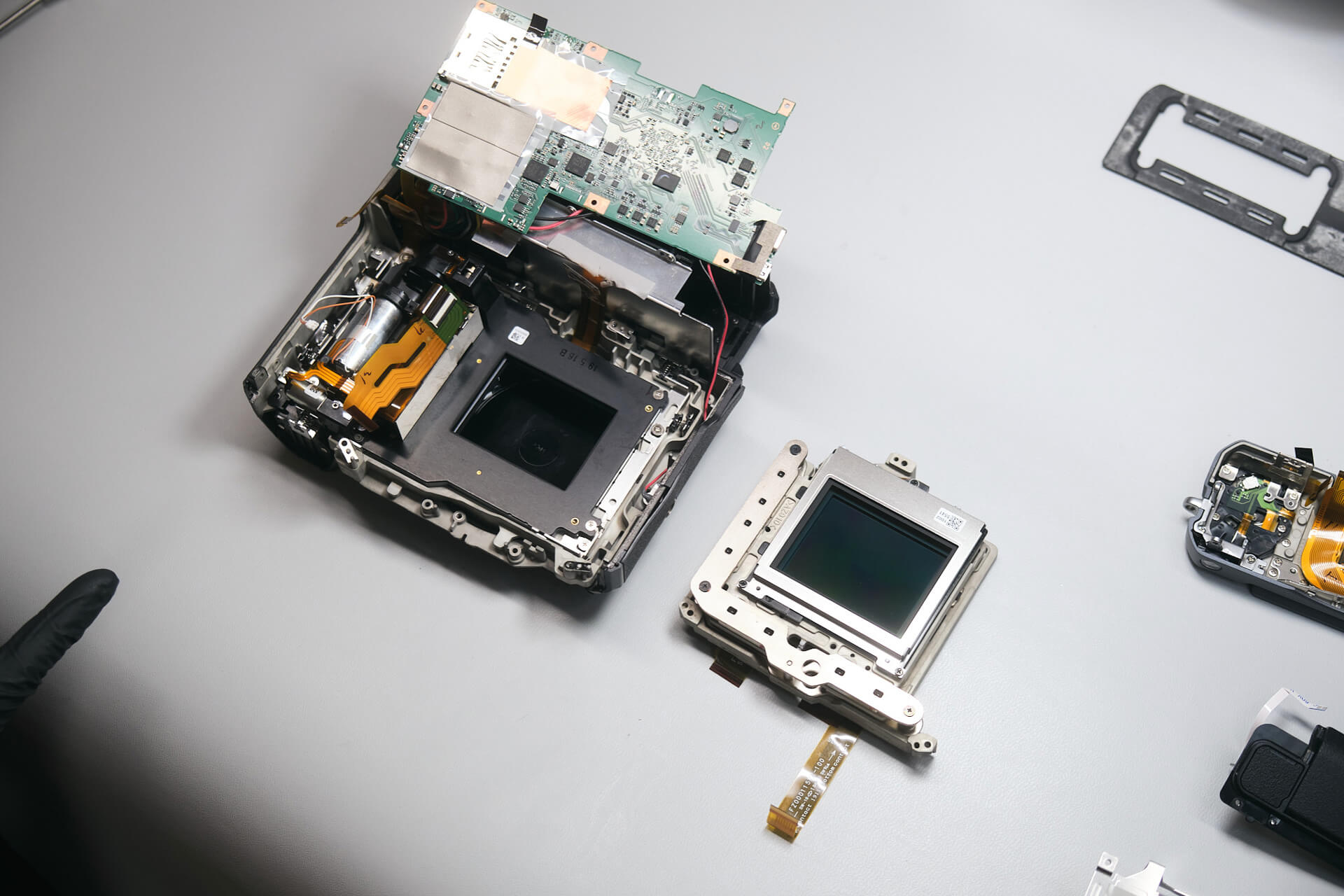
With the anti-static tape off, there was enough slack to flip the board and rest it on the battery grip housing.

Removing the Internal Bracket and Accessing the Sensor

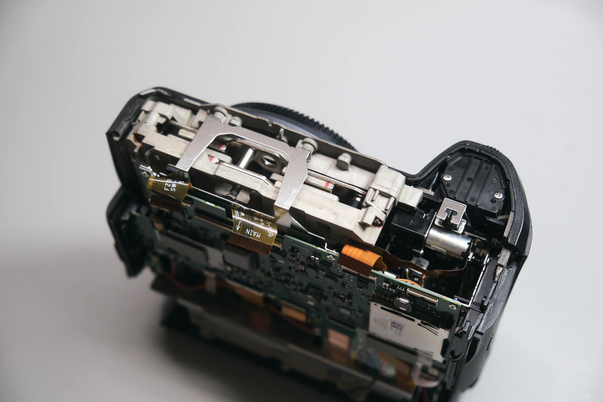
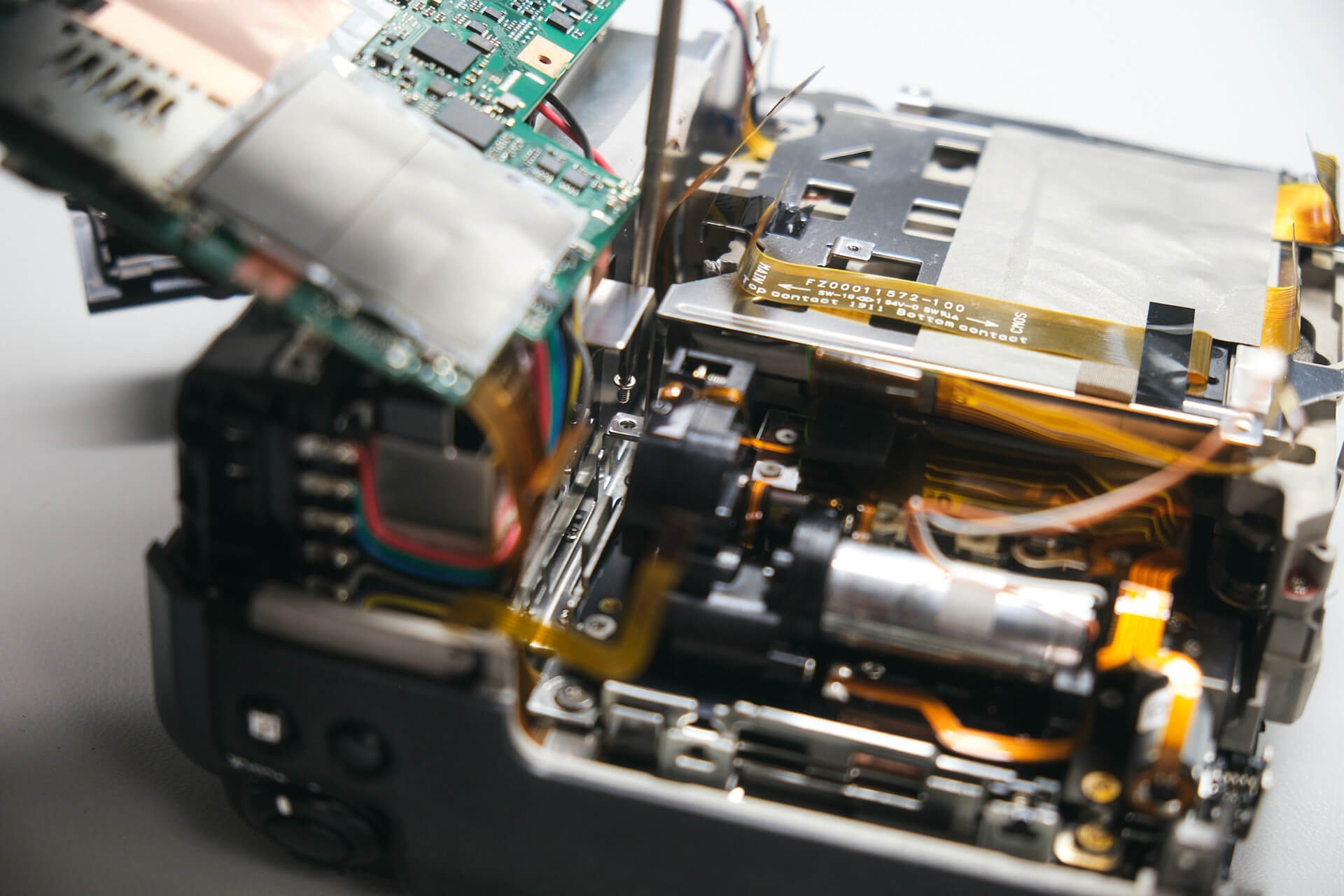
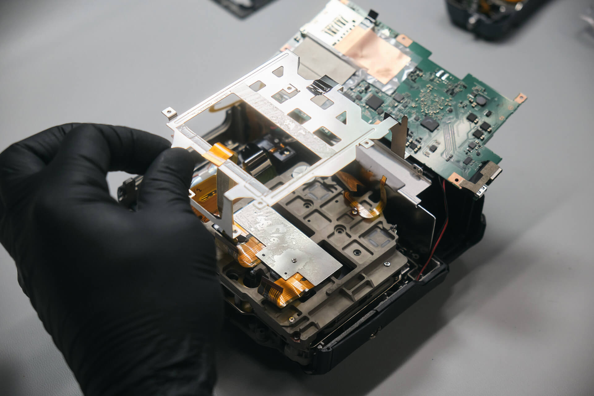
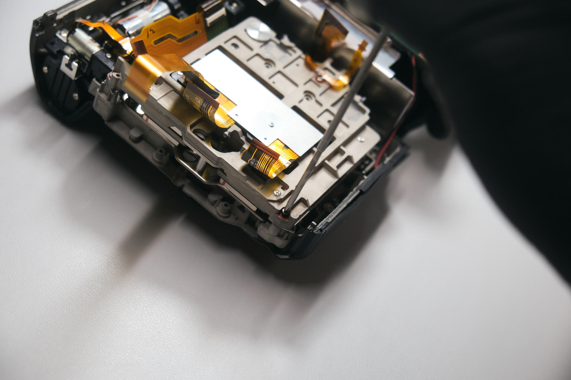
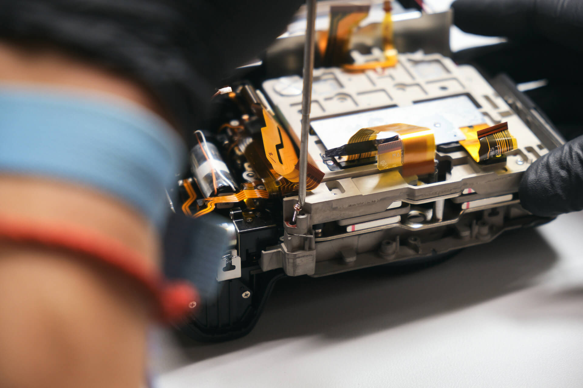
The bracket was the last layer that kept us from reaching the sensor. Four screws held down the bracket.

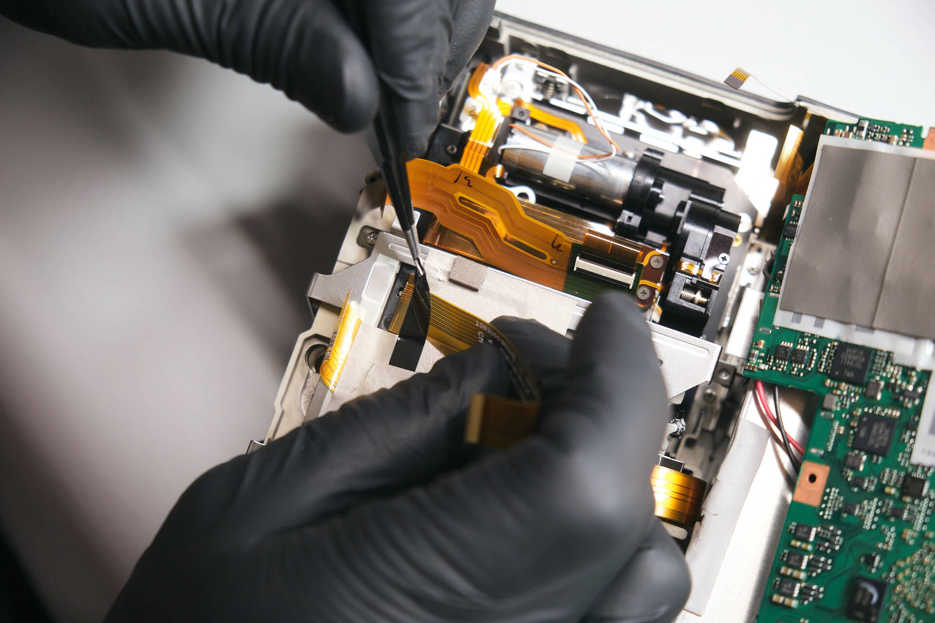
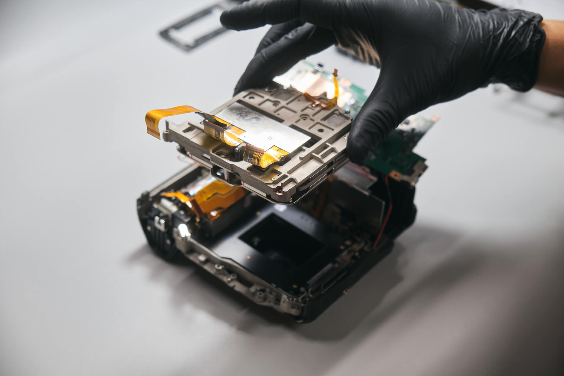
The bracket wiggled a little bit, yet it wouldn’t come off. This was because the sensor ribbons were taped onto the bracket. We had to be careful in peeling off the anti-static tape, but we were able to remove the bracket entirely once the anti-static tape was off.

Fujifilm GFX100 Sensor Removal and Final Thoughts

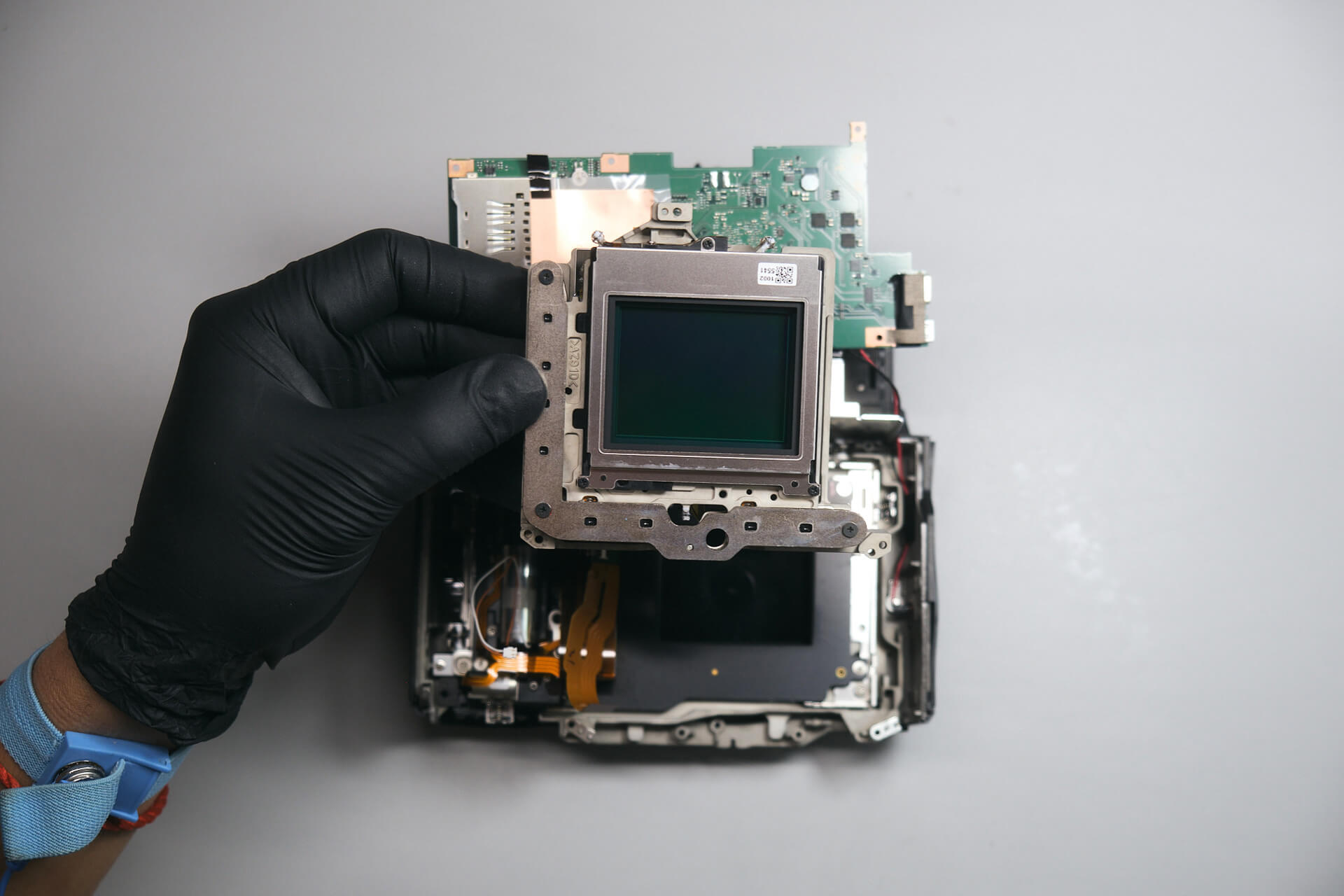
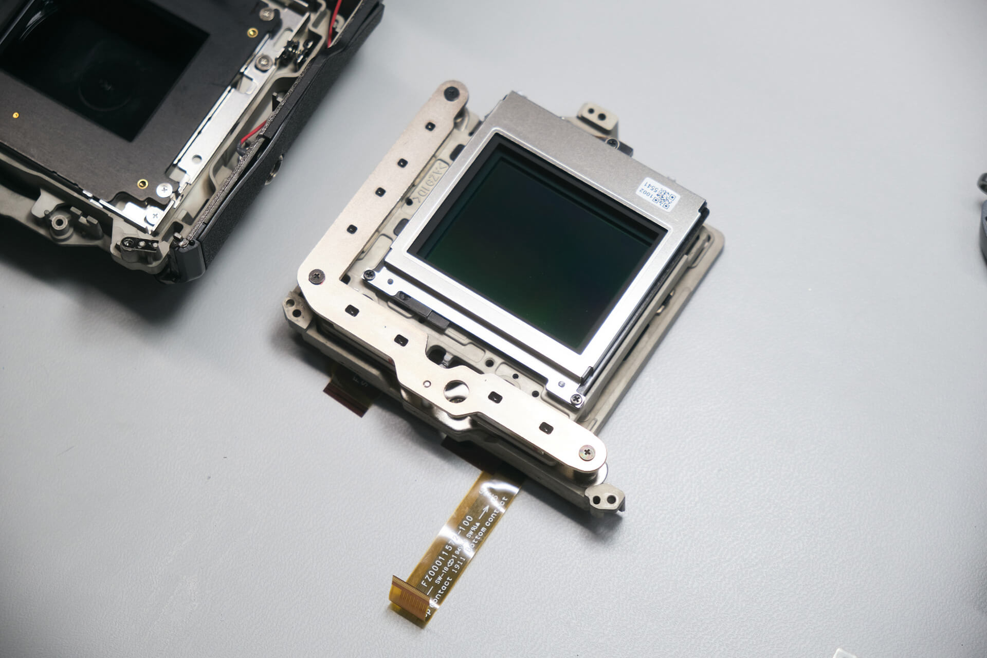
After removing the bracket, we were able to reach the sensor. Three screws held the sensor. We found that Fuji uses blue thread lock glue — this prevents the screws from moving and stripping the socket.

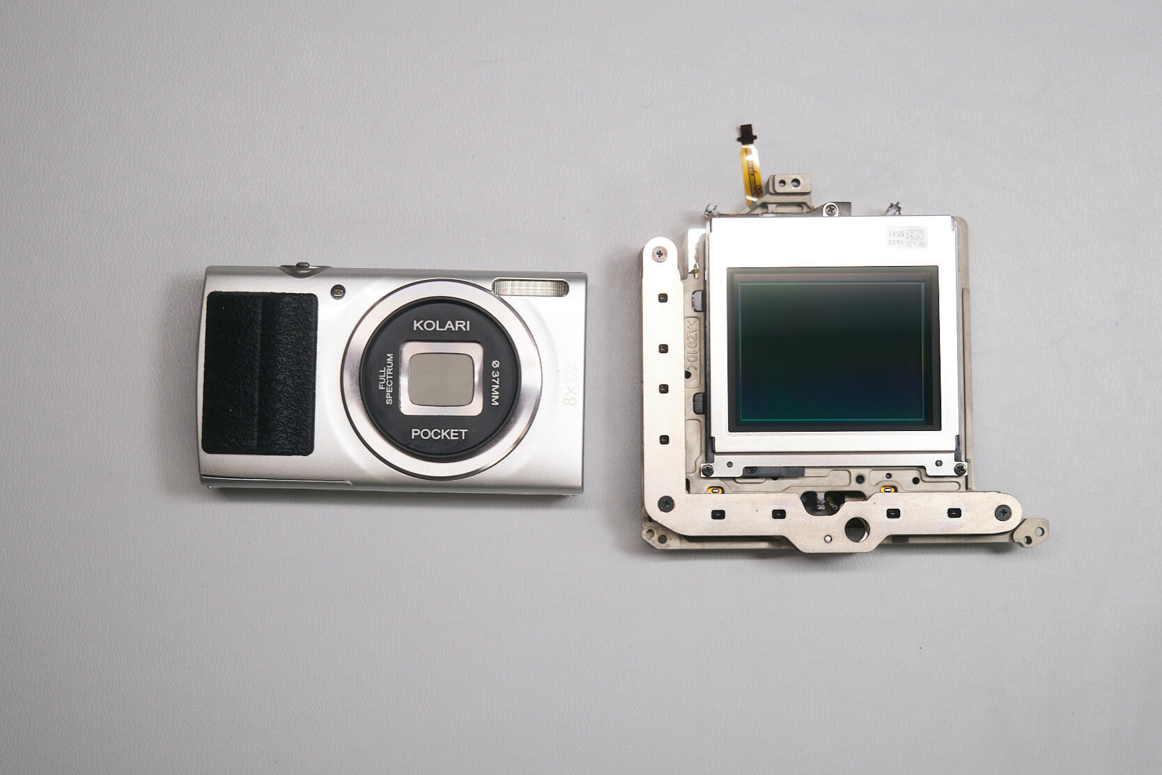
For scale reference, here is the GFX sensor assembly next to the Kolari Pocket.

The Fujifilm GFX100 was relatively easy for us to disassemble. While it was easy to take apart, the camera had many screws to keep track of, according to our camera technician Jared.

Thanks for reading. If you’re interested in more camera teardowns, we feature a new one every month. Be sure to sign up for our newsletter so you don’t miss them!

Frequently Asked Questions

The Fujifilm GFX100 teardown starts by removing external peripherals from the camera body, including the detachable OLED viewfinder and battery tray. After that, the teardown moves into hidden screws around the LCD monitor, rubber grips, port side, card door, and baseplate.

The Fujifilm GFX100 has several hidden screws under the LCD monitor, rubber grips, SD card door area, rear command dial area, hot shoe, autofocus illuminator area, and function button area. These hidden screws need to be removed before the body panels and top panel can come off.

The rear panel can be lifted after the exterior screws and hidden grip screws are removed. Before the back panel can fully separate, the LCD and rear button ribbon cables need to be disconnected from the circuit board.

The Fujifilm GFX100 motherboard is removed after the top panel, remaining ribbon cables, 15V DC board screws, motherboard screws, card reader door, port cover, and anti-static tape are handled. Once the anti-static tape is peeled back, the board can be lifted and flipped with enough slack.
The sensor is reached after the motherboard and internal bracket are removed. The bracket is held by four screws and sensor ribbons taped onto it. After the tape and bracket are removed, the sensor can be accessed, and three screws hold the sensor in place.
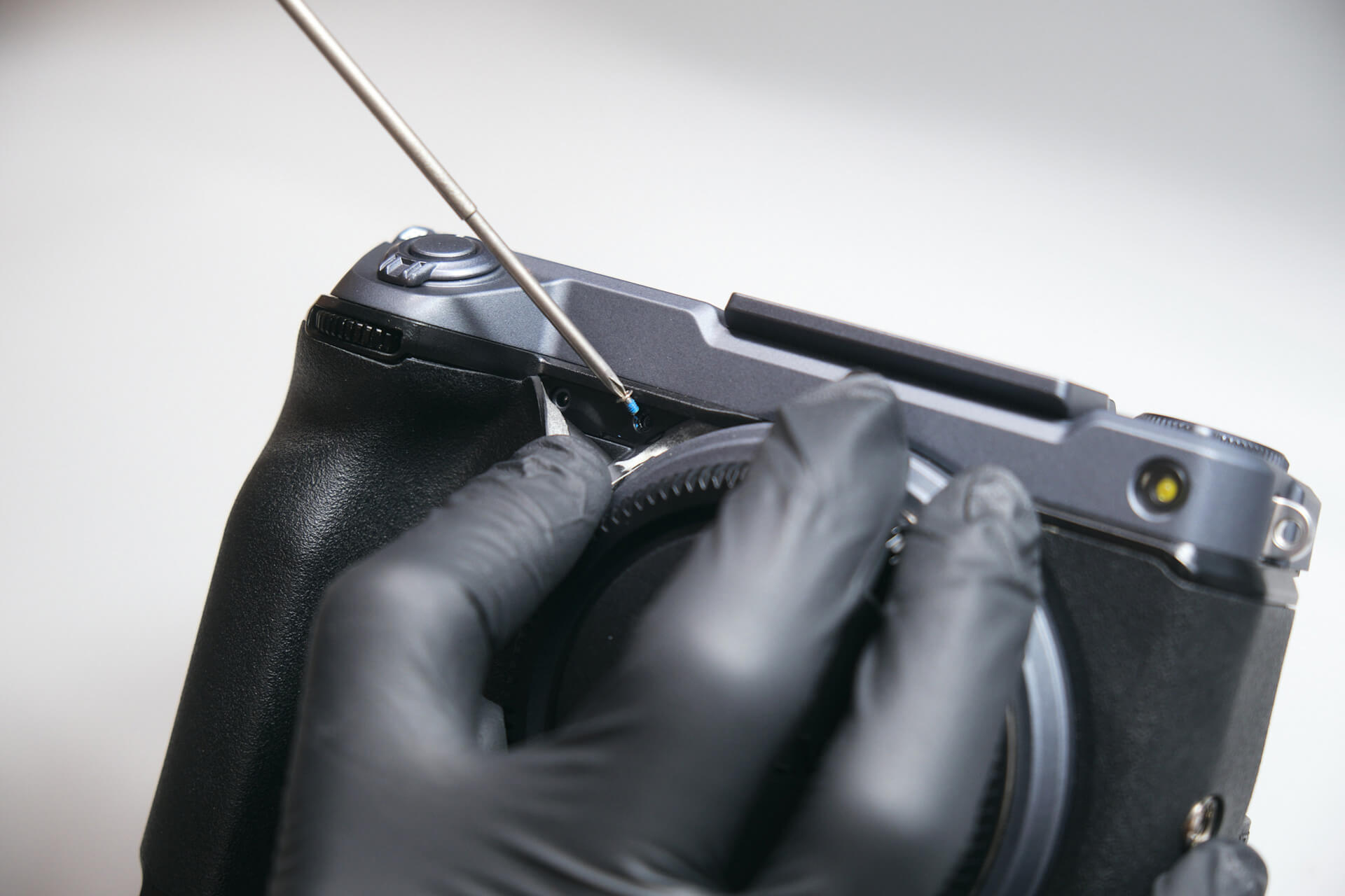
Table of contents
Related Article

Product Spotlight

Comments

Leave a Reply

Your email address will not be published. Required fields are marked *

Related products

Kolari’s EU store
is now open! 

Filters and accessories now shipping from Slovenia with VAT included and quick DHL shipping.
kolaris-eu-store_is-now-open
Skip to content