Canon EOS R5C Camera Overview and RF-Mount Compatibility
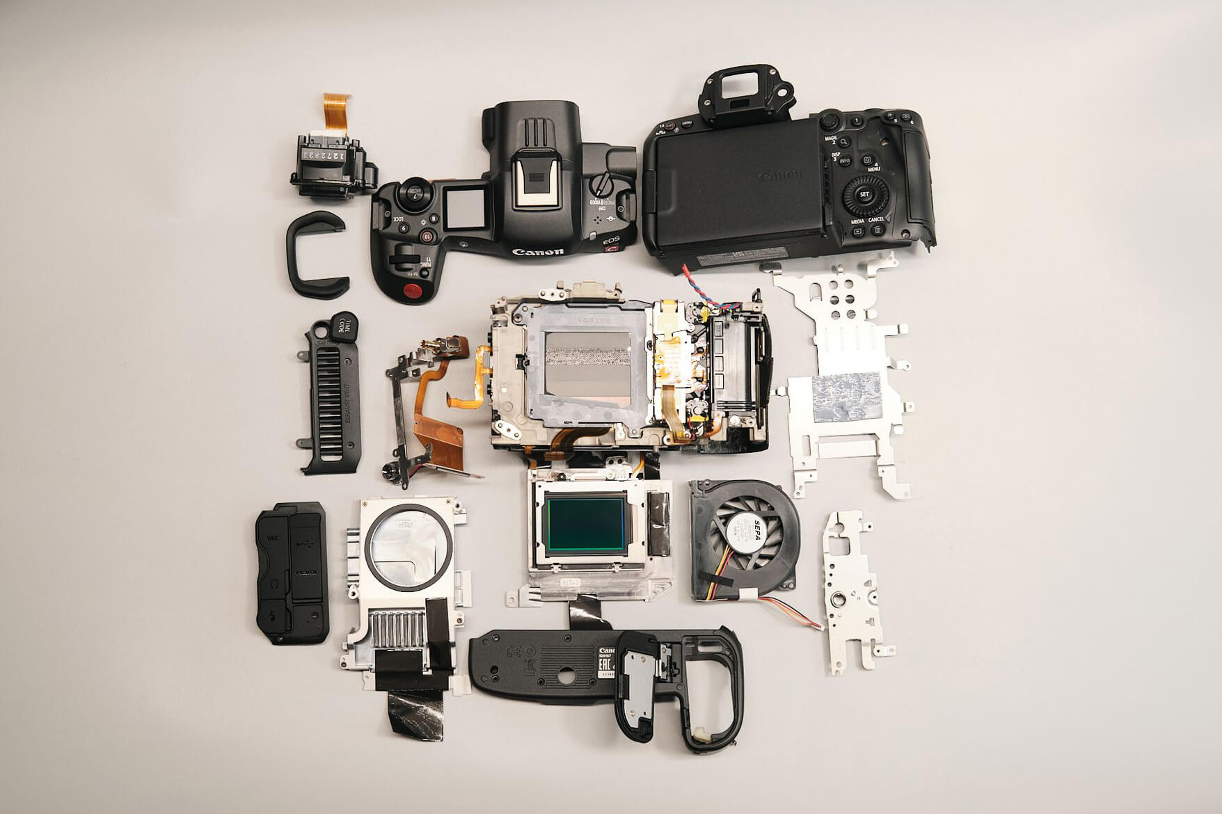
Canon announced the Canon EOS R5C a little less than a year ago (March 2022), and we were fortunate enough to get our hands on one for a teardown here at Kolari. How different (or similar) is this camera compared to its predecessor, the Canon EOS R5 (released in July 2020)? Before we get into our teardown, let’s first talk about technical specifications.
While the Canon EOS R5C didn’t make the cut for Netflix’s production certification, it still boasts hefty features fit for a cinema camera that puts it a mark above the competition. Its main highlight is its core: an impressive full-frame 45MP 8K sensor and DIGIC X Processor with 8K and 2K sampling that supports 8K in many platforms, including Internal RAW/Cinema RAW Light Recording. Thanks to the built-in fan, it’s capable of non-stop recording in 8K/60p. Overall, it improves on its previous iteration with better autofocus, sensor and viewfinder resolution, and ISO performance, among other features.
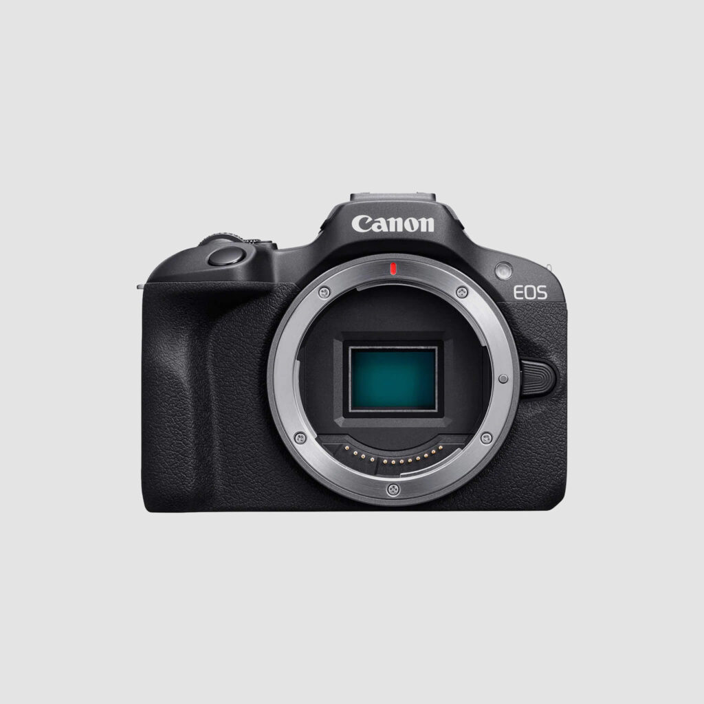
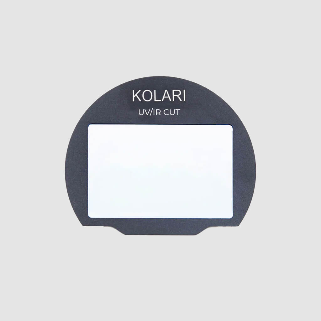
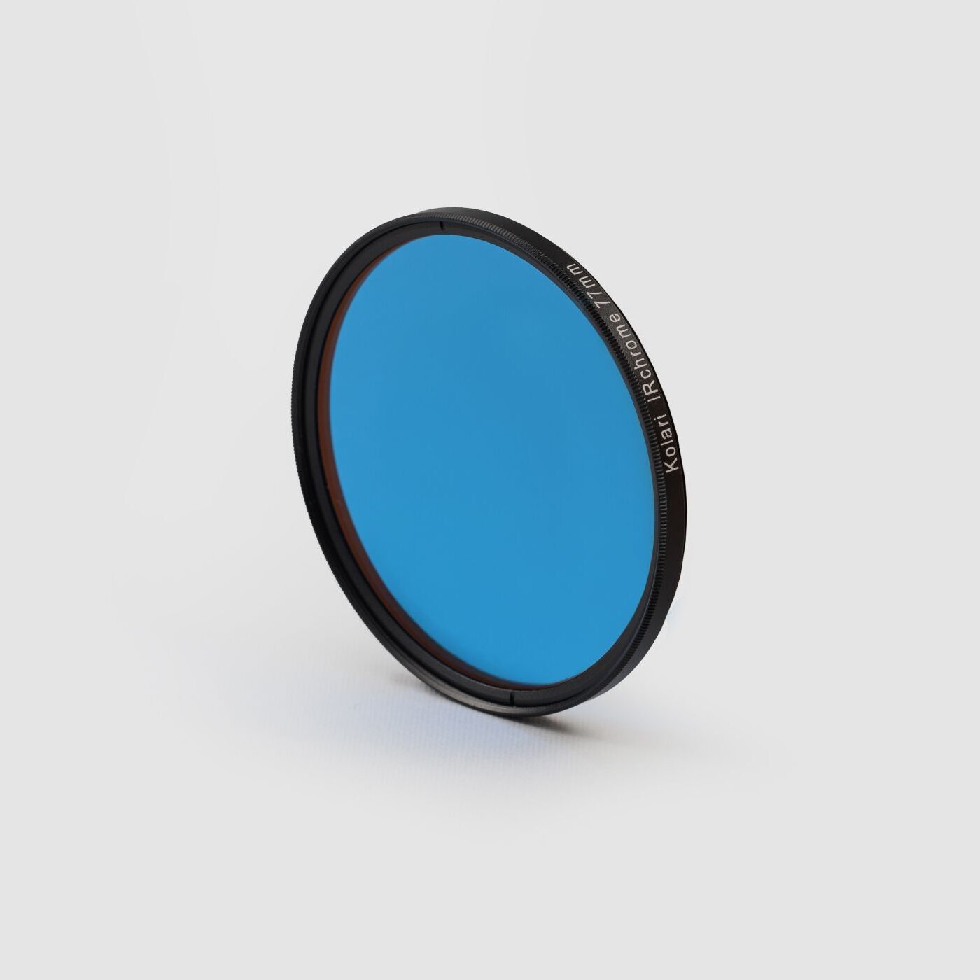
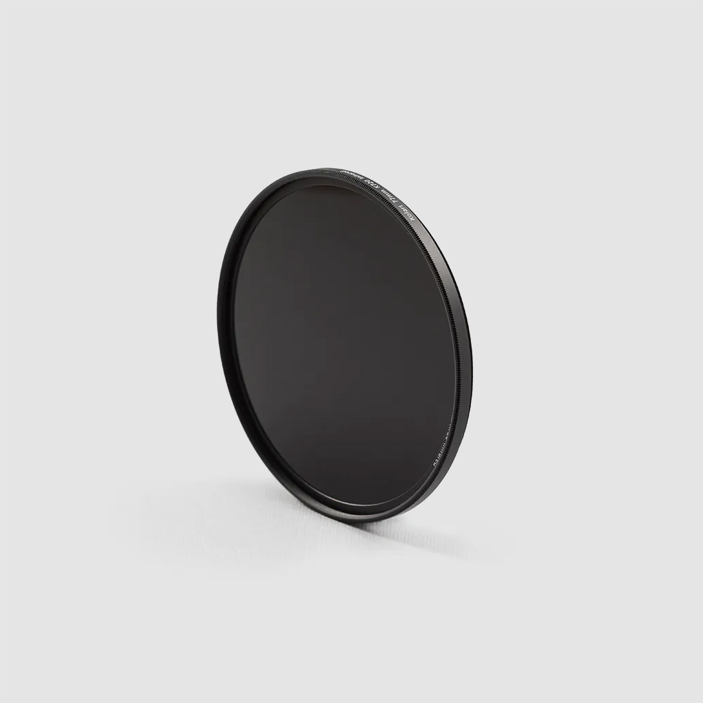
The camera also uses an RF-mount, which is compatible with our magnetic clip-in filters; it also accepts an EF-EOS R Mount Adapter for compatibility with our drop-in filters.
With that out of the way, let’s talk about disassembling this camera!
Starting the Canon R5C Teardown
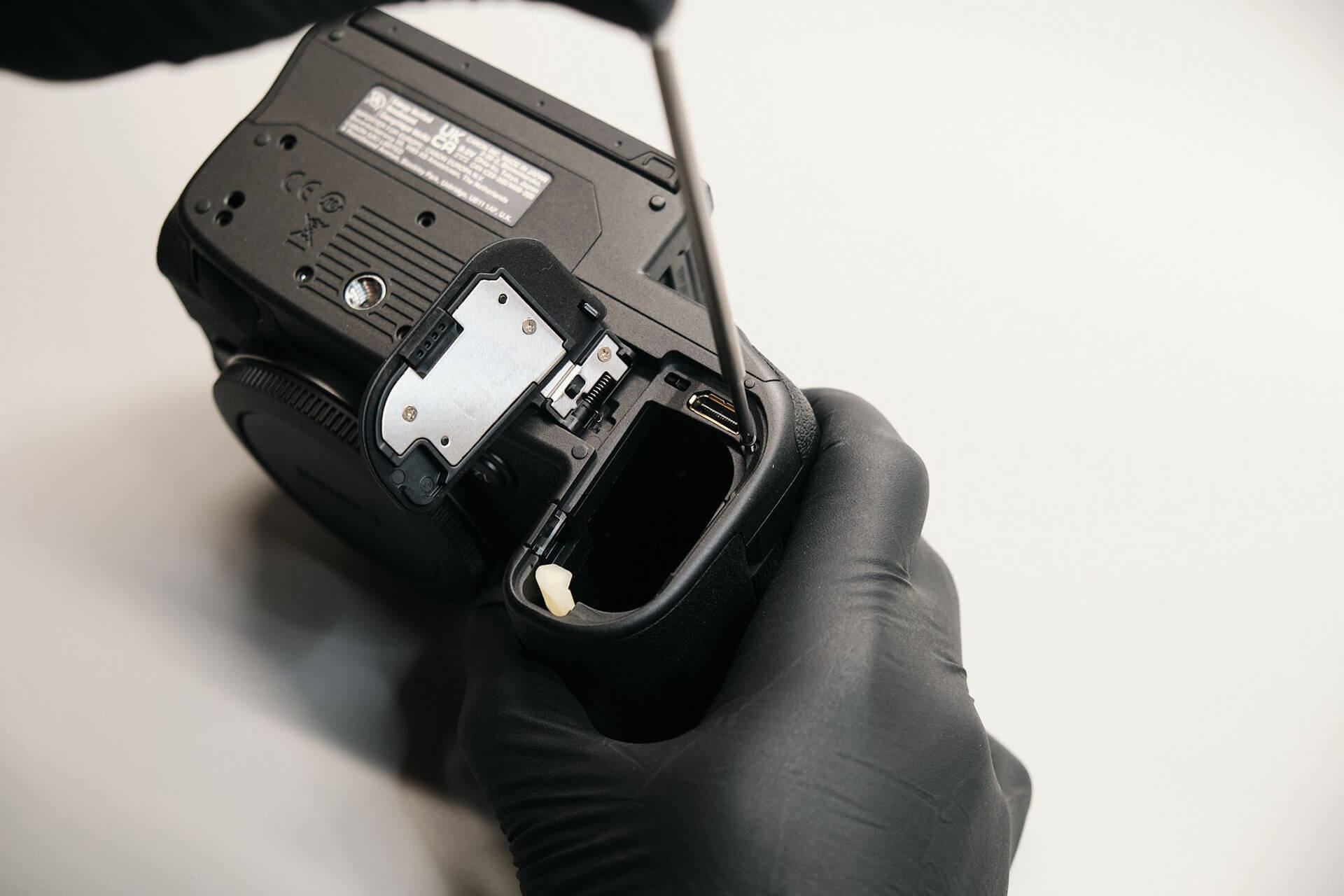
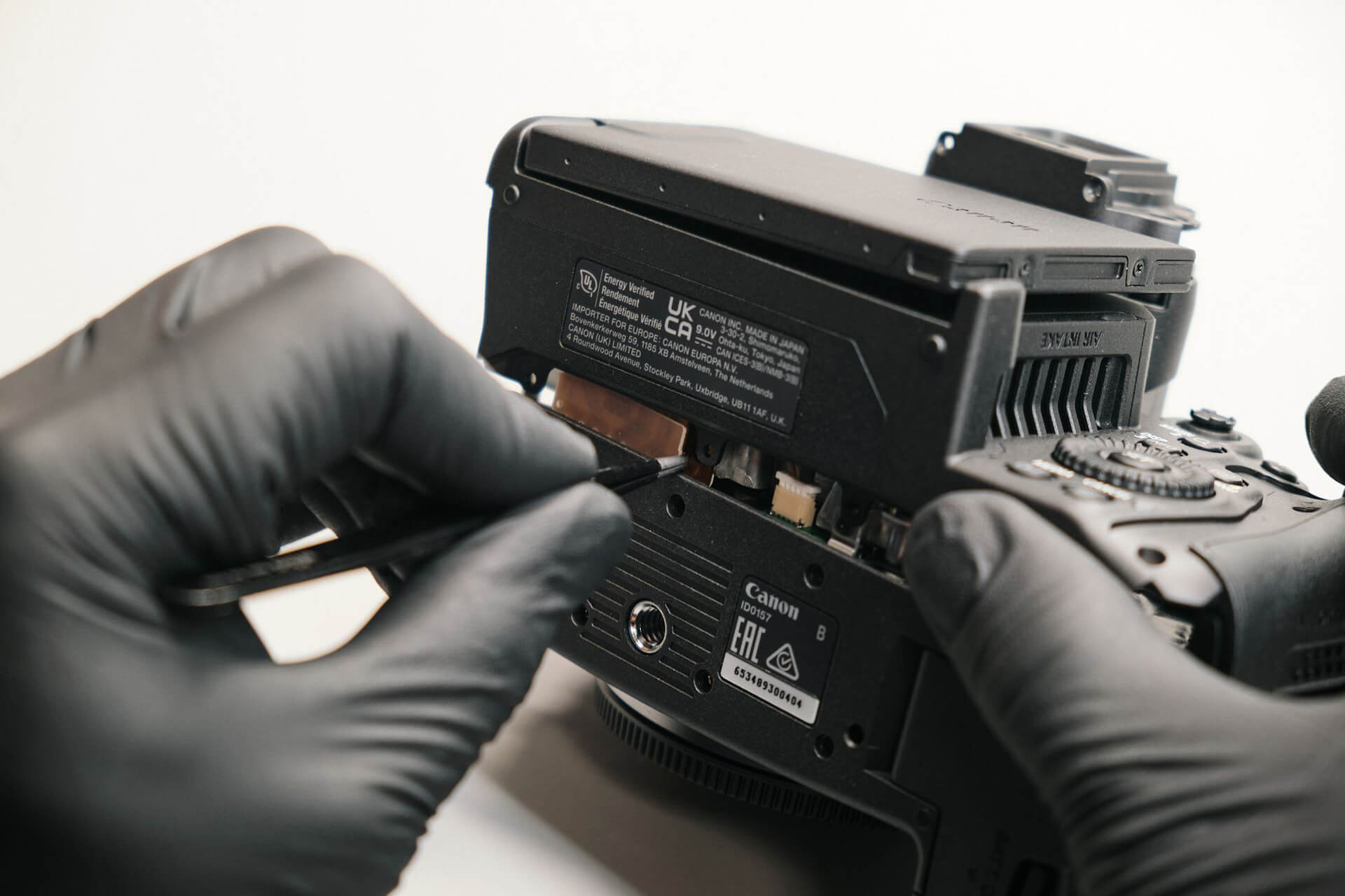
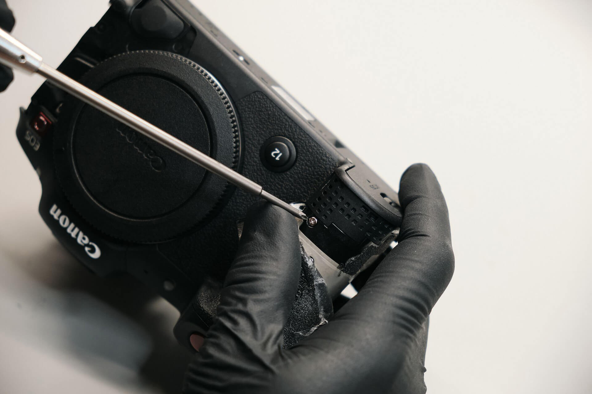
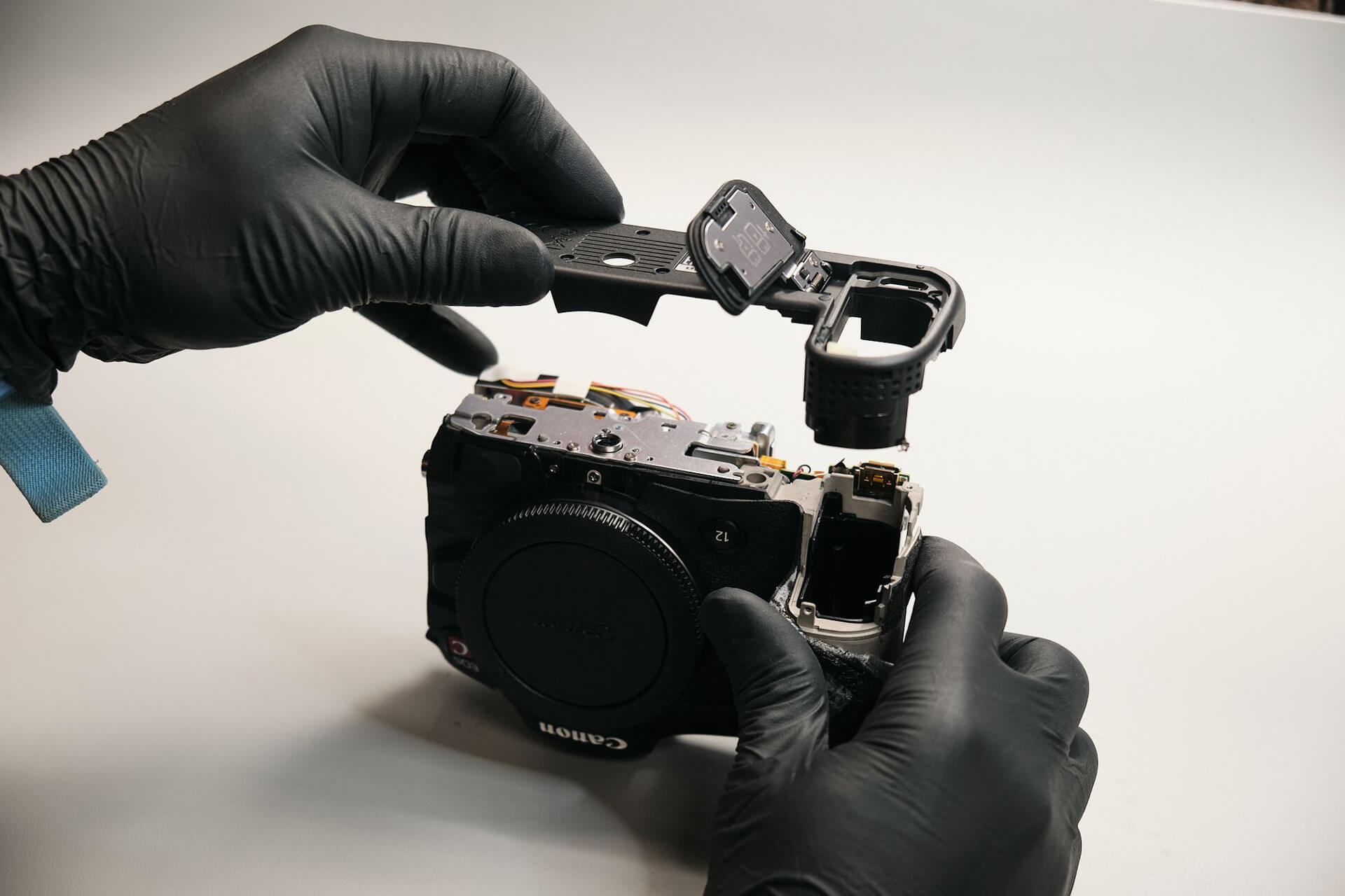
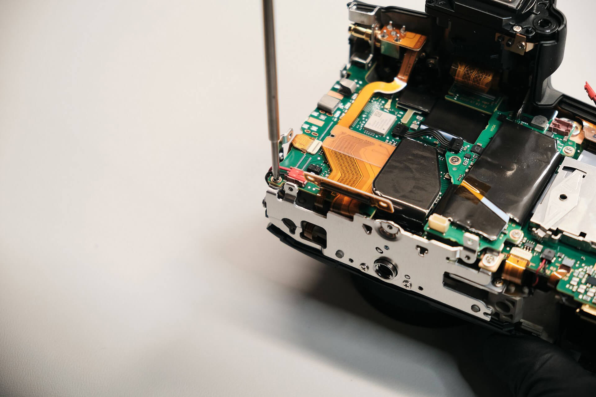
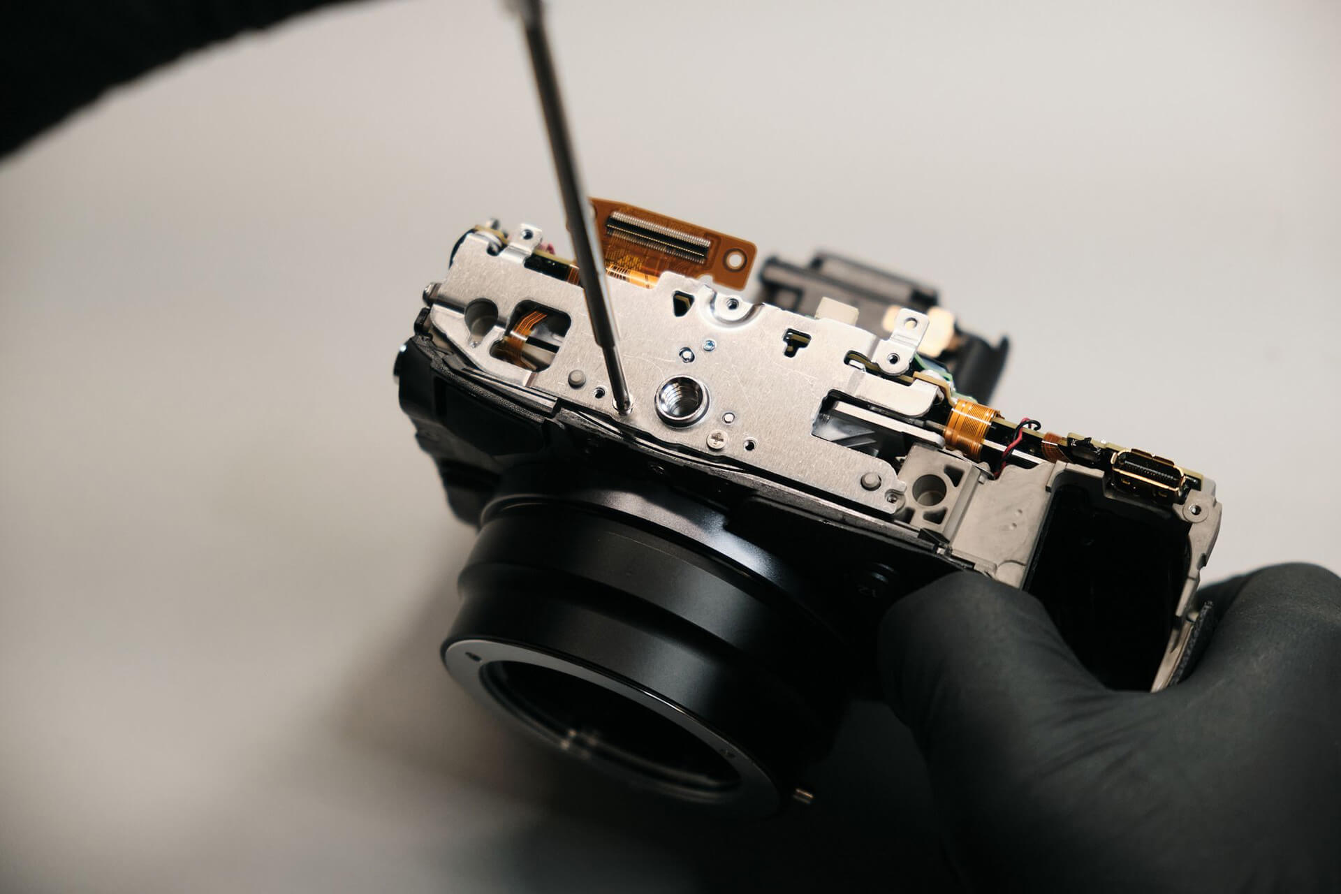
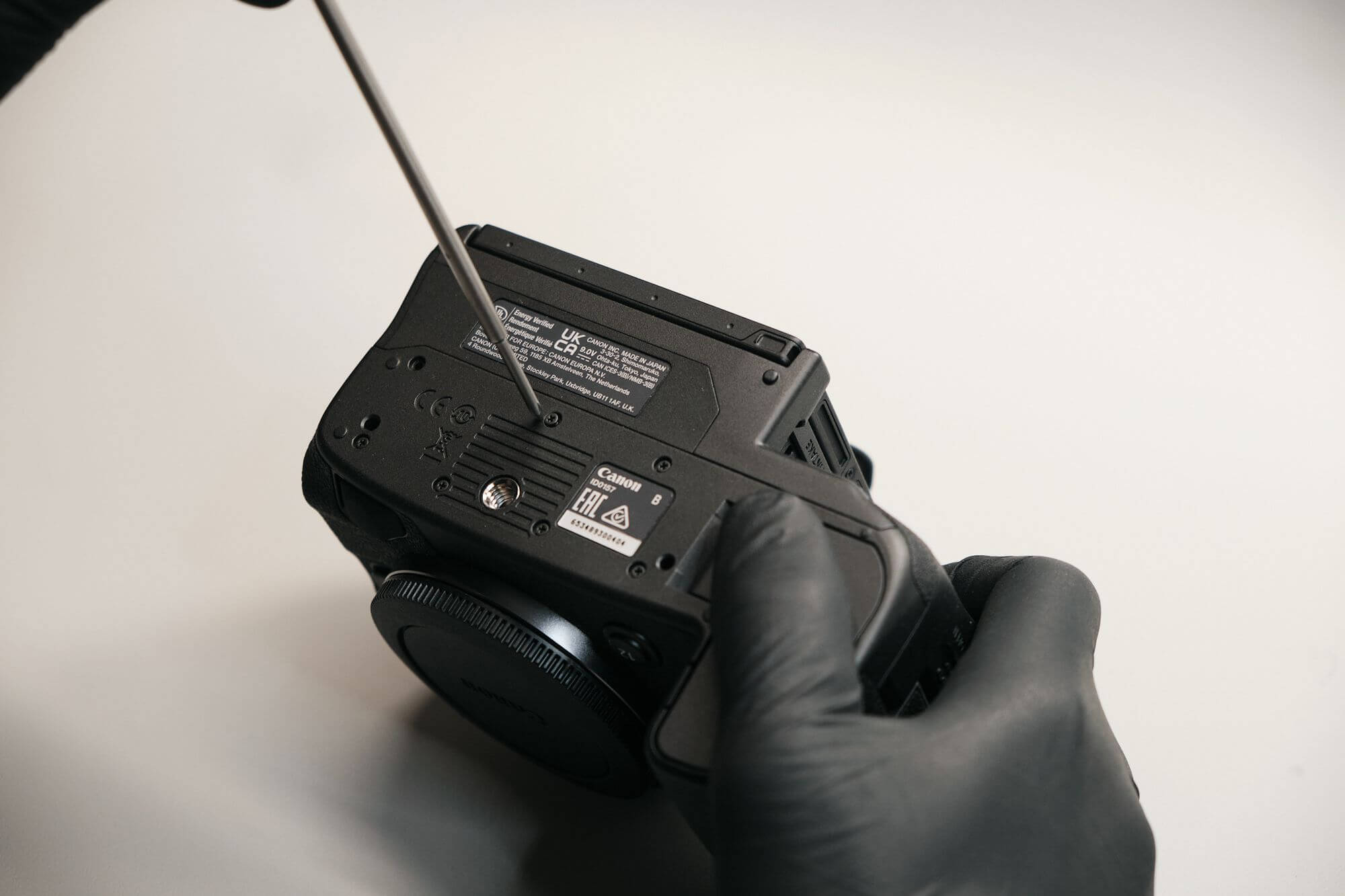
First, we removed the screws at the bottom of the camera. There are seven screws located underneath the camera, including a hidden screw under the battery door.
Removing Exterior Screws, Hidden Grip Screws, and Port Side Cover
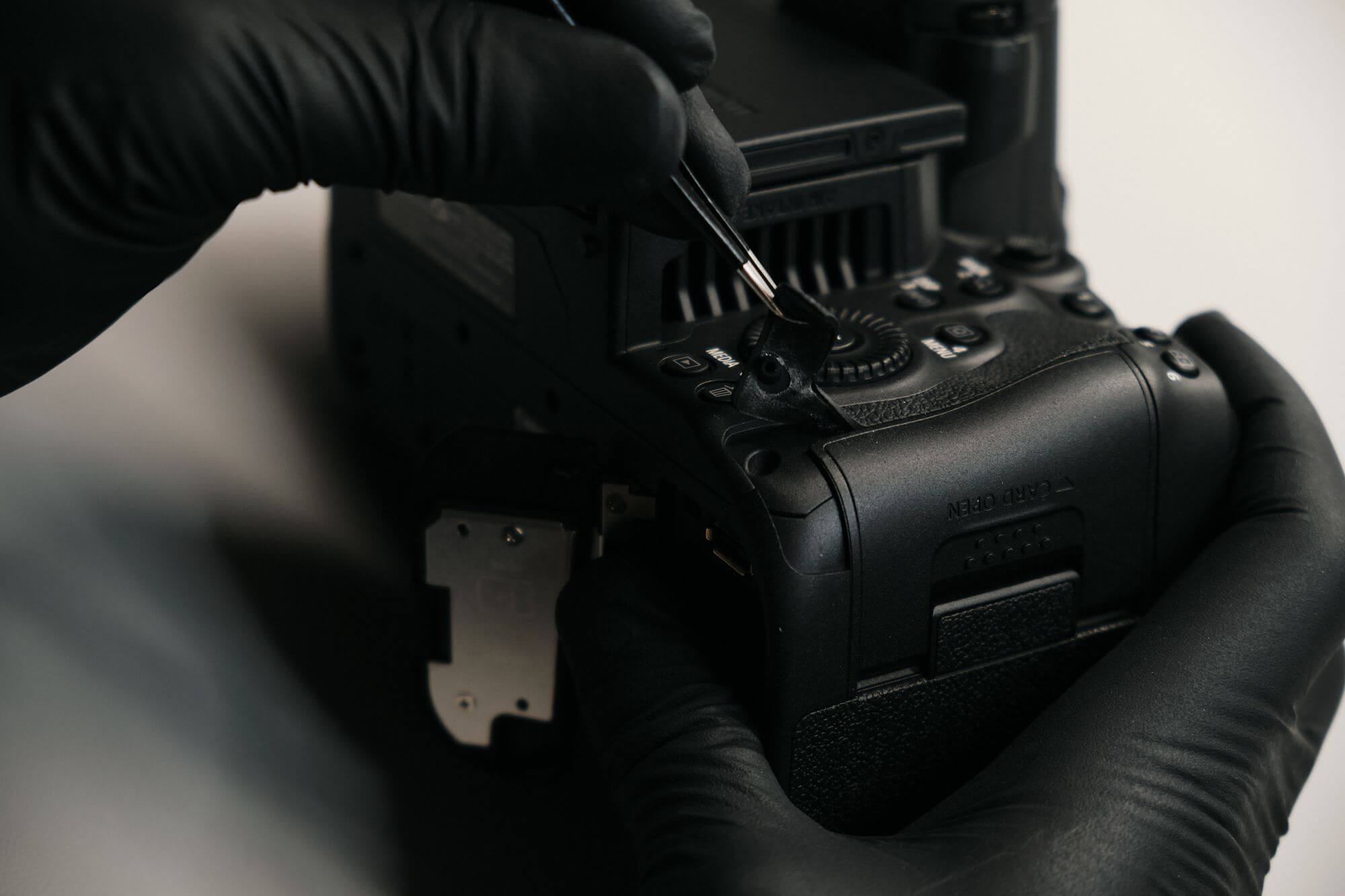
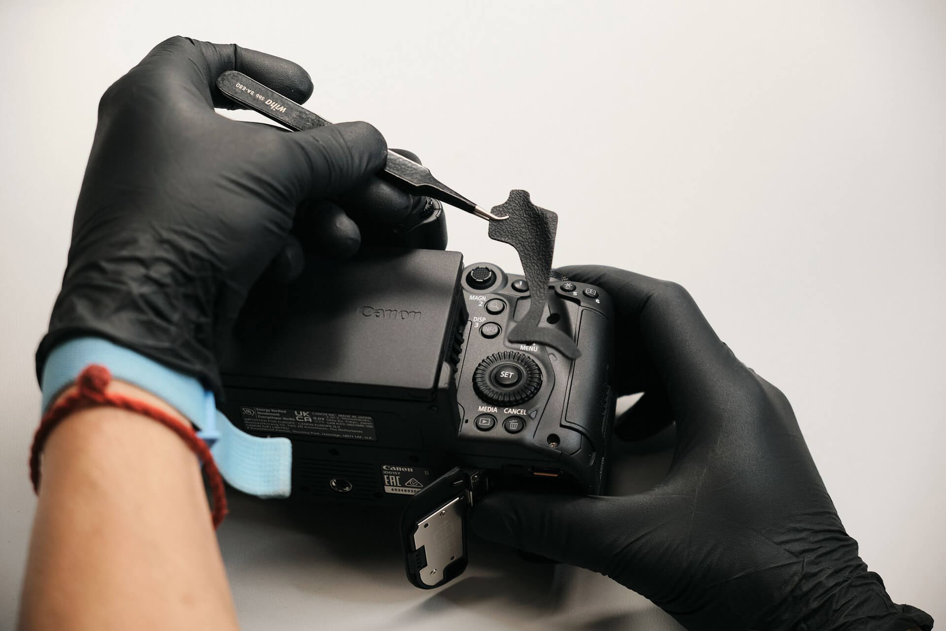
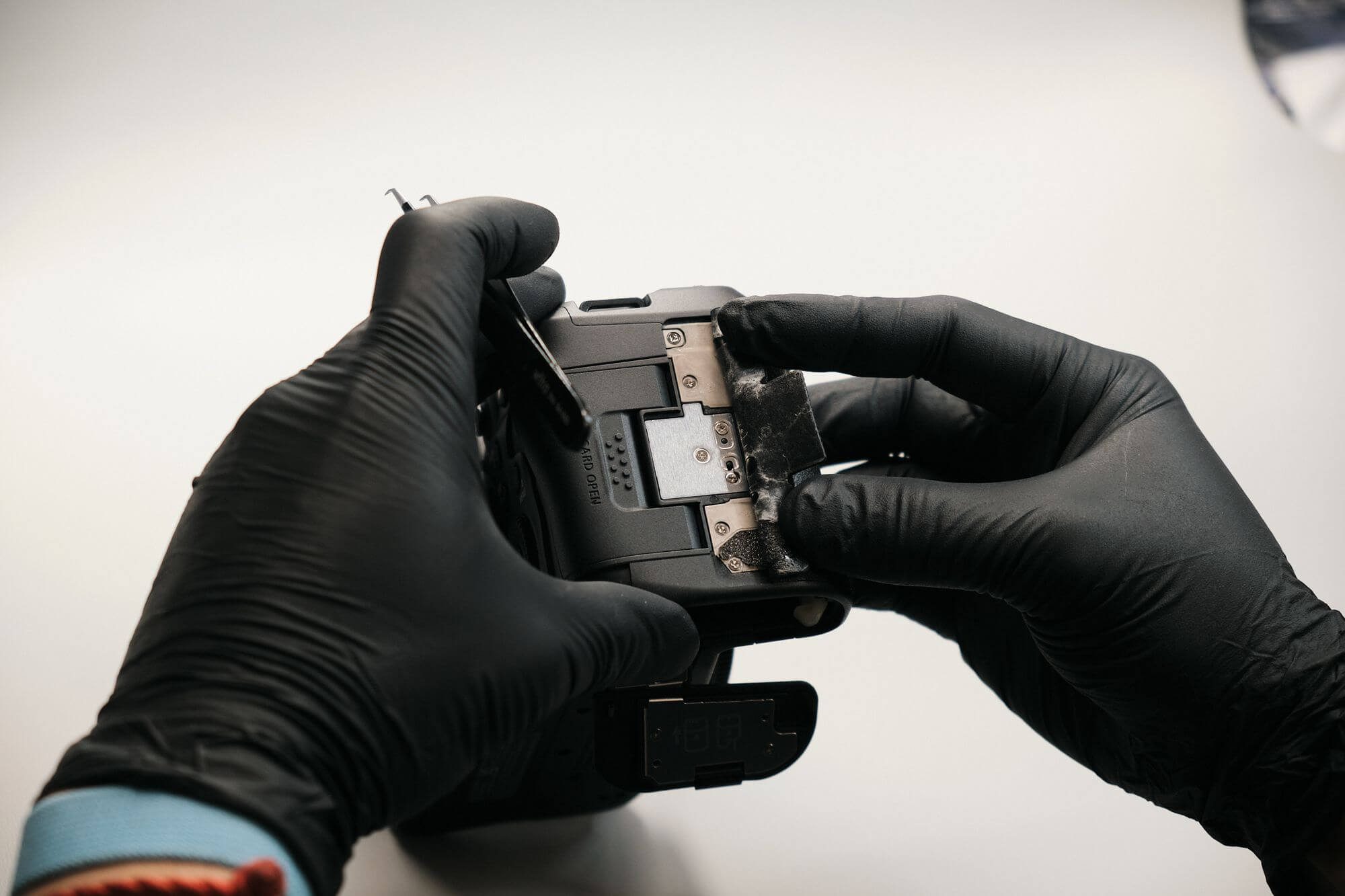
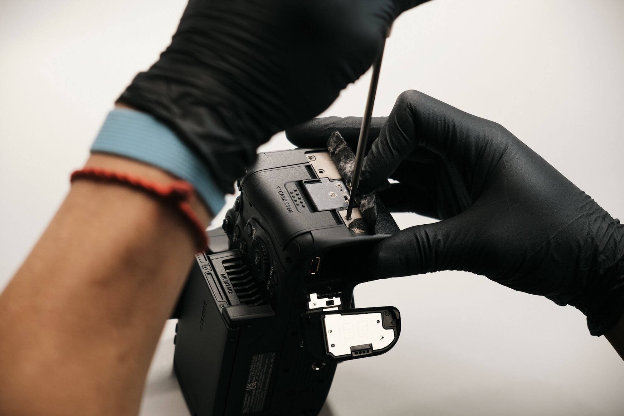
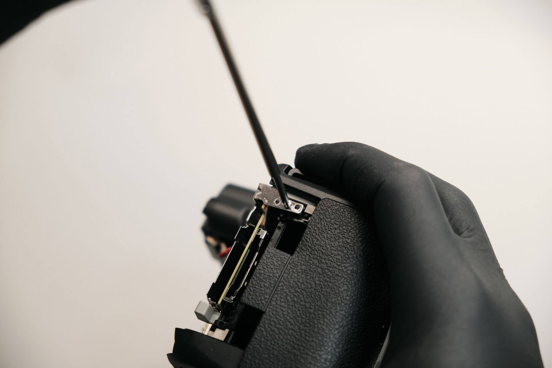
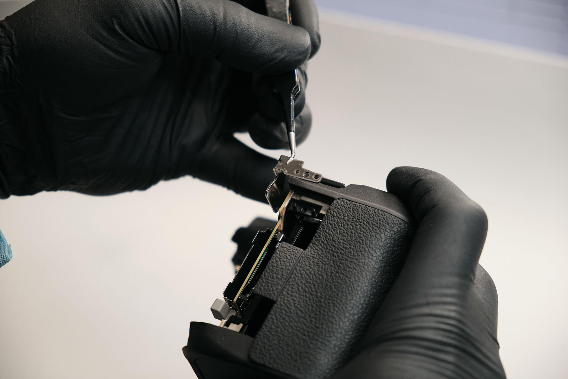
Many cameras have hidden screws under the leather covering. Often, fully disassembling a camera will require its removal. In this case, lifting and peeling the rear panel rubber grip exposed two silver screws.
On the other end of the Canon R5C, we found four silver screws on the right side below the leather cover grip.
Five screws hold the top panel. The first two screws to remove were located near the strap mounts.
The next one is right under the shutter button, and the last two are inside the body. We will see them later on during the EVF removal.
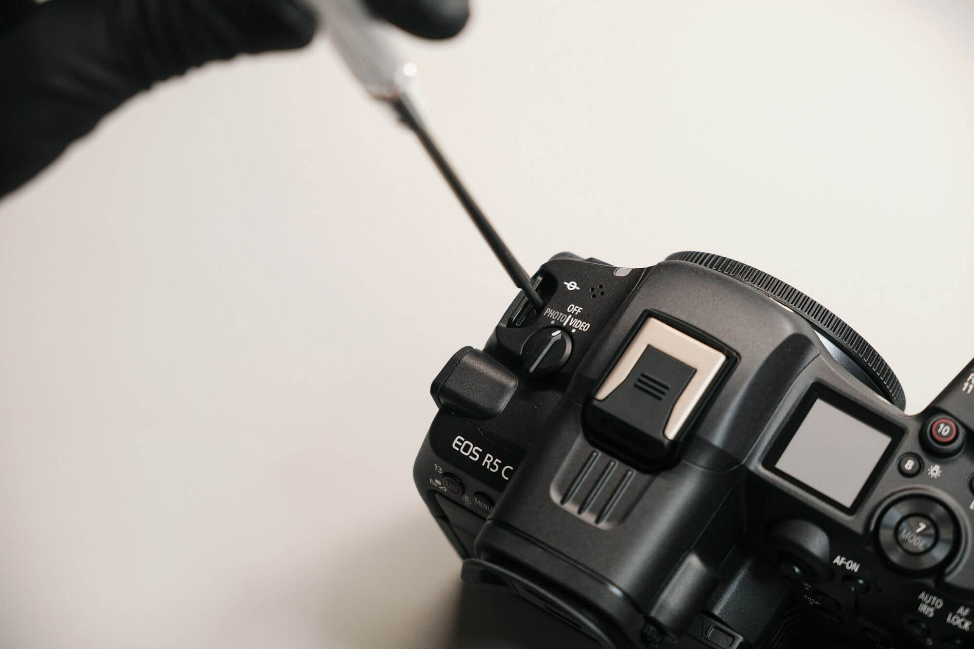
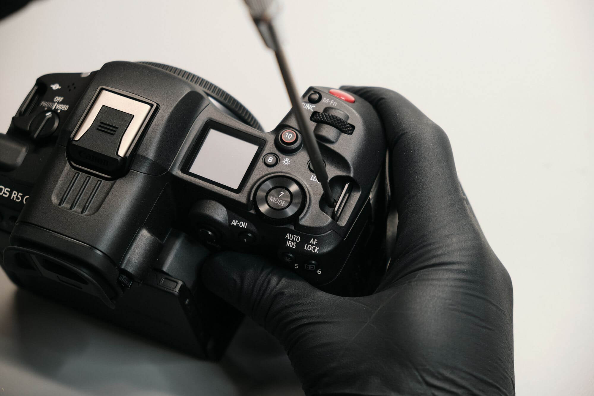
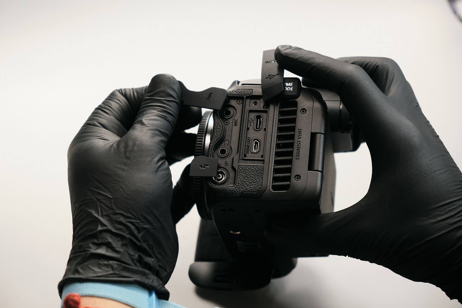
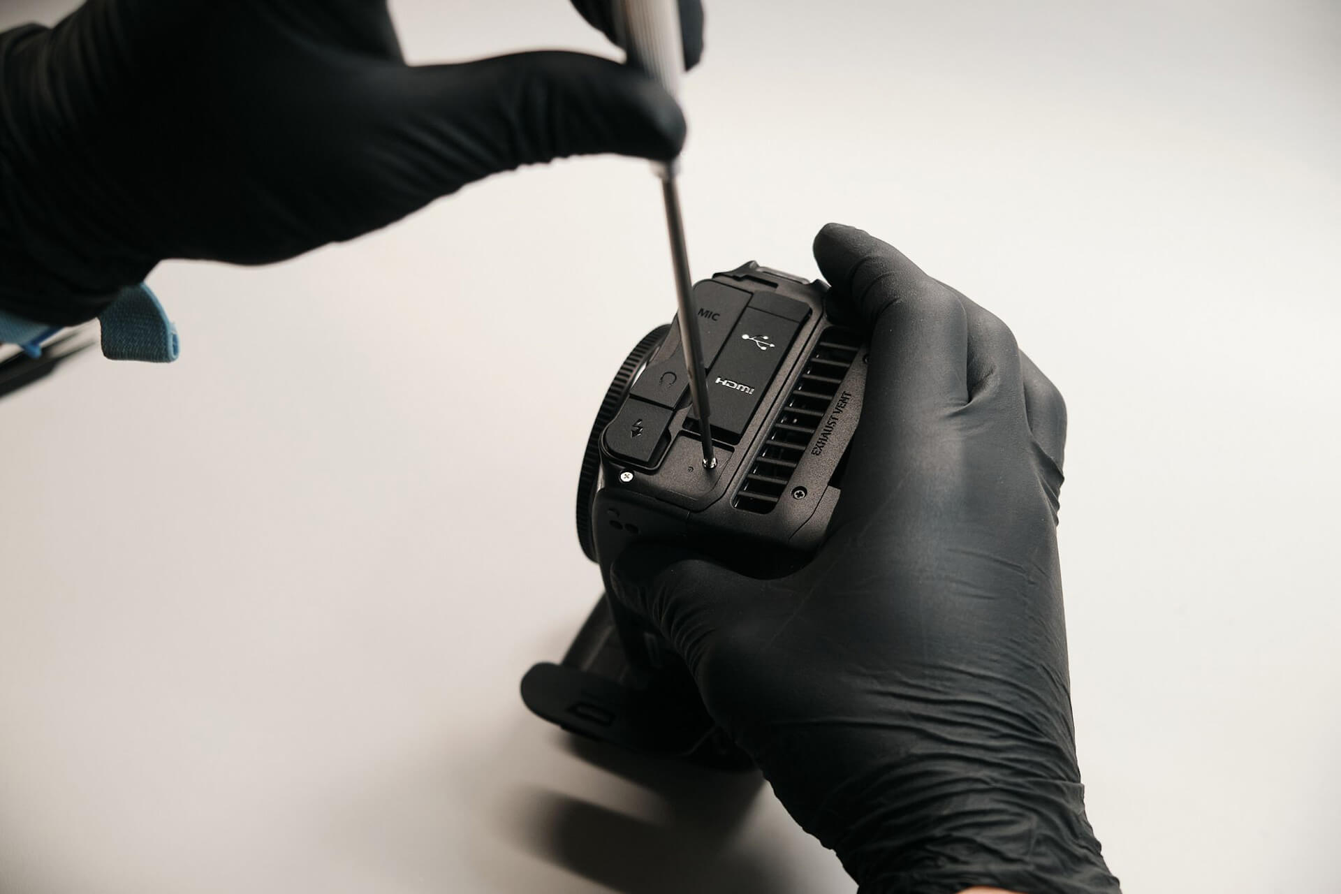
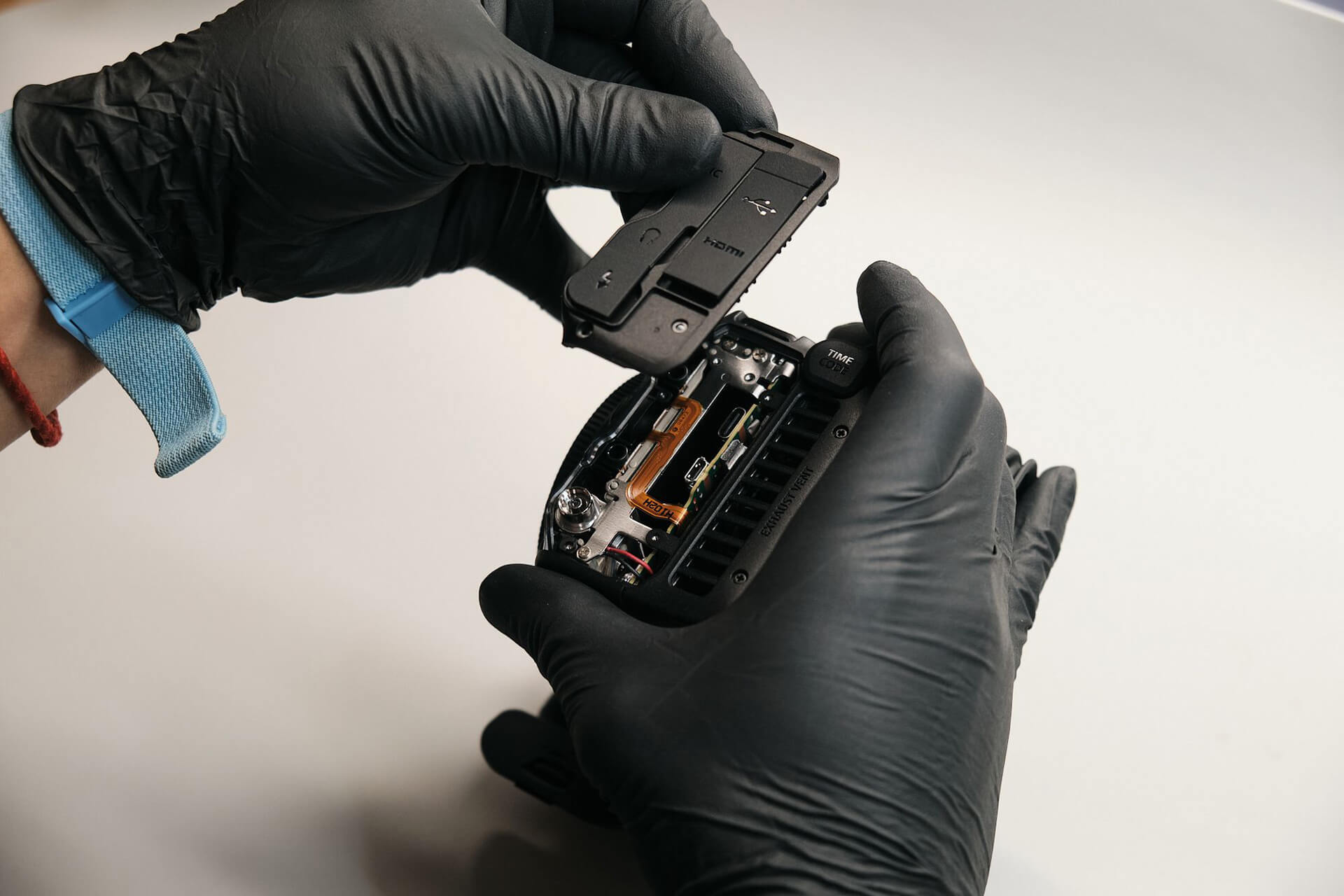
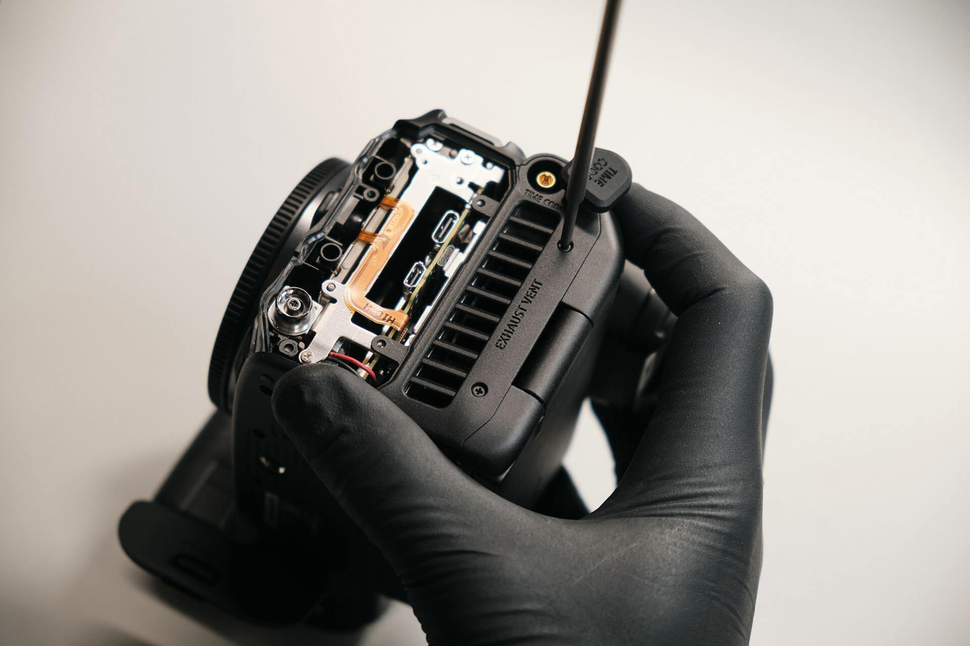
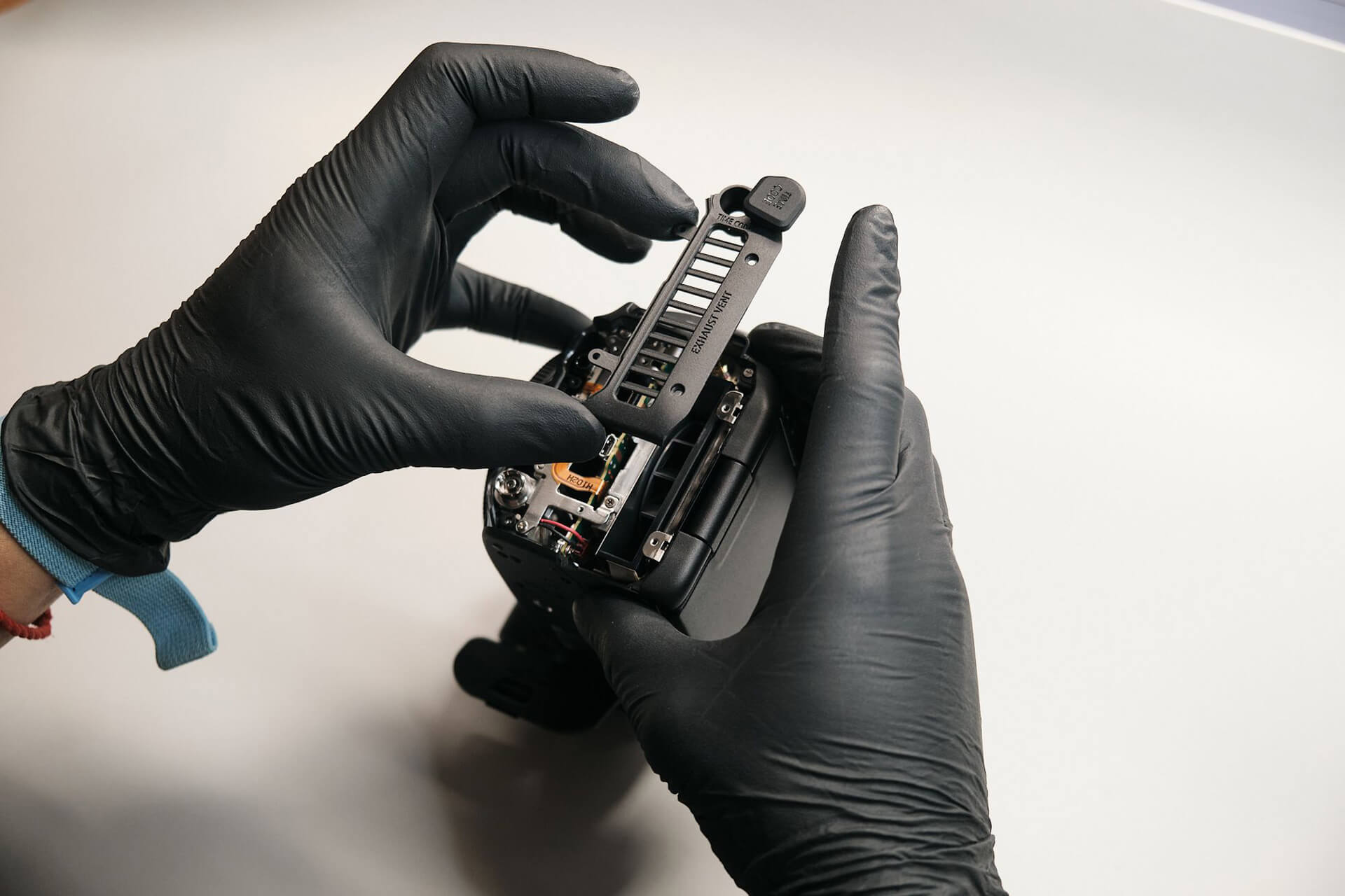
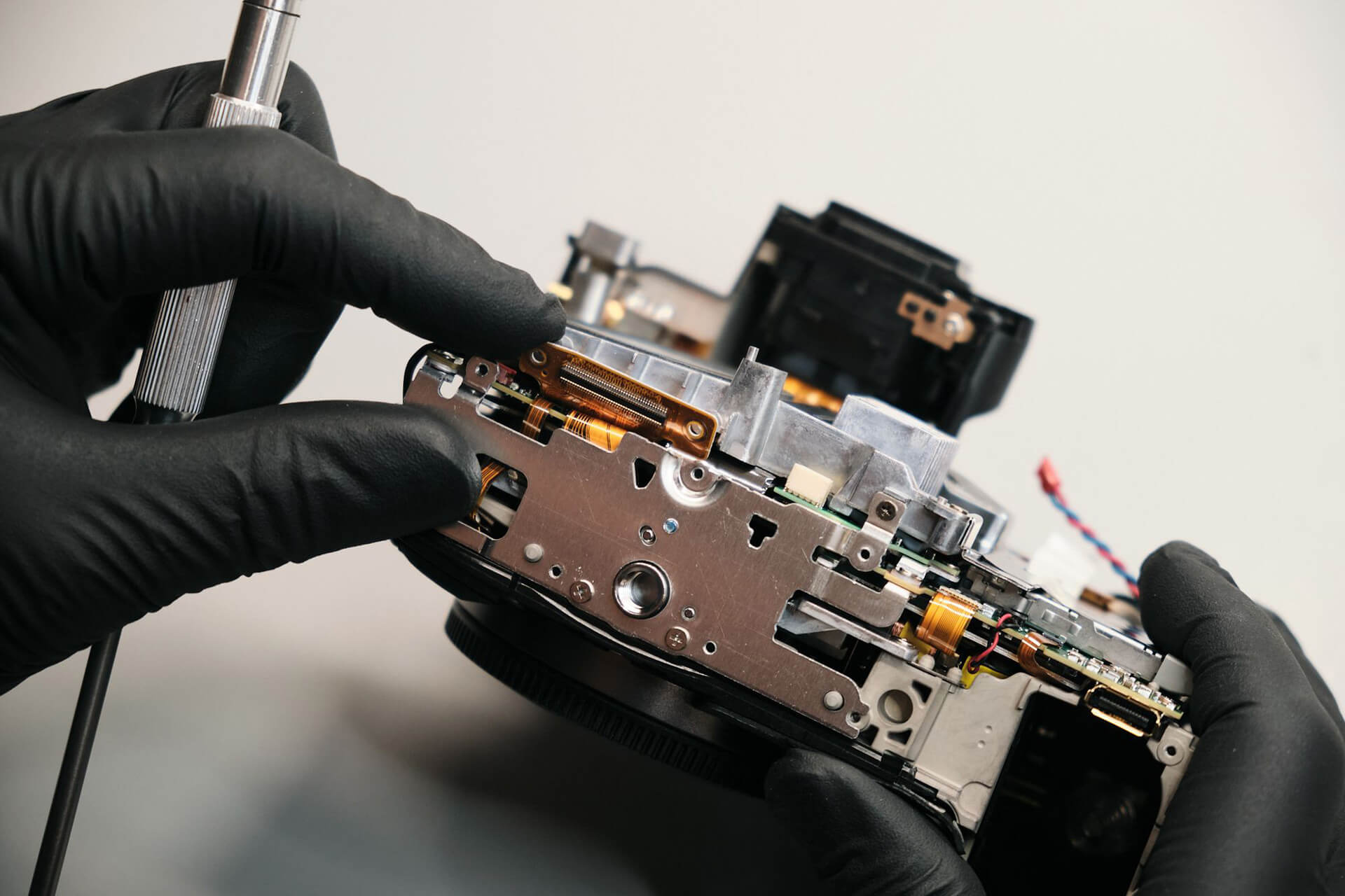
Popping off the dust caps on the port side, we found three screws. The vent for heat dissipation is held with two screws.
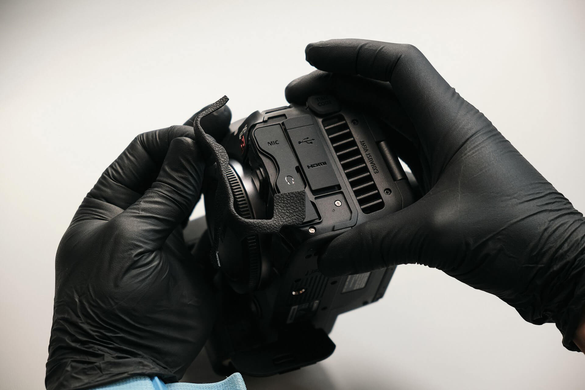
Peeling off the rubber grip on the port panel revealed two silver screws.
Removing the EVF Area and Rear Panel
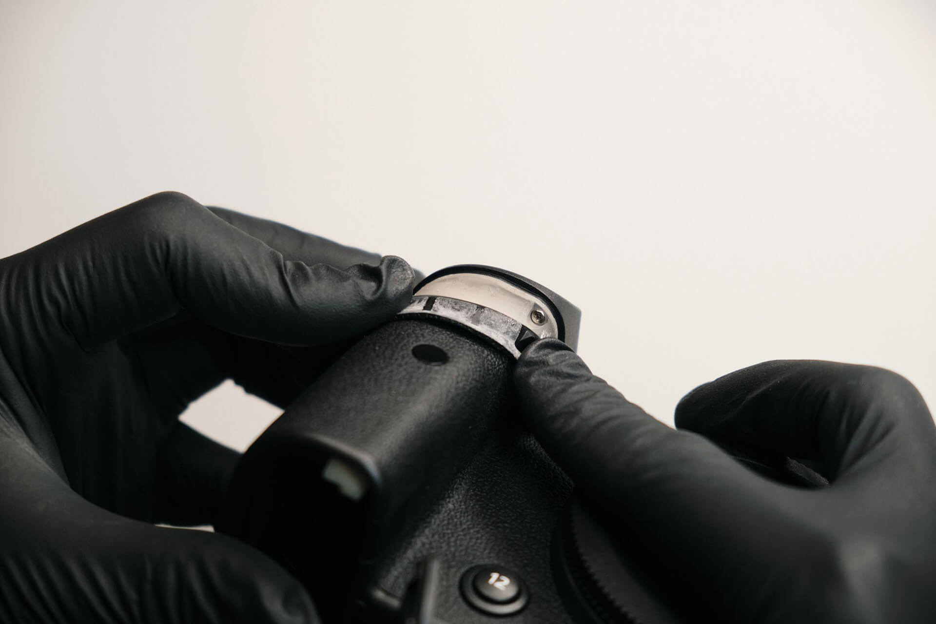
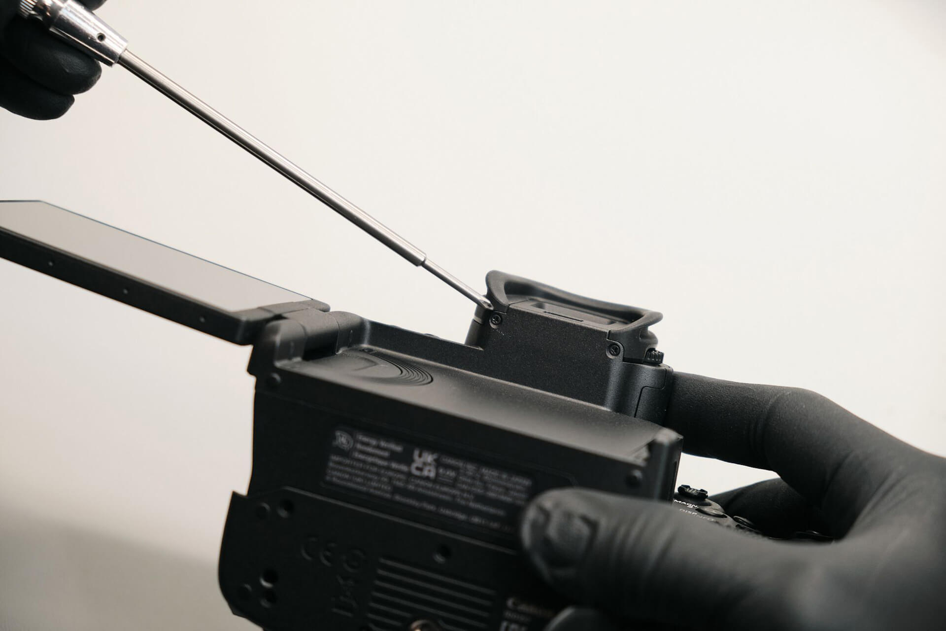
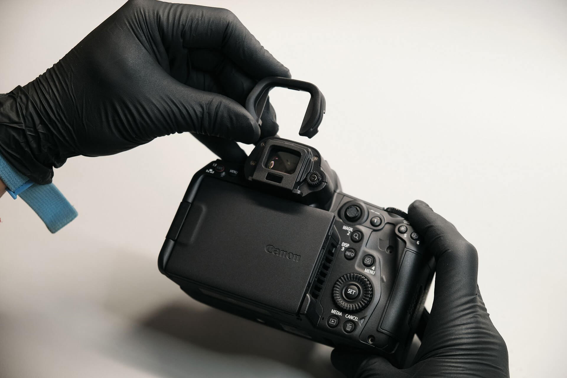
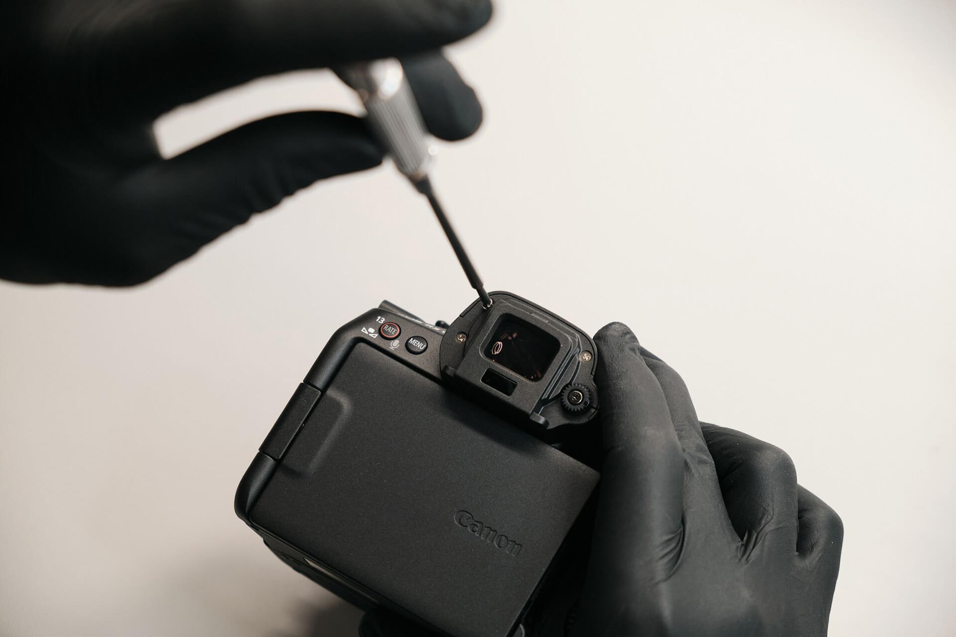
The eyecup was held down with two screws and came off easily.
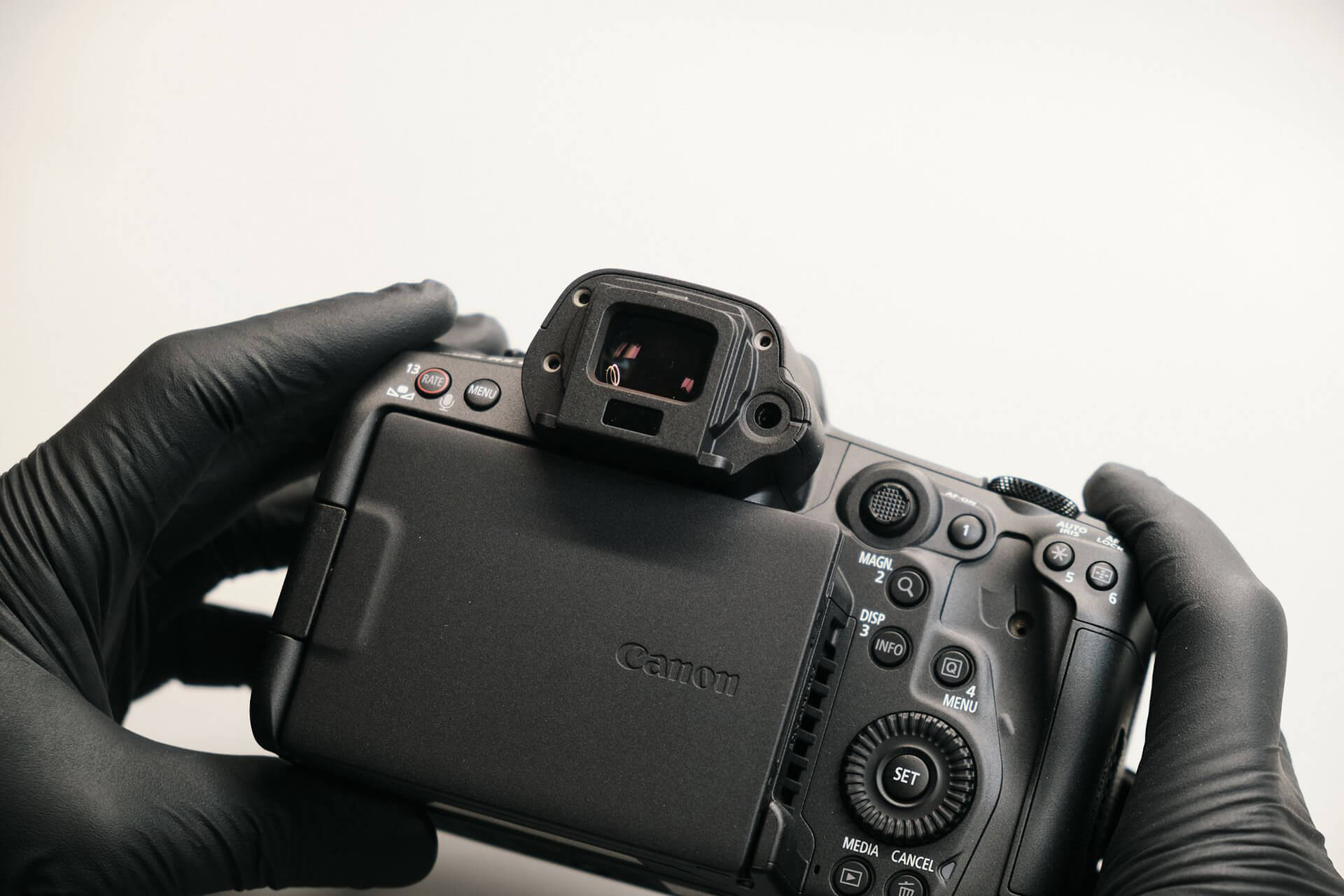
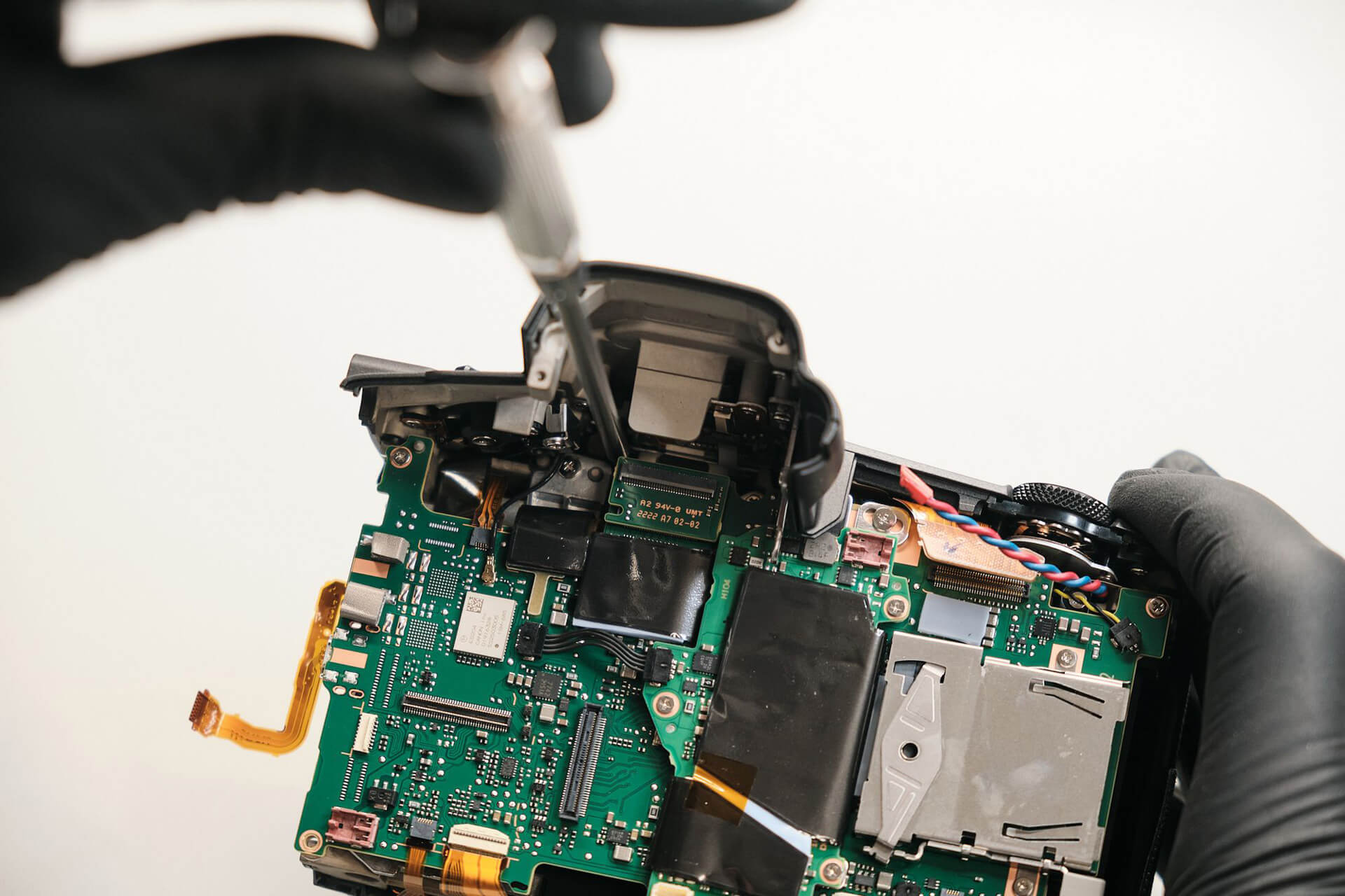
Removing the eyecup showed three silver screws that presumably hold down the EVF and a single screw that held down the diopter adjustment knob.
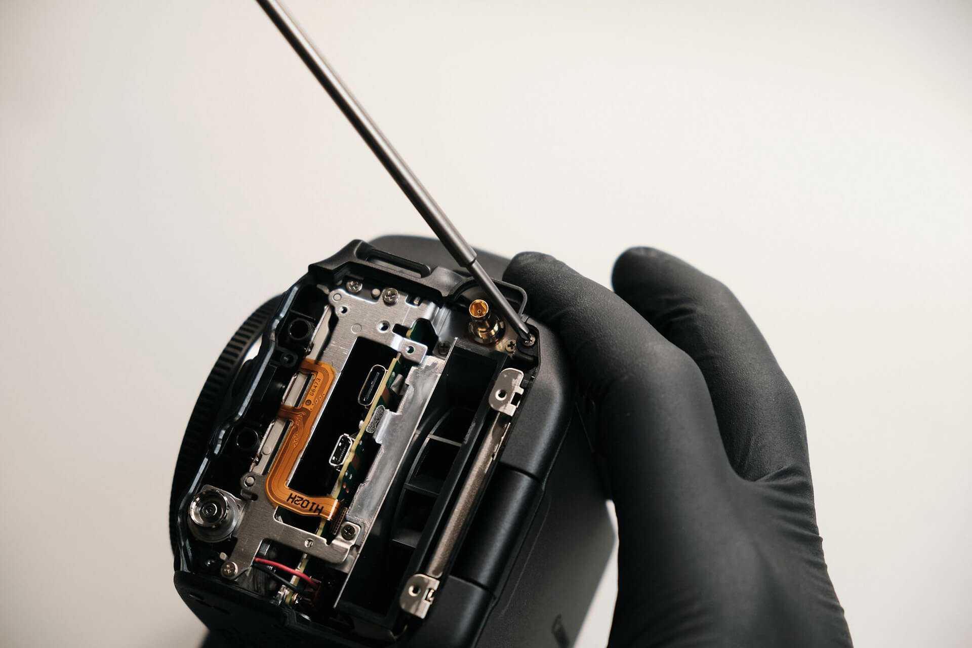
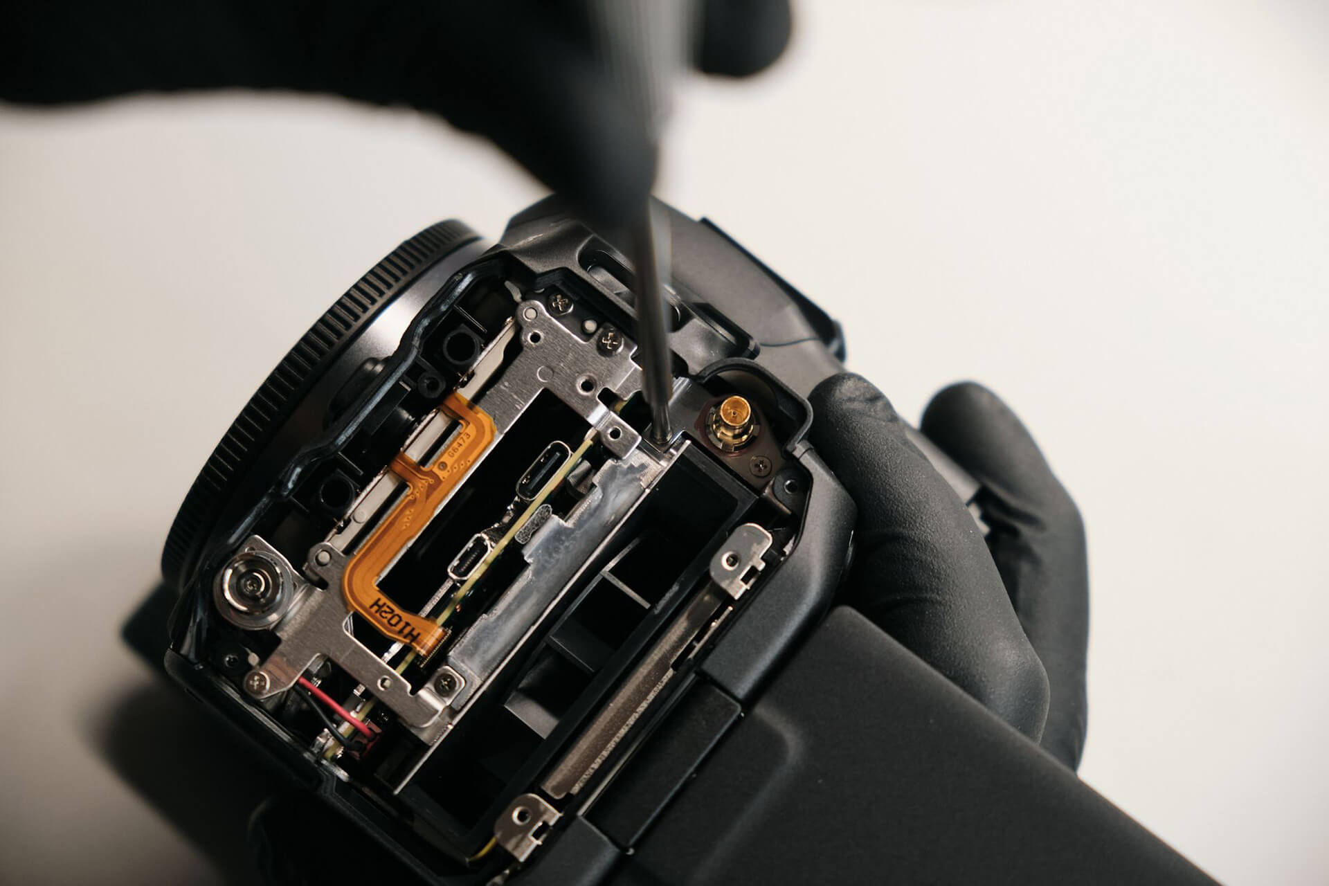
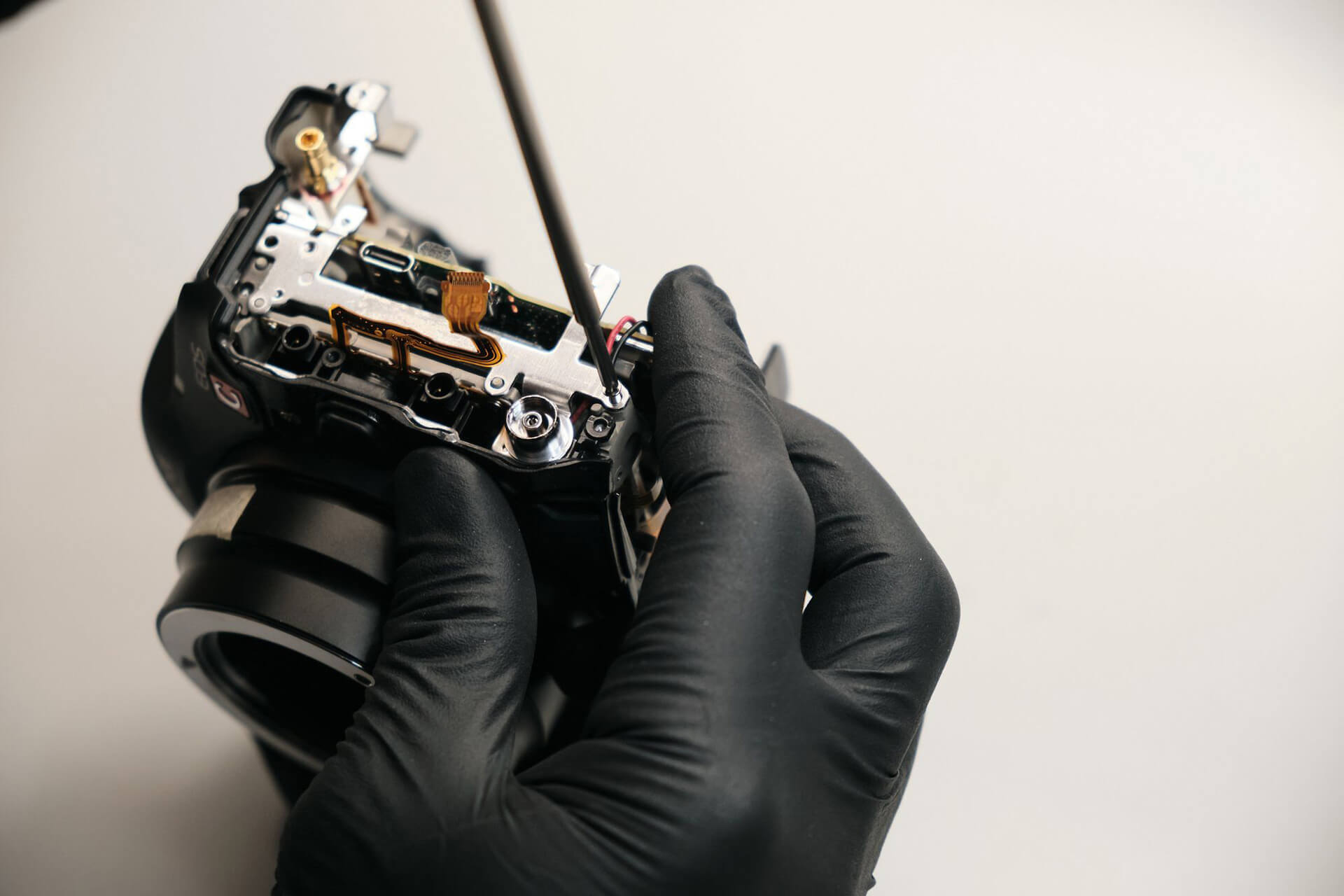
At some point during the teardown, we had difficulty figuring out why the rear panel wouldn’t come off. It turned out that there were two screws near the BNC time code port.
Disconnecting the Rear Panel and Accessing the Cooling System
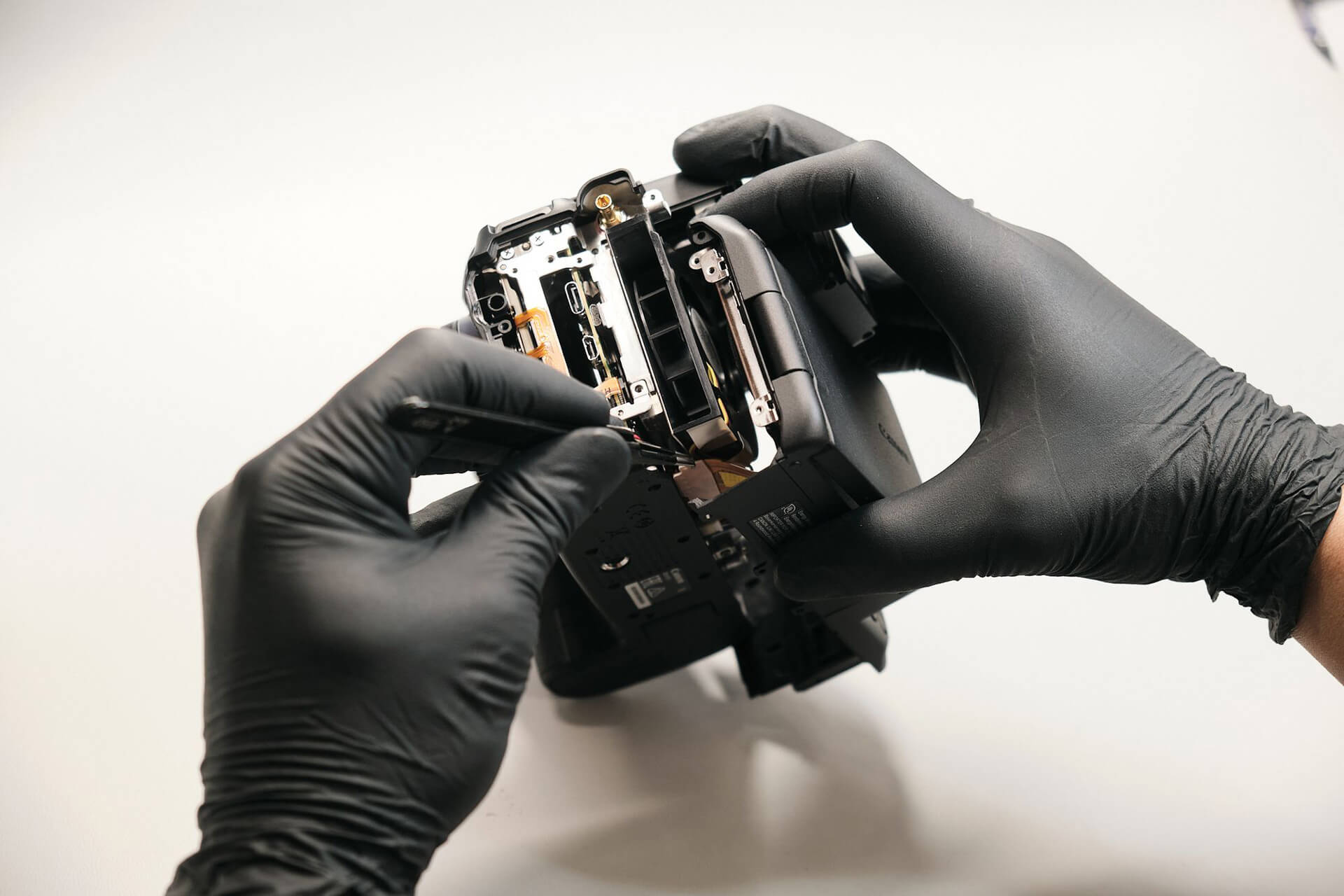
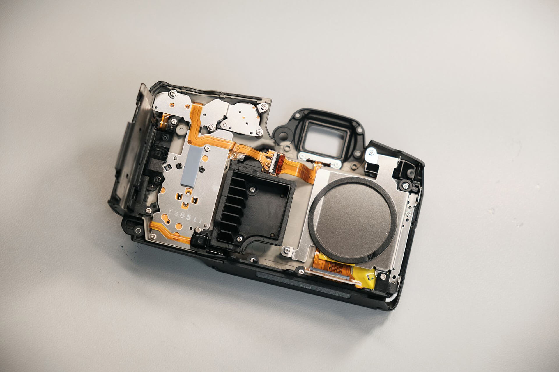
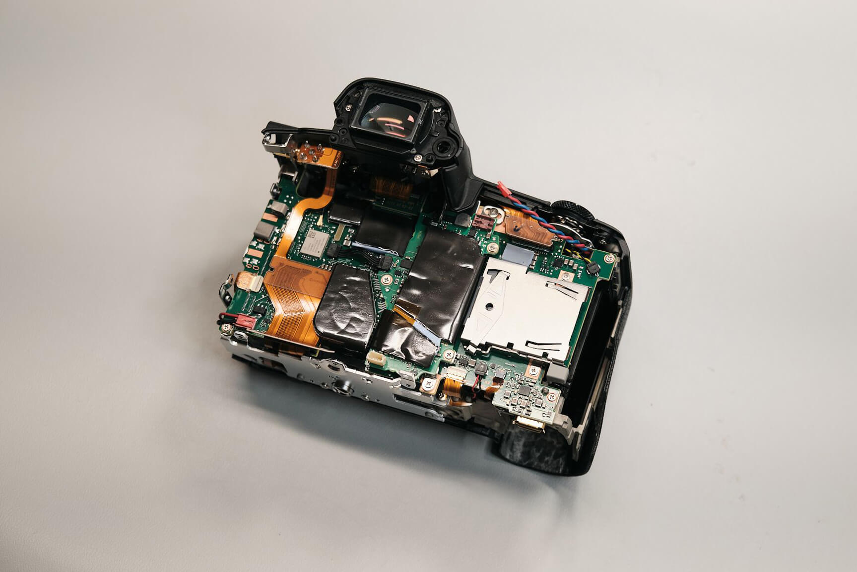
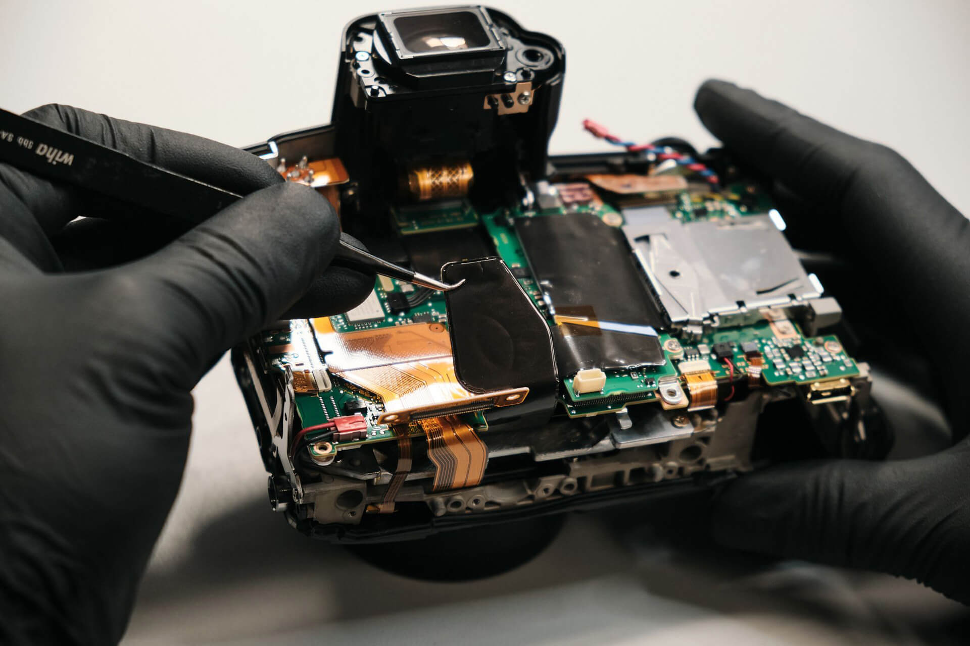
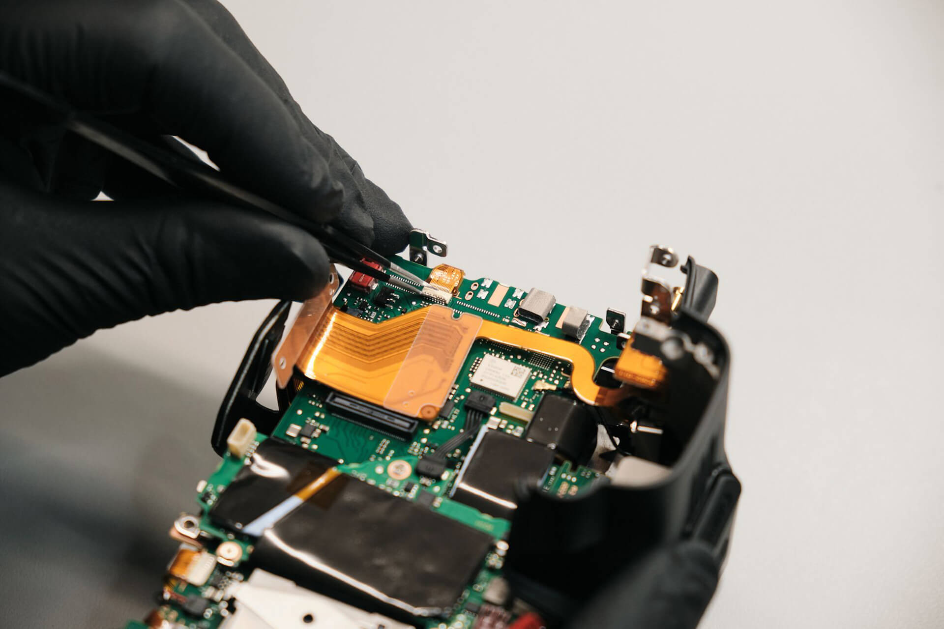
Before the rear panel could be removed, a large ribbon cable needed to be disconnected. We carefully lifted the rear panel to unfasten the ribbon. This ribbon connects to all buttons and the LCD monitor, so it was important to keep it intact.
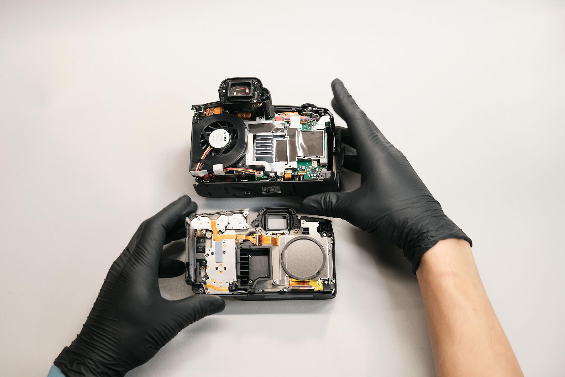
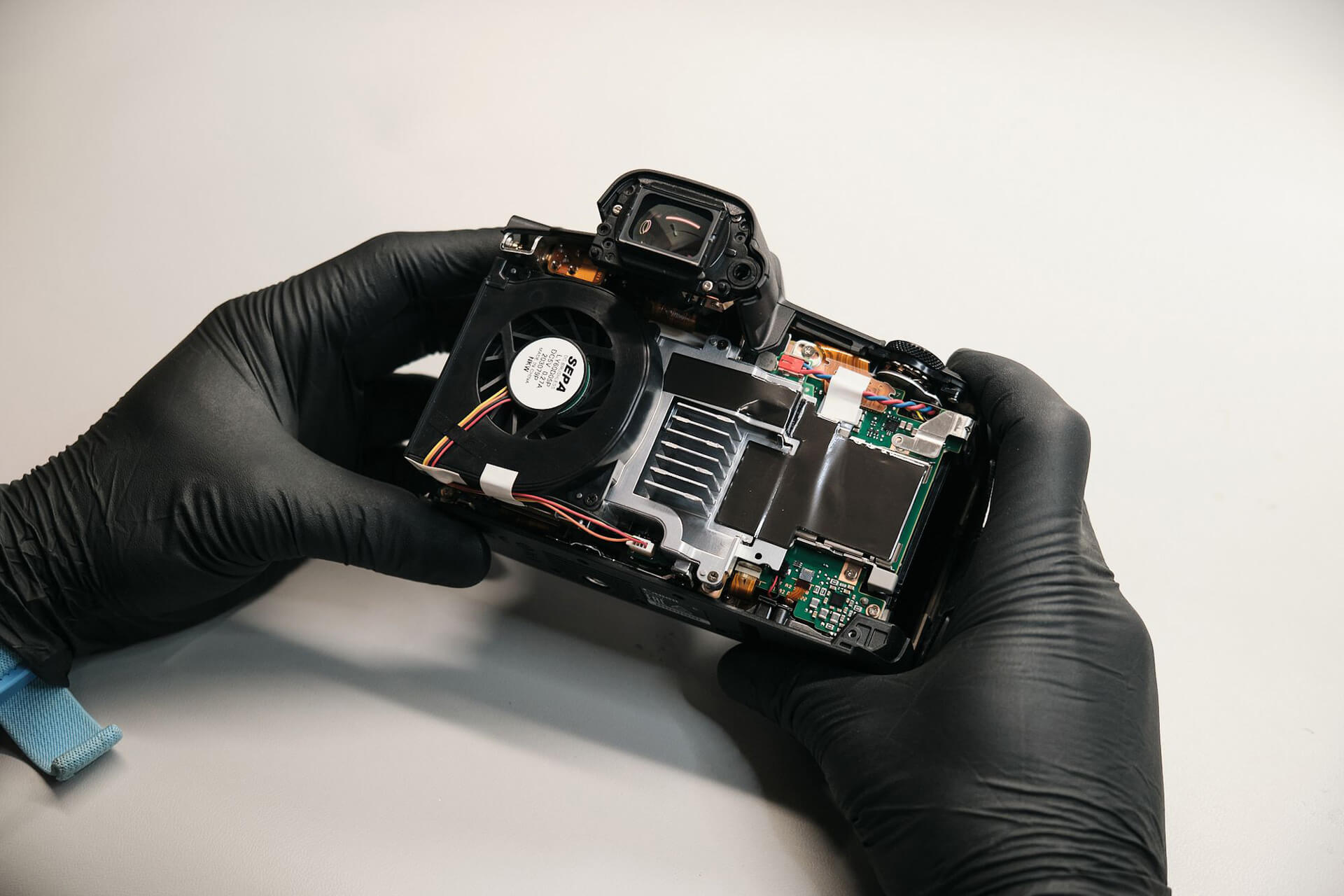
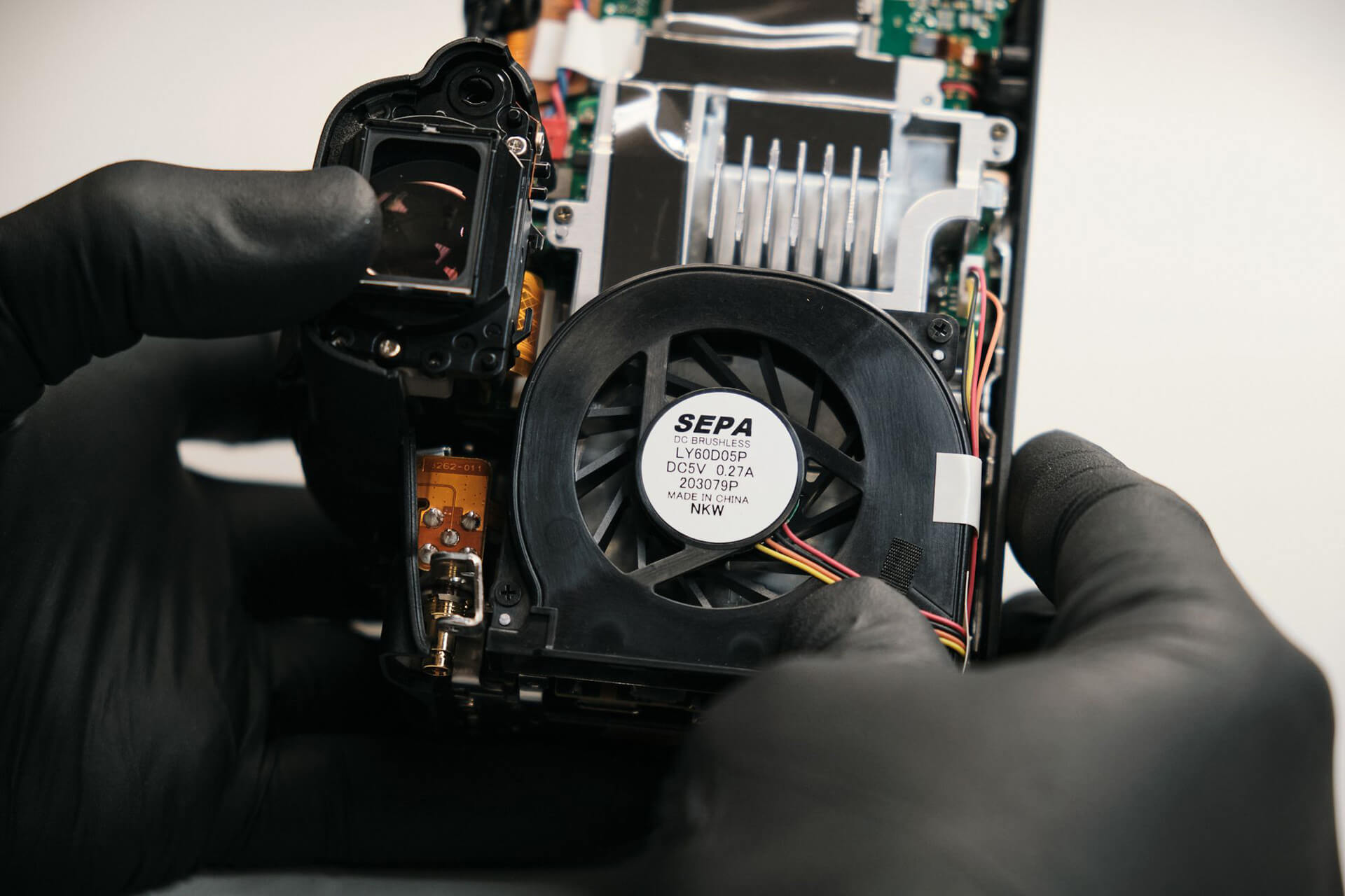
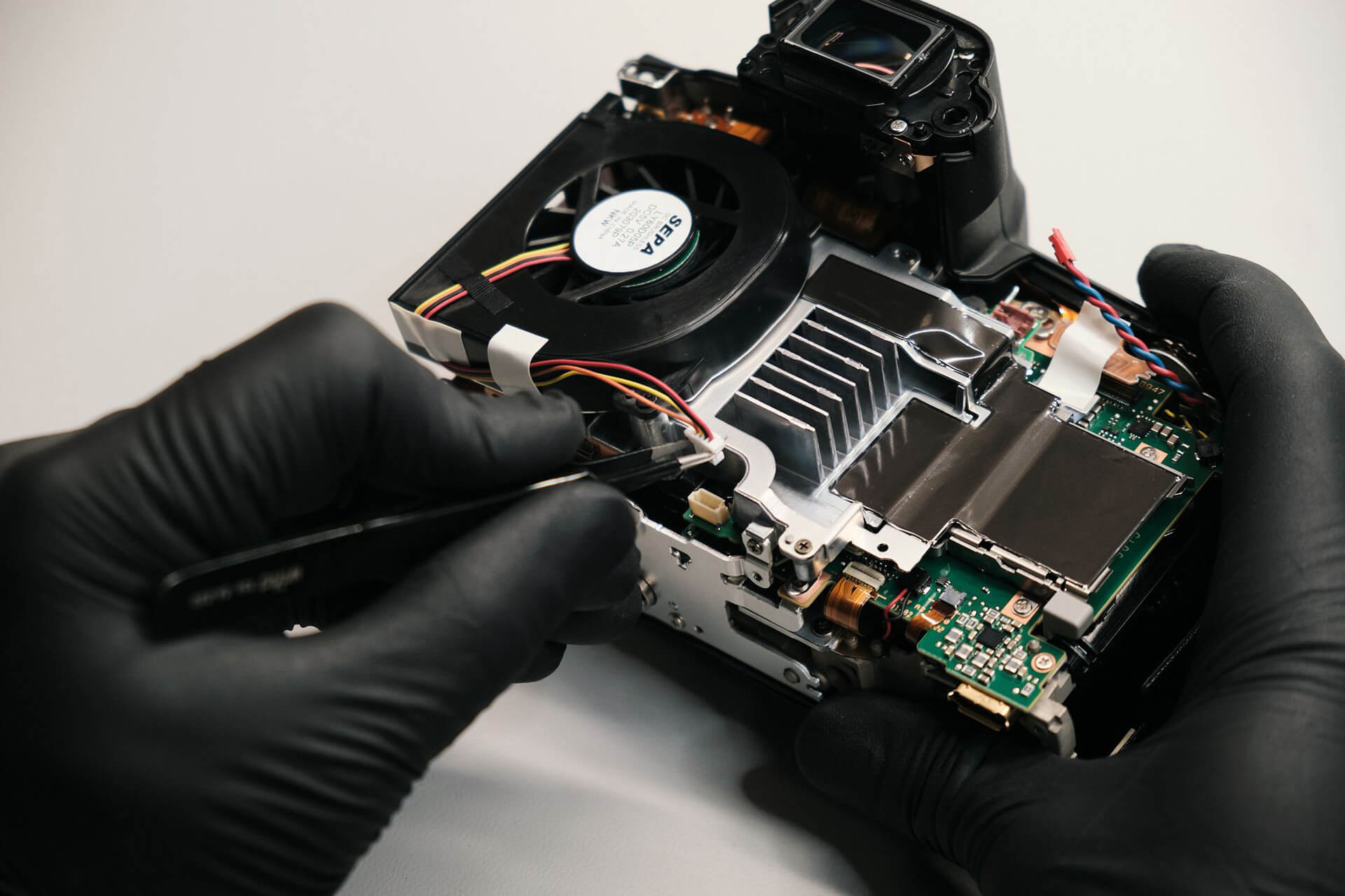
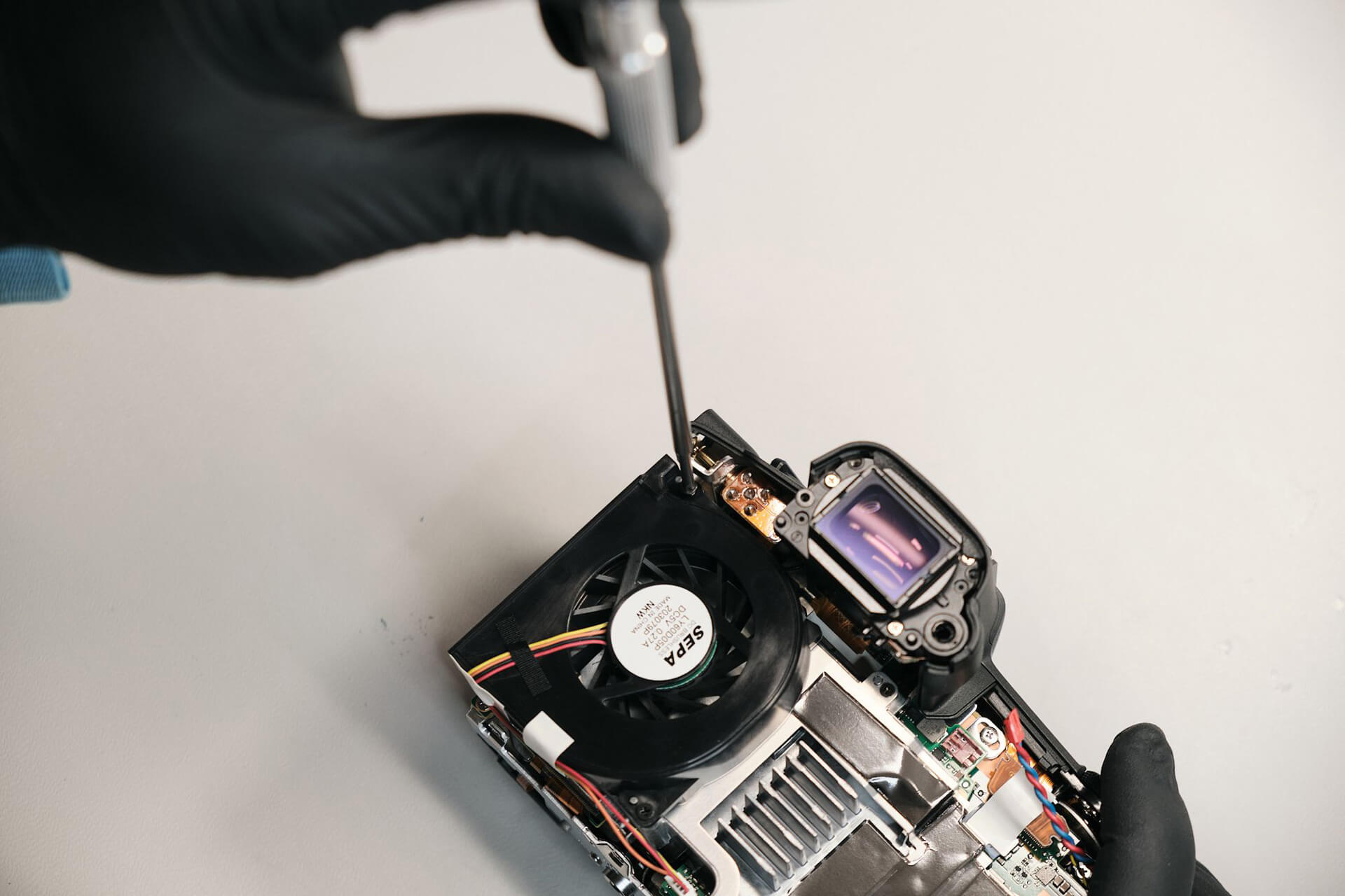
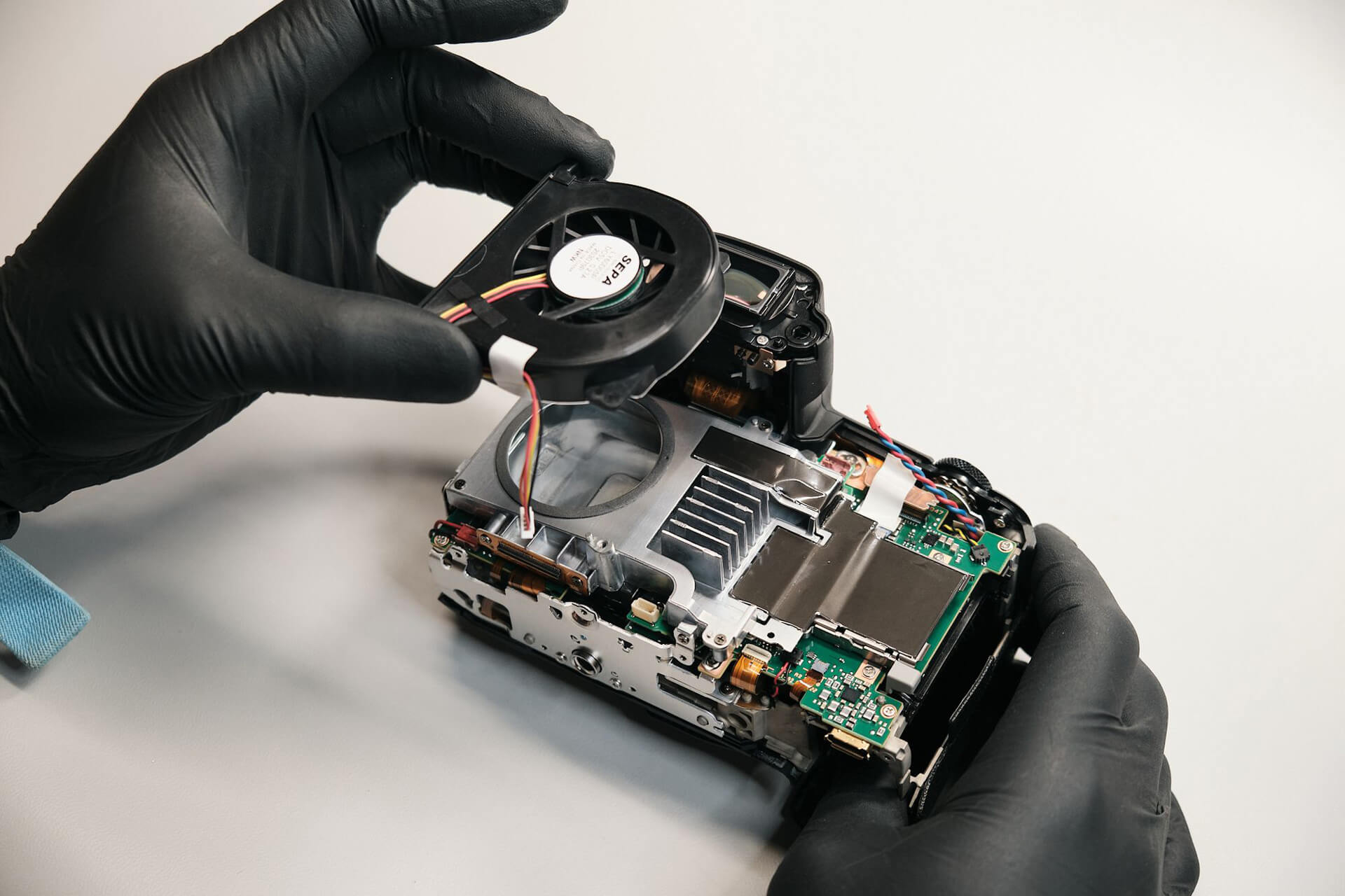
Check this out! SEPA is the manufacturer of the cooling fan for the R5C.
Removing Internal Brackets, Cooling Fan, and Heatsink
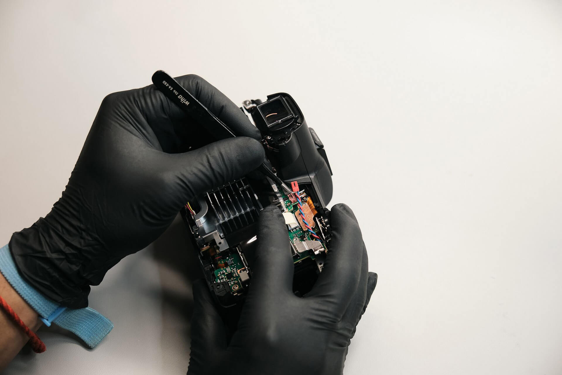
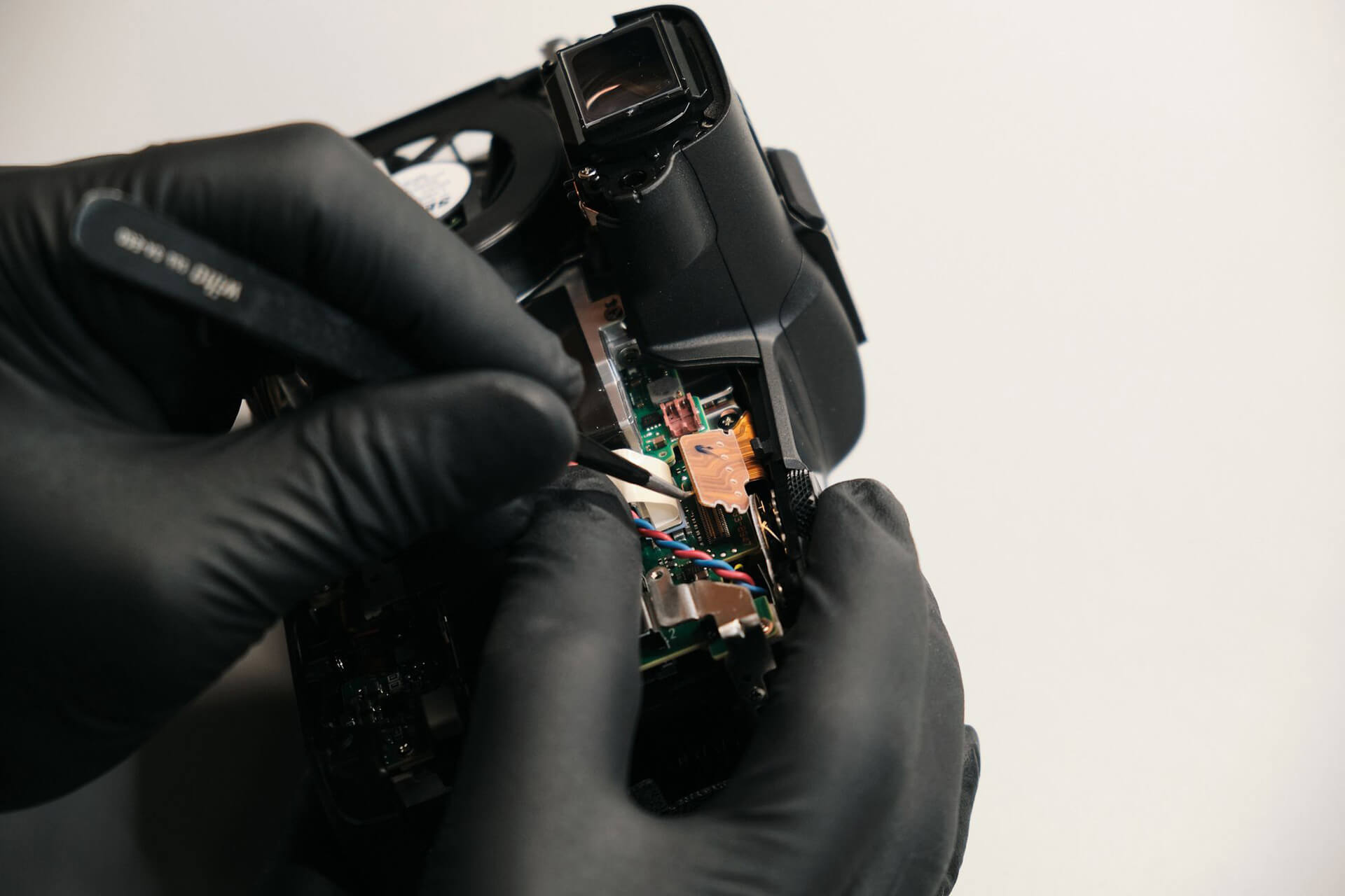
With new-found access to the internals, we were able to remove the motherboard power cable and ribbon for the top LCD screen, as well as remove the bracket for the rear panel.
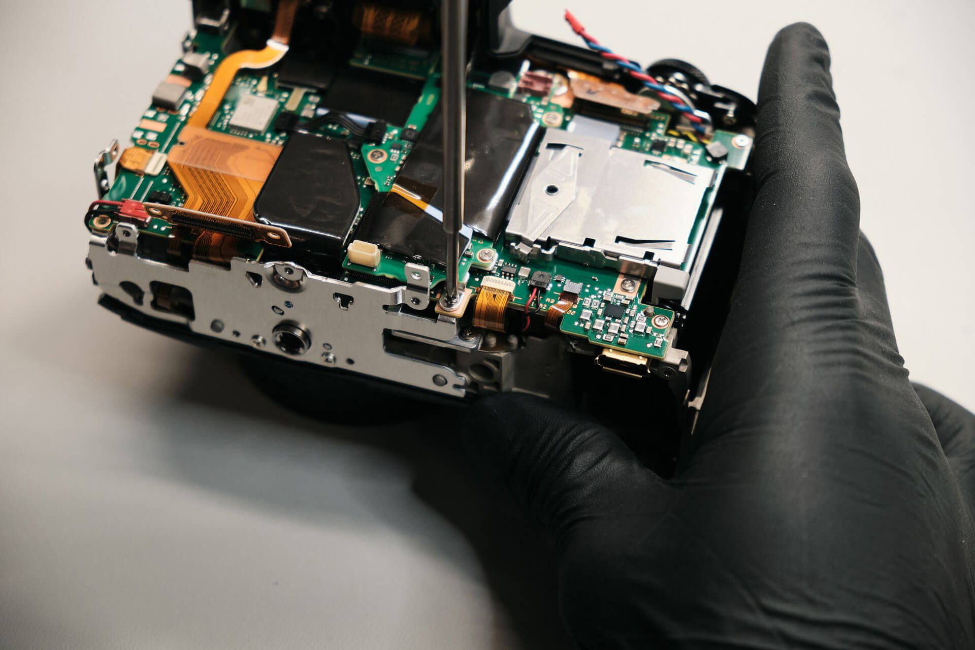
Similar to what we’ve found with the Canon R5, we needed to remove the bottom cover to prevent damage to the interlocking switch on the circuit board. There’s another screw below the leather grip on the camera’s handle side.
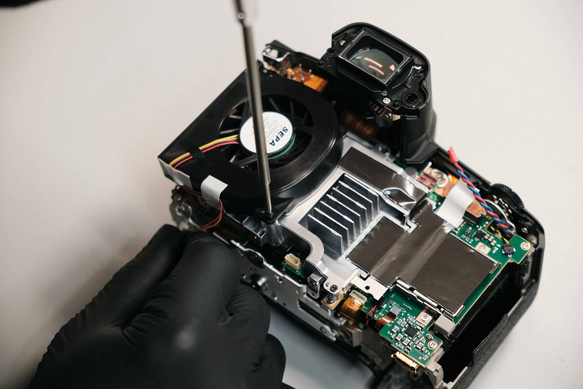
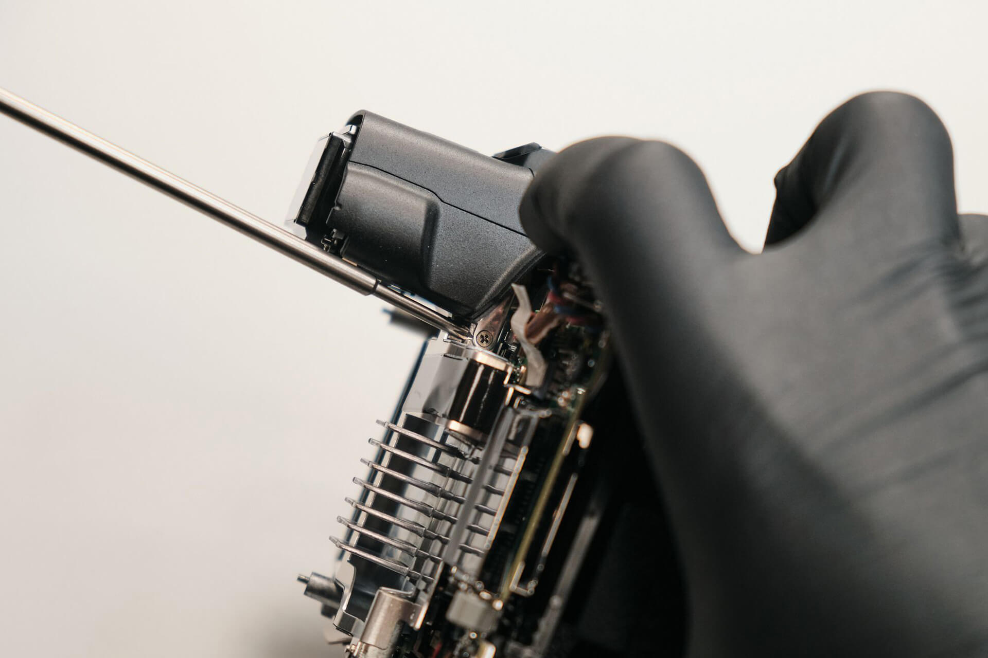
We removed the cooling fan wire by disconnecting the PCB and two screws.
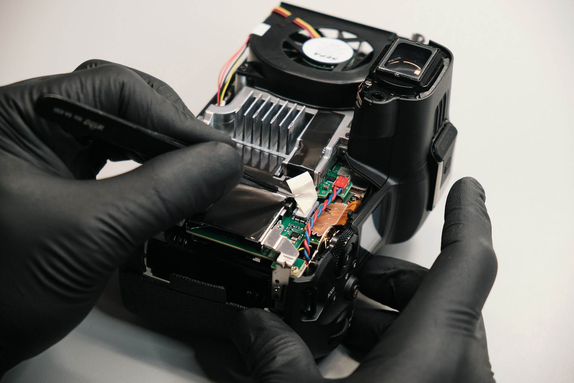
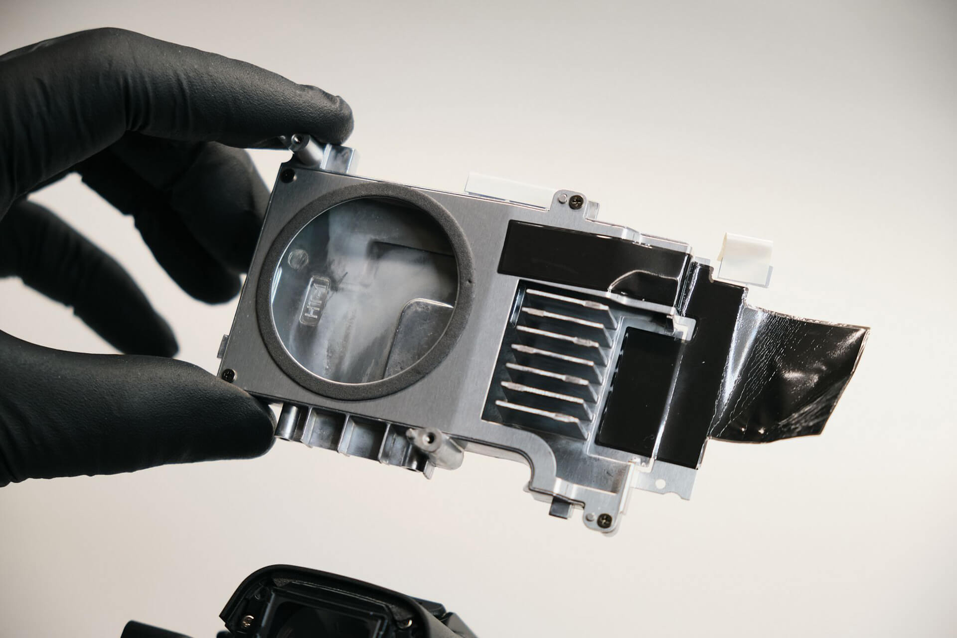
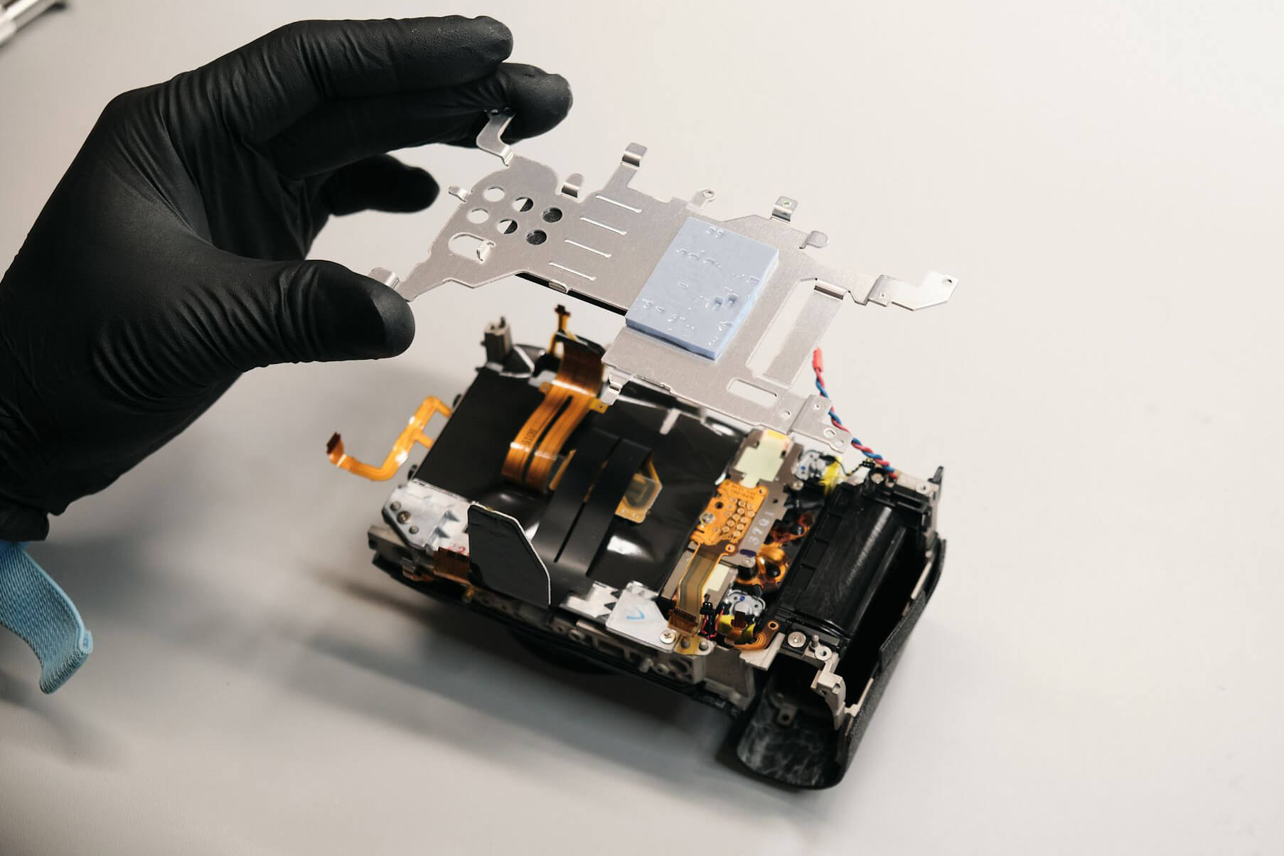
The next thing to get done before we could continue was removing the large heat sink. First, we removed two screws holding the ribbon.
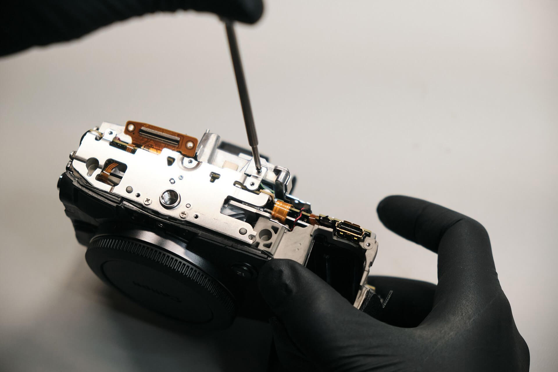
The following two screws that needed to be unfastened were at the bottom and top panel brackets.
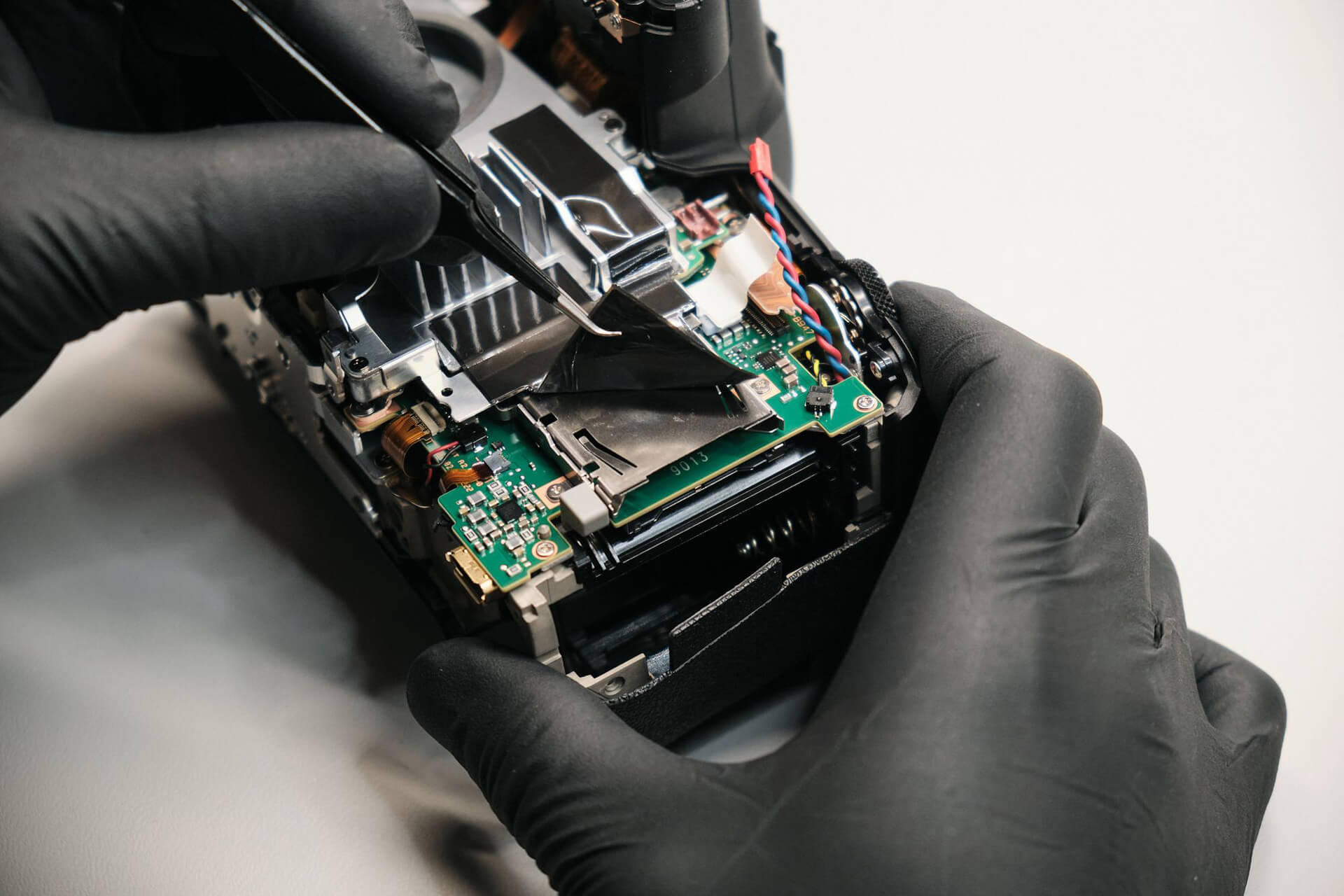
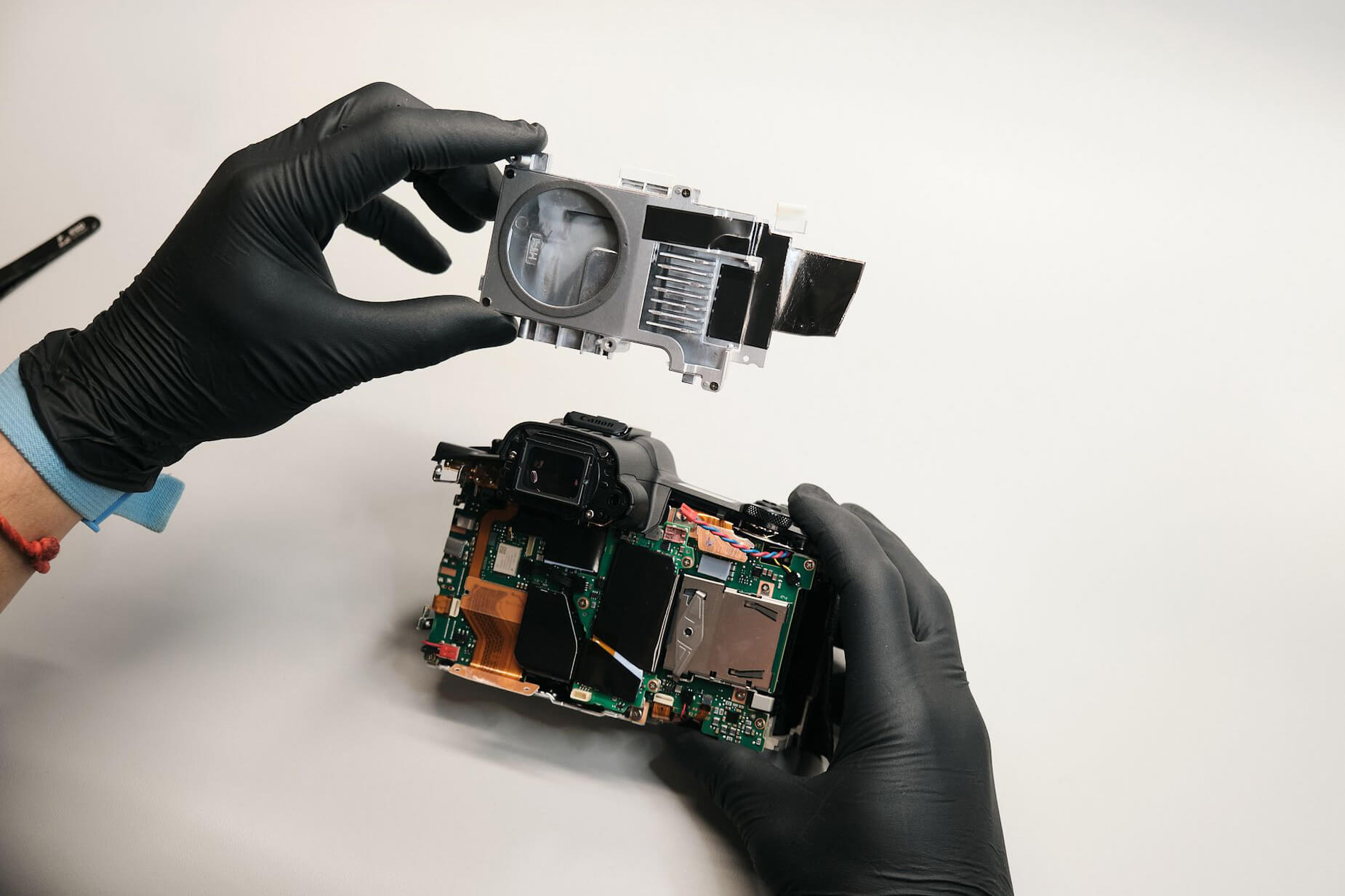
We needed to peel off the heat transfer tape on the CF express slot to remove the heat sink. Canon used several heat pads and transfer tape on this model.
Removing the Top Panel and Circuit Board ConnectionsÂ
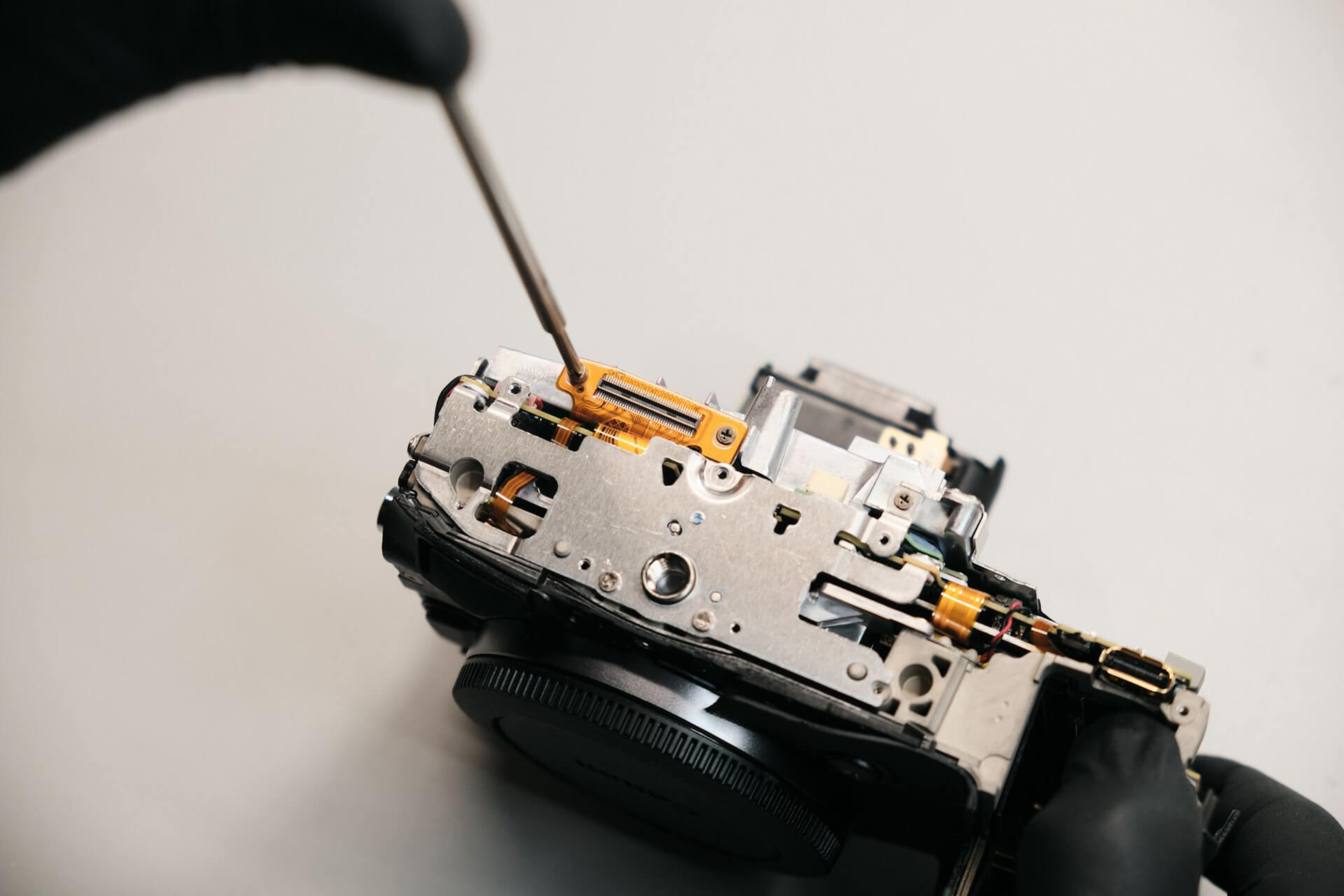
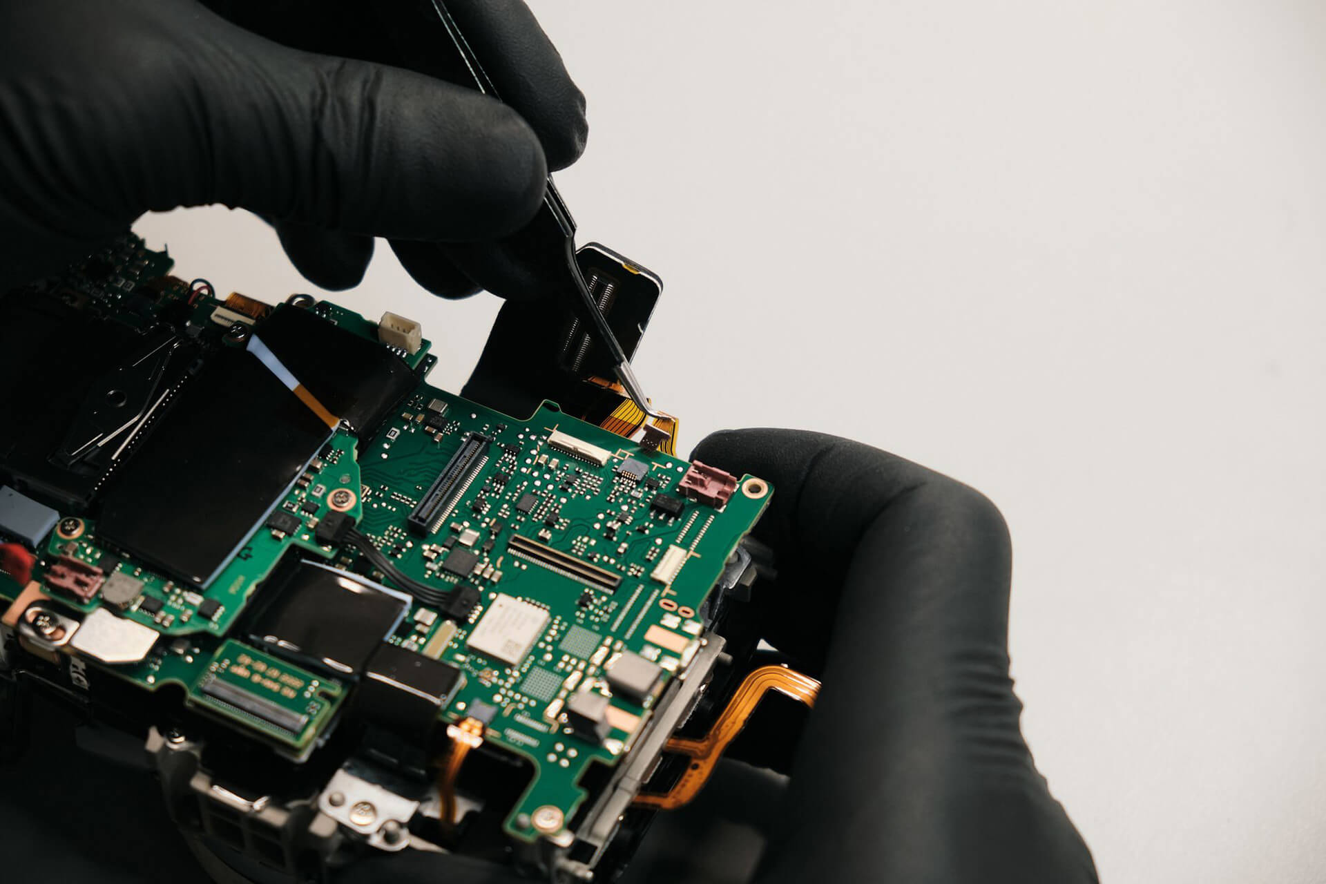
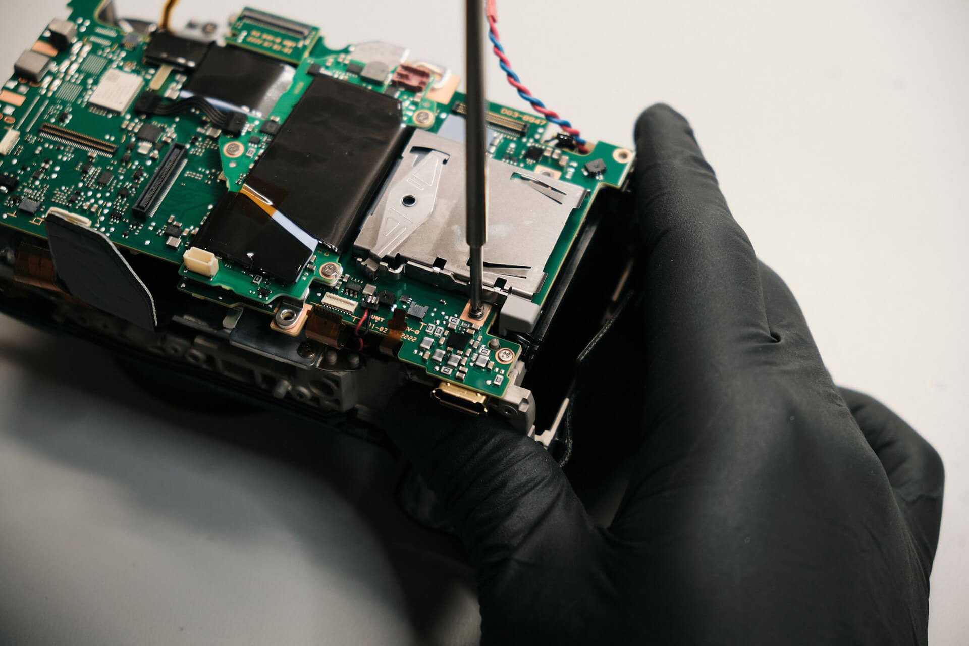
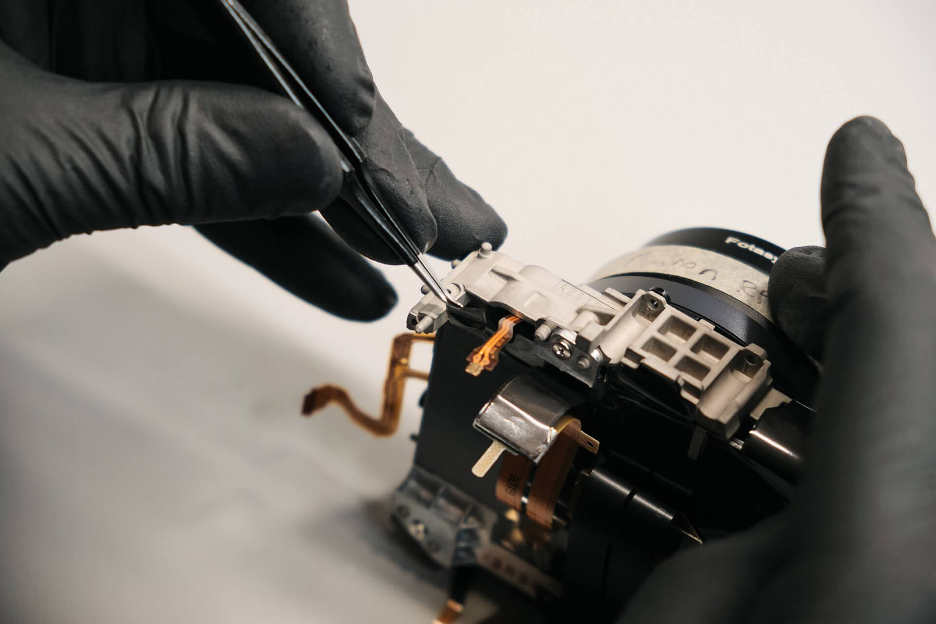
Now we needed to remove the circuit board to gain access to the camera sensor, but first, the bottom bracket needed to be removed. There were four screws altogether that held it down.
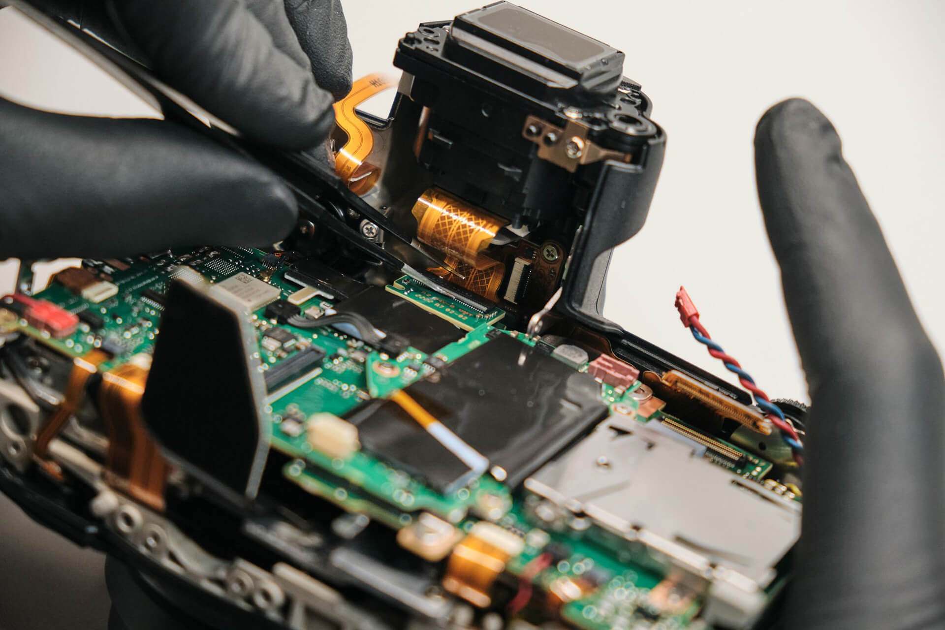
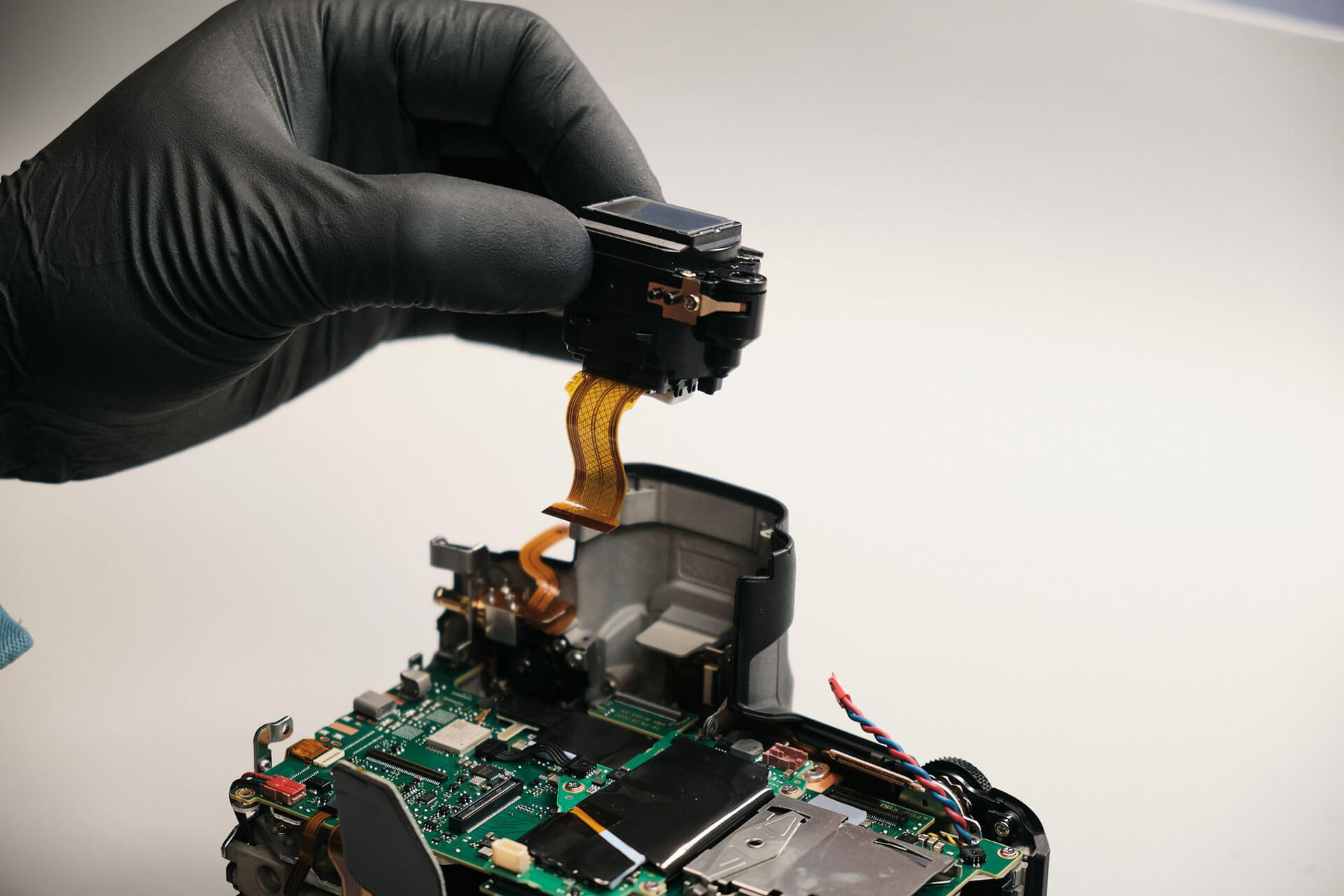
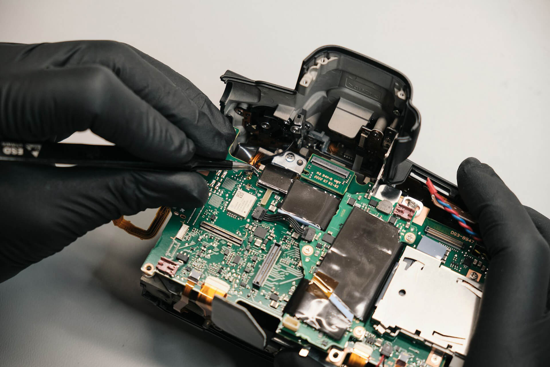
We removed the sensor ribbon and disconnected the EVF.
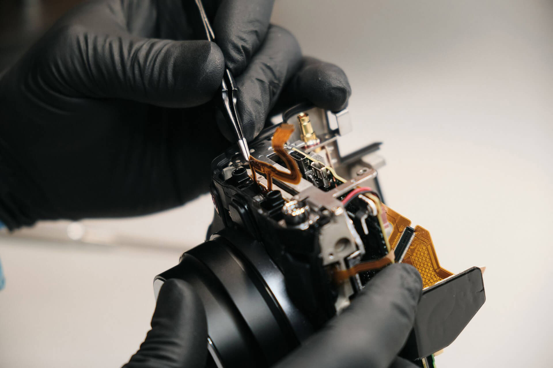
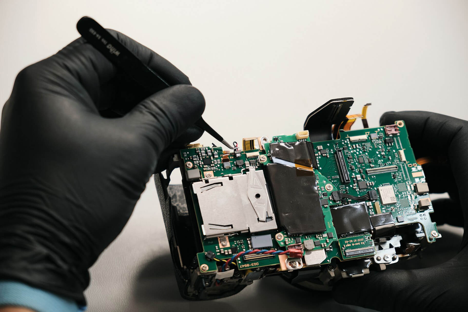
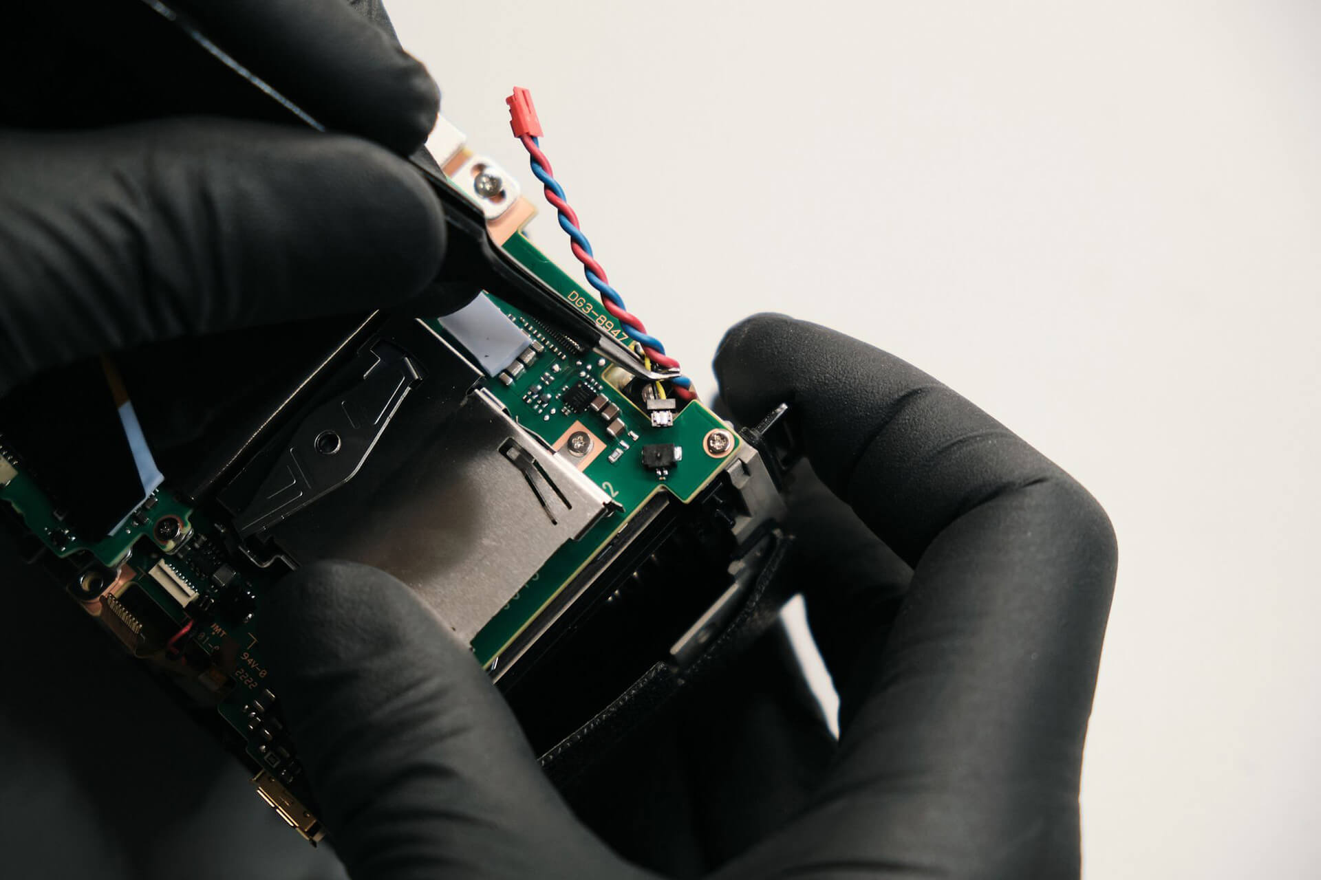
Going further, we carefully disconnected and peeled off the mic and headphone jack ribbon from the bracket. The flash sync cable needed to be disconnected from the board, and the bracket screws needed to be unfastened.
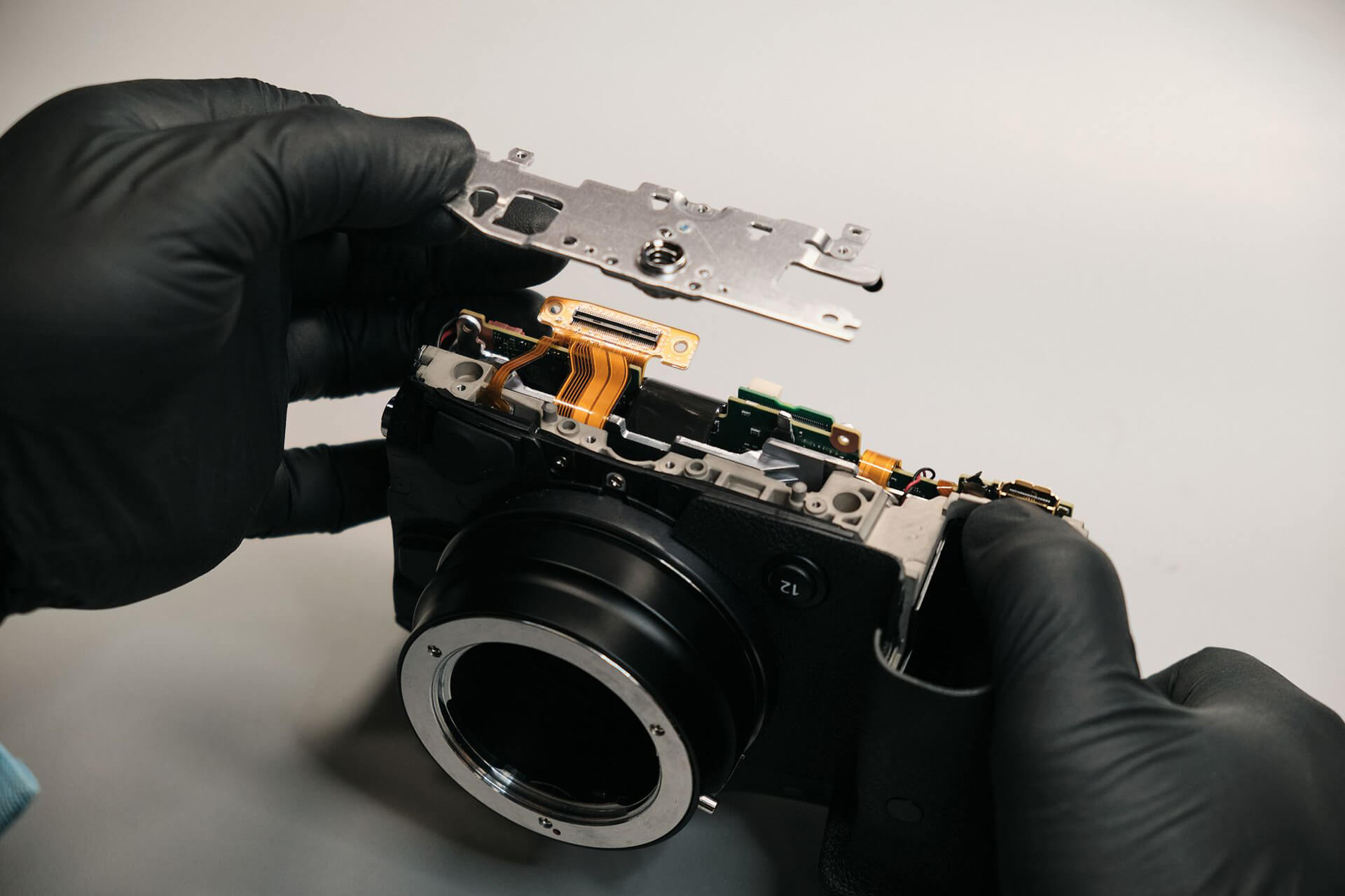
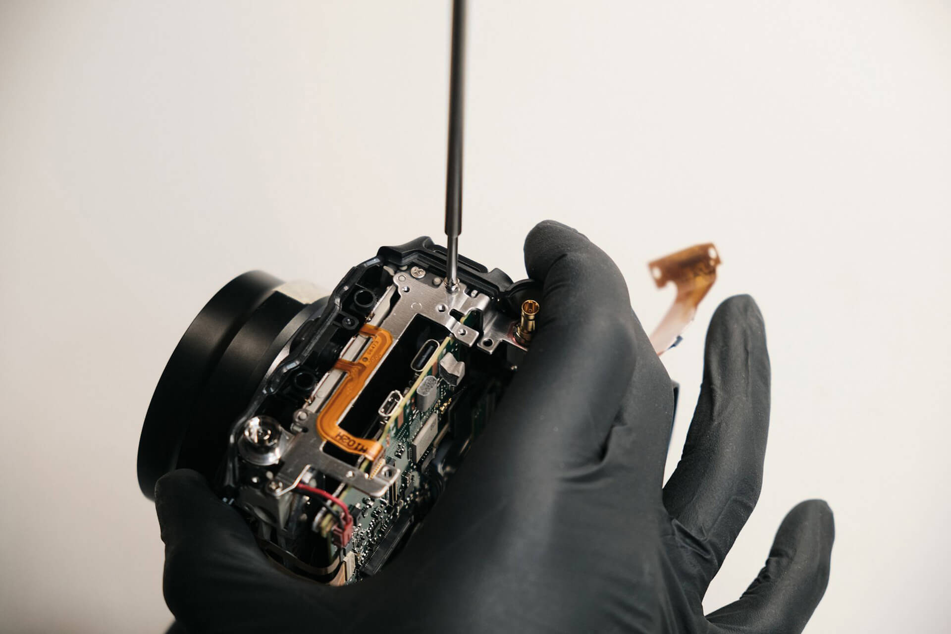
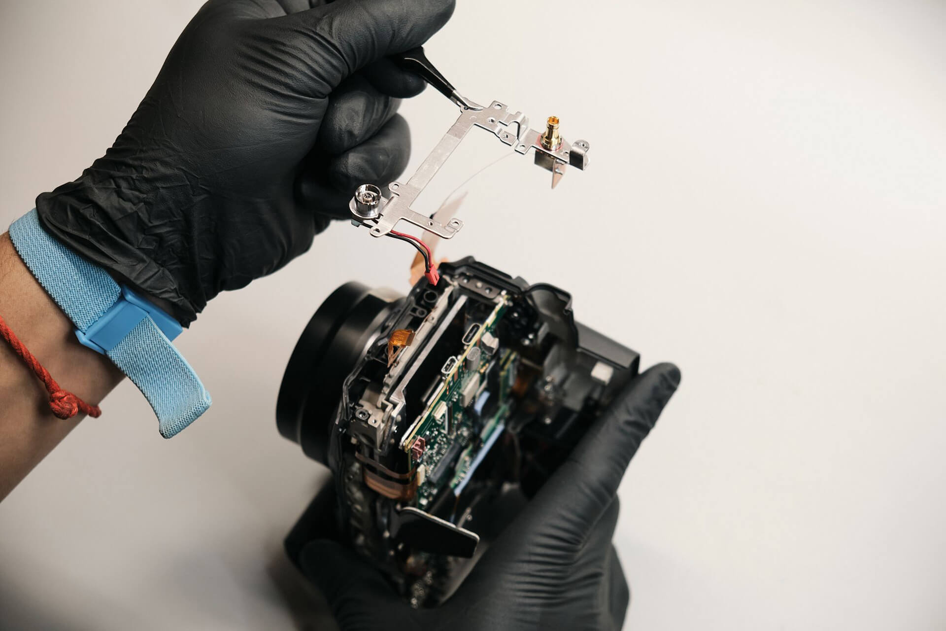
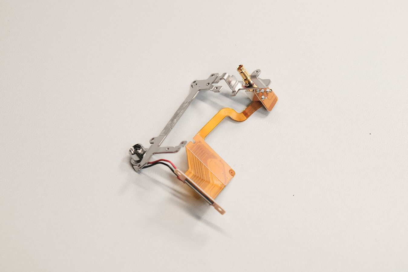
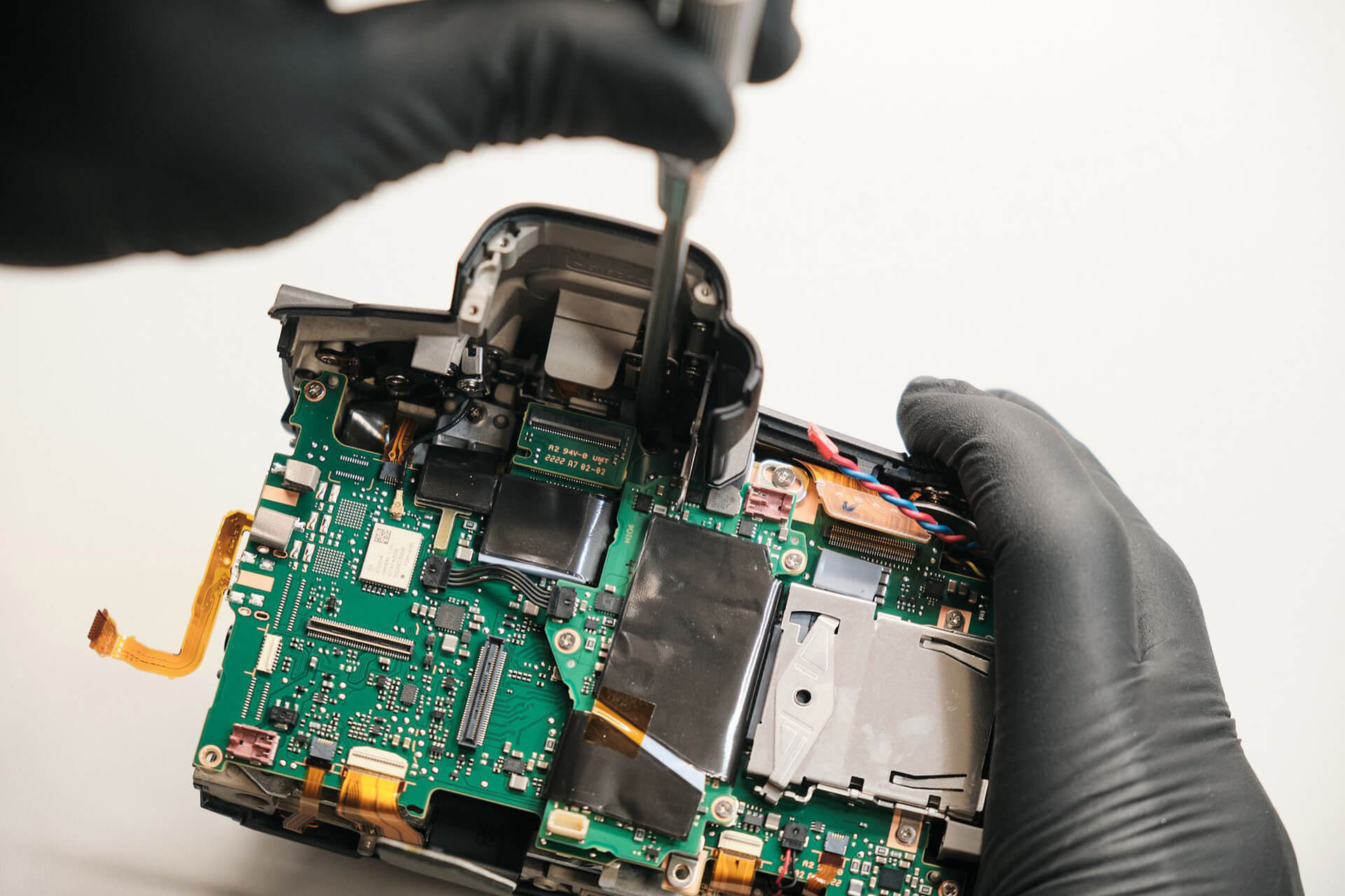
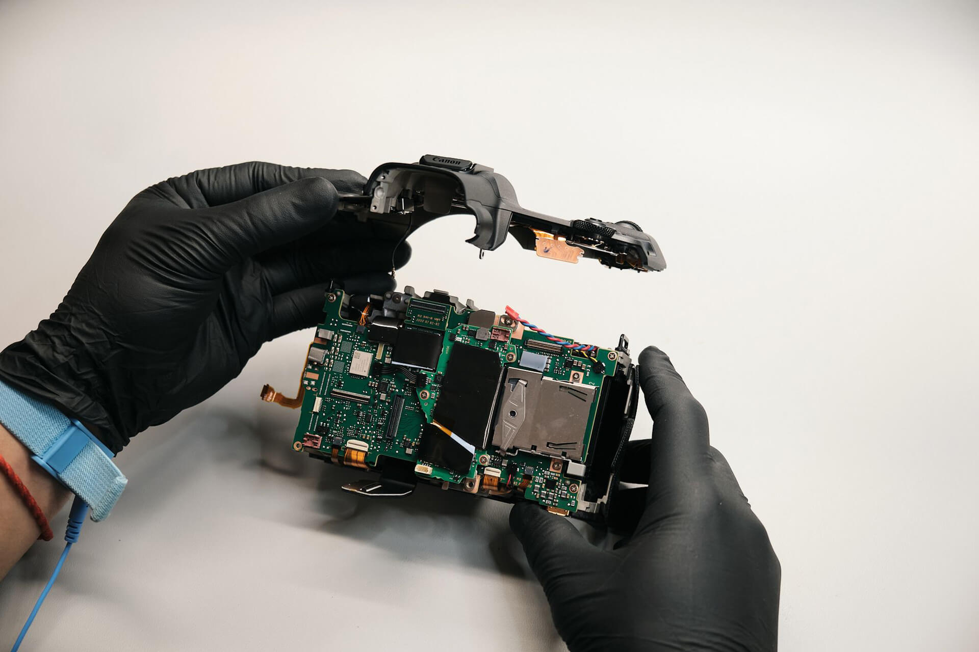
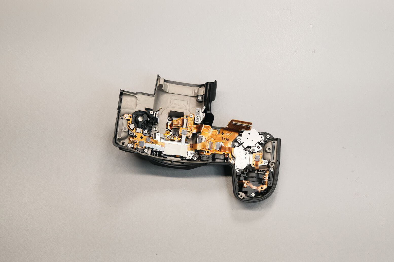
The last two screws holding the top panel were removed, and the coaxial cable was disconnected. This let us remove the entire top panel.Â
Removing the Canon R5C Circuit Board and PCB BracketÂ
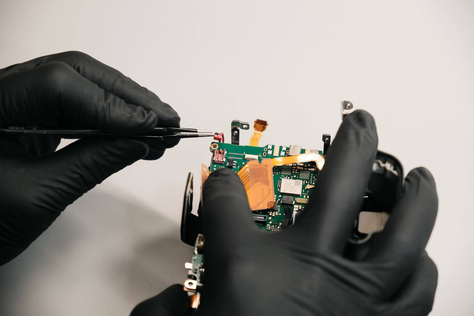
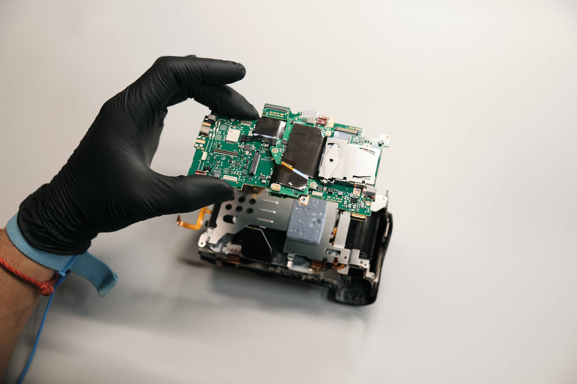
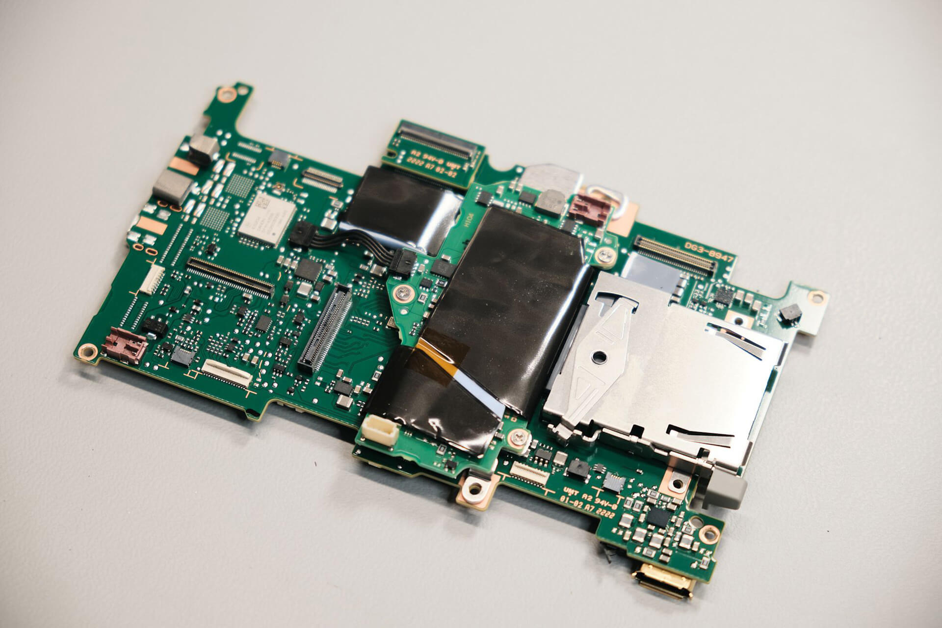
After that, we disconnected all the remaining ribbons and cables from the board.
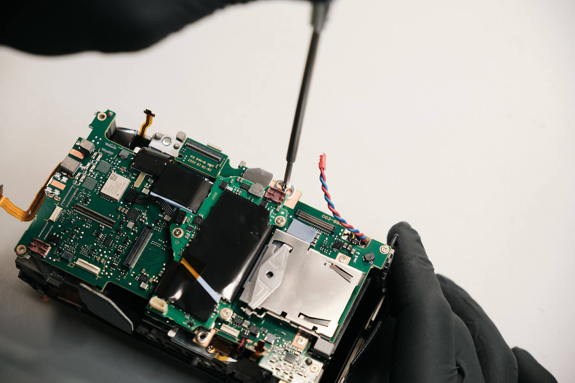
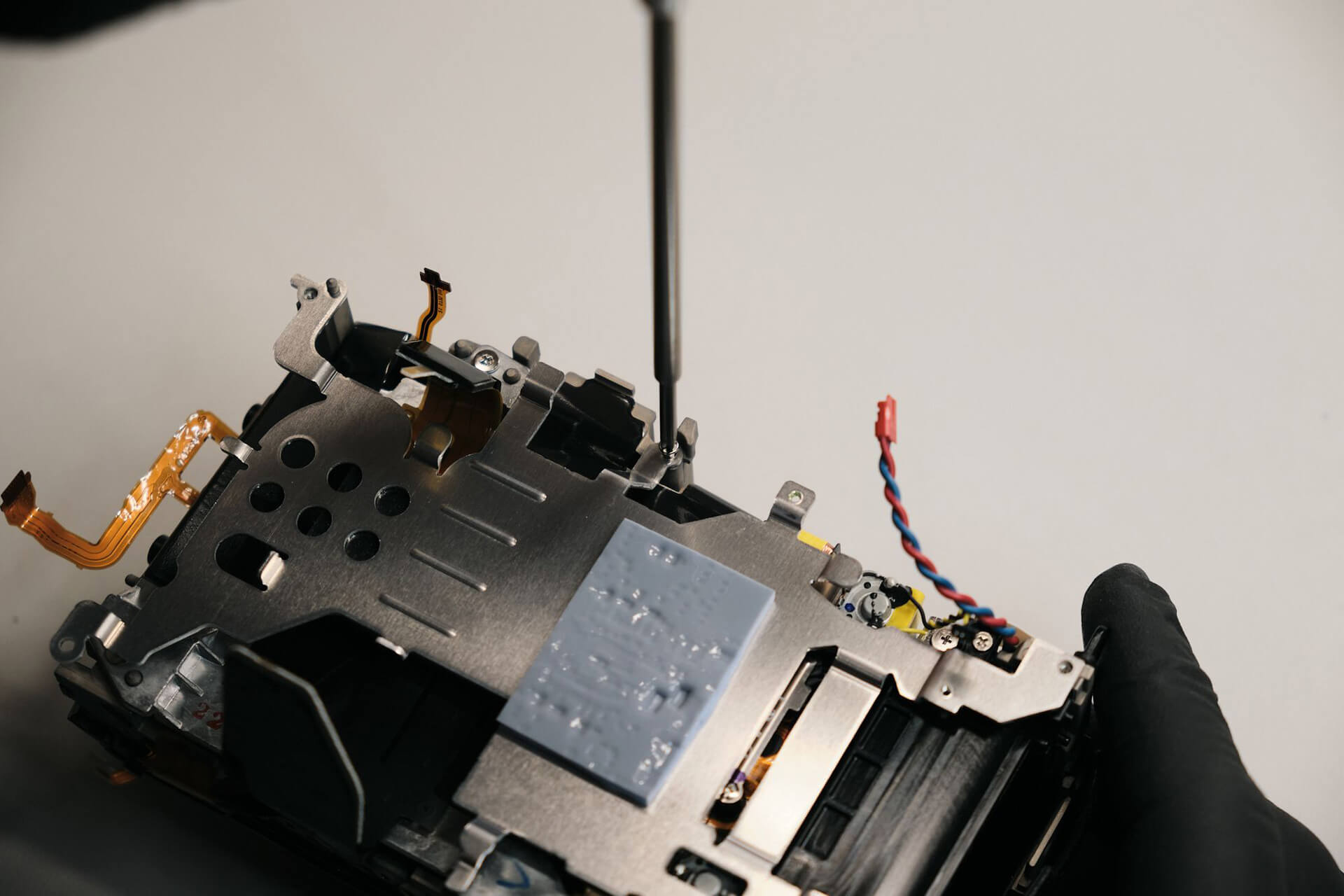
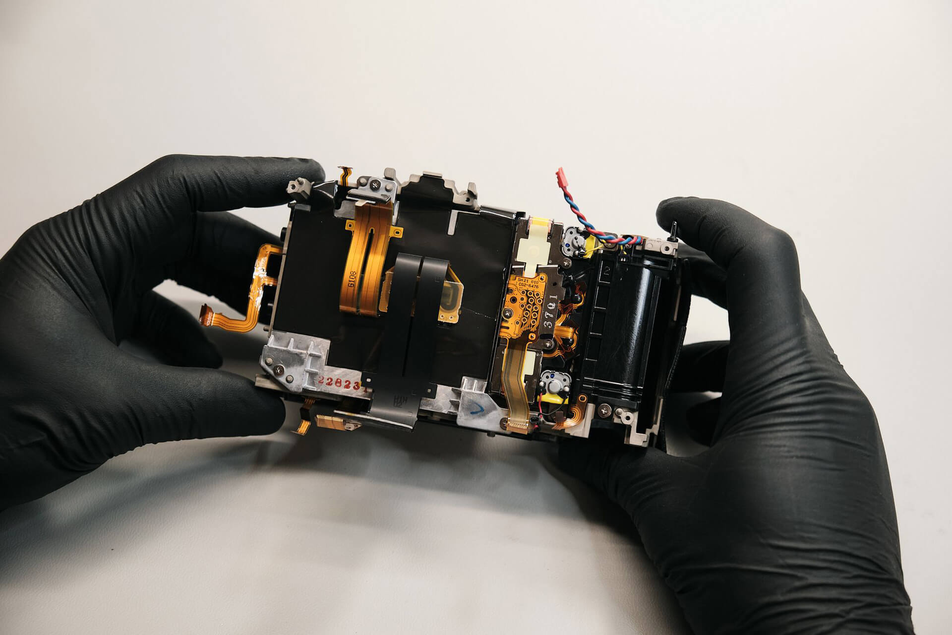
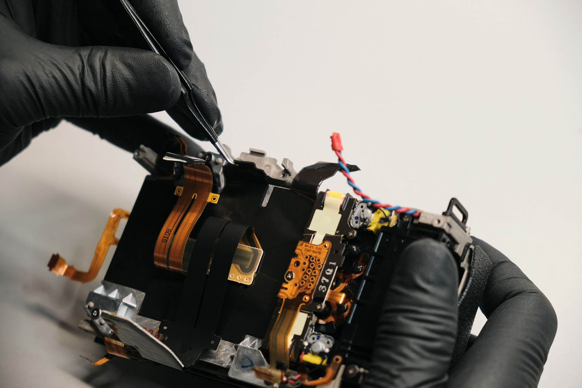
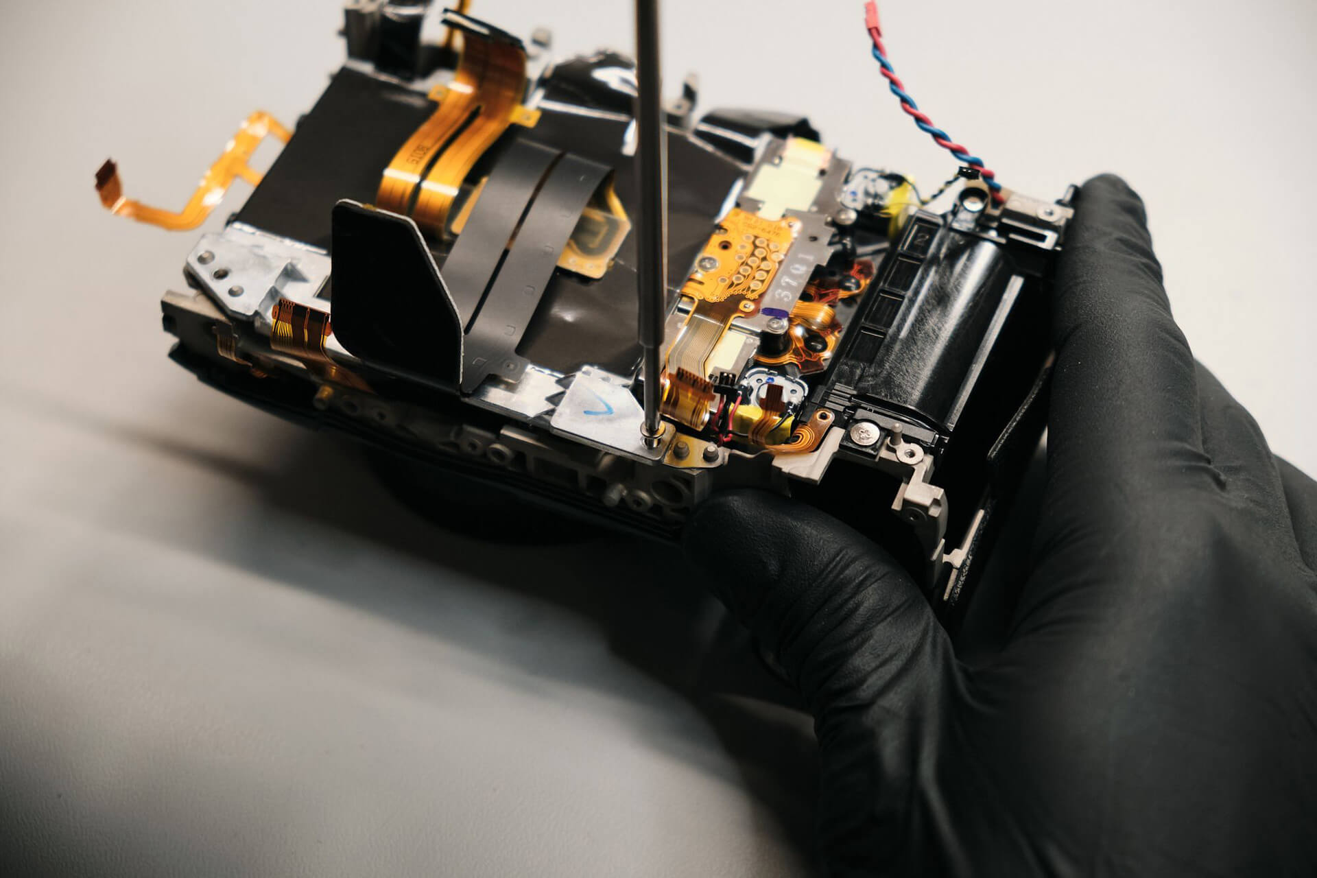
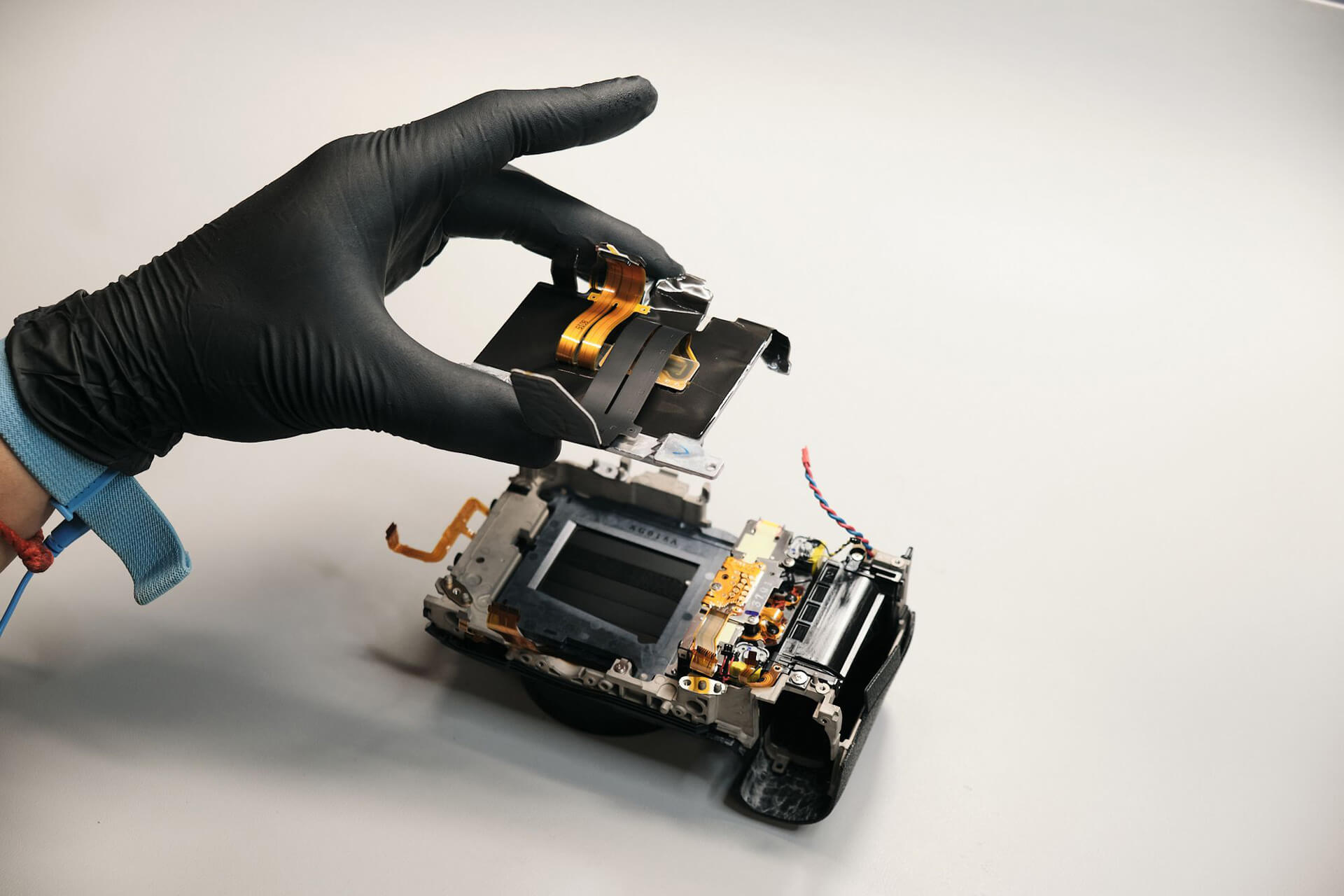
Before we could truly reach the sensor, there was one more layer to remove: the PCB bracket. This was an easy step because only two screws held it down.
Removing the Canon R5C Camera Sensor
Before we could remove the sensor, the heat transfer tape needed to be gently peeled off from the camera body.
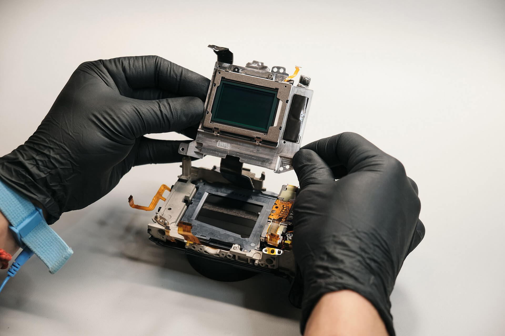
The sensor was only held down with three screws, making it easy to remove. We noticed that Canon used blue thread locker glue.
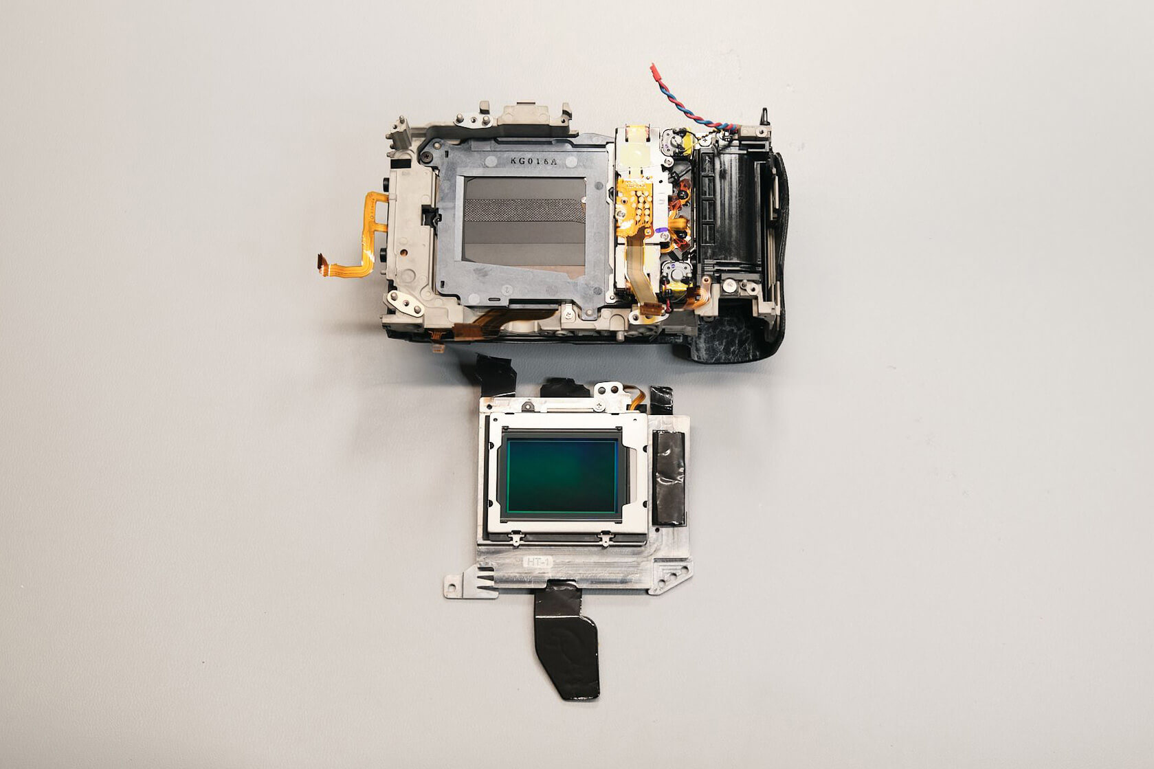
Finally, the sensor was out. The Canon R5C uses shims for focus calibration instead of a spring-loaded mechanism.
Canon R5C Teardown Difficulty and Final Thoughts
The Canon EOS R5C was easy to disassemble, as it was structurally similar to the standard Canon R5 camera, except for having more screws, according to our camera technician Jared.
Thanks for reading. We feature a new camera teardown every month. Be sure to sign up for our newsletter so you don’t miss them!
Frequently Asked Questions
How Do You Start Disassembling The Canon R5C?
The Canon R5C teardown starts by removing the screws from the bottom of the camera, including a hidden screw under the battery door. After that, the disassembly moves through the rubber grip areas, port side, eyecup, EVF area, and rear panel.
Where Are The Hidden Screws On The Canon R5C?
The Canon R5C has hidden screws under the rear panel rubber grip, the right-side leather cover grip, the port panel rubber grip, near the vent bracket, under the battery door, and near the BNC time code port. These hidden screws must be removed before the body panels can separate.
How Is The Canon R5C Rear Panel Removed?
The rear panel is removed after the exterior screws, port side screws, eyecup screws, EVF-area screws, and BNC time code port screws are taken out. Before the rear panel can fully separate, a large ribbon cable connected to the buttons and LCD monitor needs to be disconnected carefully.
How Is The Canon R5C Circuit Board Removed?
The Canon R5C circuit board is removed after the rear panel, cooling fan wire, heatsink, bottom bracket, EVF connection, top panel, and remaining board ribbons are disconnected. Six remaining screws hold the circuit board in place before it can be lifted out.
How Is The Canon R5C Camera Sensor Removed?
The Canon R5C sensor is reached after the circuit board and PCB bracket are removed. The heat transfer tape must be peeled back first, then three sensor screws can be removed. The teardown notes that the R5C uses shims for focus calibration instead of a spring-loaded mechanism.