Remove all 9 screws on the bottom of the camera and take off the plate, the silver plate underneath, and remove the battery door
2
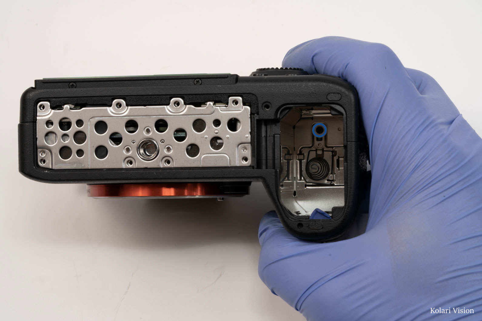
Step 2
Remove the screw in the battery compartment.
3
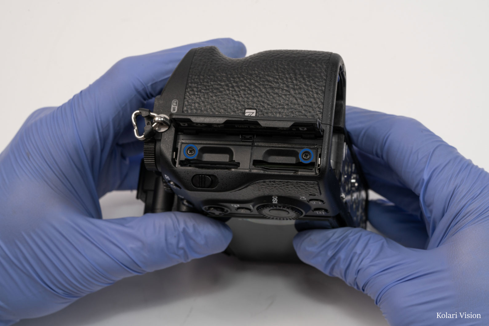
Step 3
Open the card slot door and remove the 2 screws in there.
4
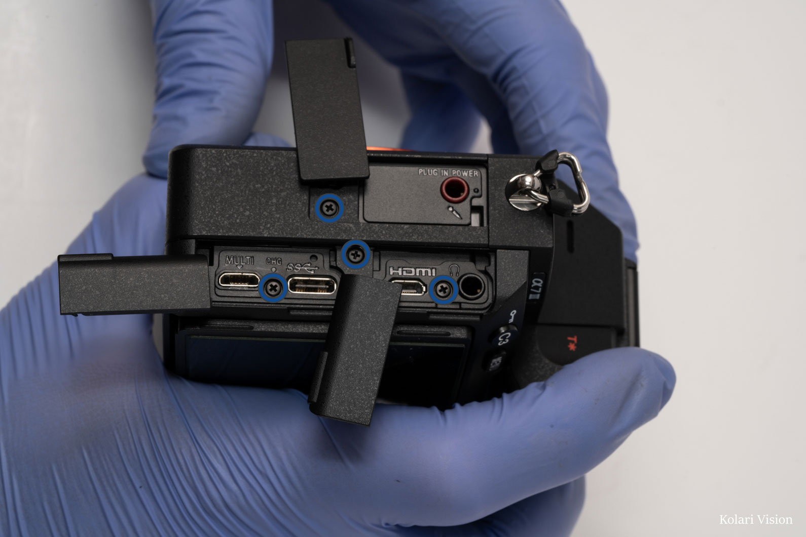
Step 4
Open the port covers and remove the 4 screws underneath
5
Step 5
Tilt-back the LCD and remove the 1 screw in the top left of the back
6
Step 6
Remove the 4 screws around the EVF and the 1 in the diopter
7
Step 7
Peel off the leathers on the handgrip, and remove the 2 silver screws towards the back.
8
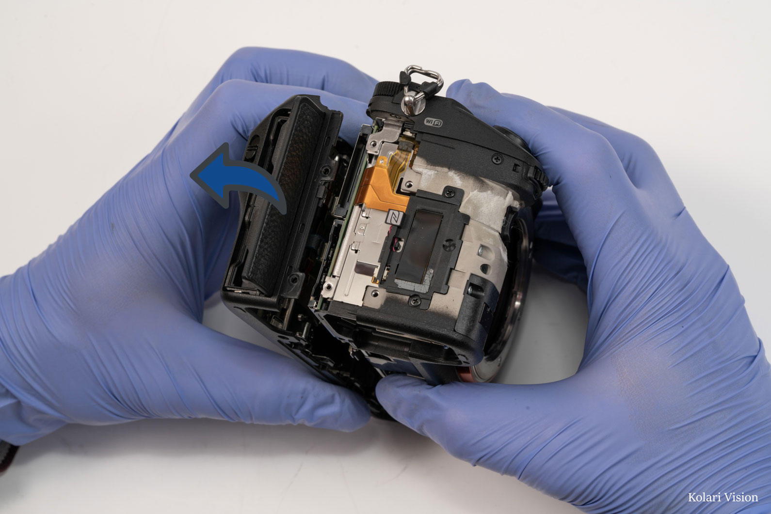
Step 8
Start pull the back panel separate from the body, but don’t completely pull it off yet.
9
Step 9
With the camera face down, lift the back panel off and disconnect the ribbon that is connecting it to the board.
10
Step 10
Disconnect the ribbon connected to the EVF, then pull the EVF out.
There is some adhesive thermal padding at the back, which is holding it back. Wiggle the EVF to loosen it, and then carefully pull on it to remove it.
11
Step 11
Next remove the top. To do so, remove the 2 screws that were behind the EVF. Then remove the screw in the top left, deep in the camera and by the “A7III” label, and the screw in the top-right, by the strap loop mount.
12
Step 12
Remove the 2 screws on the sides of the handgrip, next to the front dial.
13
Step 13
Disconnect the two ribbons connected to the top
14
Step 14
Pull off the top piece of the camera, as well as the port panel.
15
Step 15
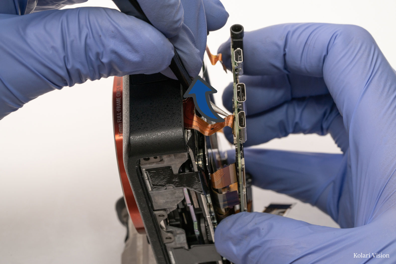
Begin removing the tape and disconnecting the ribbons. Also remove the screw holding the headphone jack.
16
Step 16
Peel the heat tape all the way back to reveal to ribbons by the card readers
17
Step 17
Remove the 5 screws holding the board
18
Step 18
There are 2 ribbon on the underside of the motherboard, located at the top on the right-side, above the card reader.
19
Step 19
There’s another ribbon on the underside of the board, in the lower left corner.
20
Step 20
Once everything is disconnected, take out the board
21
Step 21
Remove the screws holding the metal heat shielding, and take it off.
22
Step 22
Peel back the heat tape from the top and bottom. Be careful peeling it, the tape may pull apart.
23
Step 23
Peel off the tape in the lower left corner revealing a screw. Then remove the 3 senor screws.
24
Step 24
Take out the sensor.
Be careful when removing the sensor. This camera uses shims to calibrate the sensor, which are very thin metal leaves. If a shim falls out of place or is damaged, your camera will not be able to focus properly.